
Datasheet
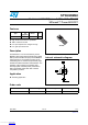


STW45NM60 Electrical characteristics
5/12
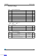
Table 6. Switching times
Symbol Parameter Test conditions Min. Typ. Max. Unit
t
d(on)
t
r
Turn-on delay time
Rise time
V
DD
= 250V, I
D
= 22.5A
R
G
=4.7Ω V
GS
= 10V
Figure 13
30
20
ns
ns
t
r(Voff)
t
f
t
c
Off-voltage rise time
Fall time
Cross-over time
V
DD
= 400V, I
D
= 45A,
R
G
=4.7Ω, V
GS
= 10V
Figure 13
16
23
40
ns
ns
ns
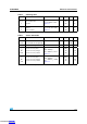
Table 7. Source drain diode
Symbol Parameter Test conditions Min. Typ. Max. Unit
I
SD
Source-drain current 45 A
I
SDM
Source-drain current (pulsed) 180 A
V
SD
(1)
1. Pulsed: Pulse duration = 300 µs, duty cycle 1.5%.
Forward on voltage I
SD
= 45A, V
GS
= 0 1.5 V
t
rr
Q
rr
I
RRM
Reverse recovery time
Reverse recovery charge
Reverse recovery current
I
SD
= 45A,
di/dt = 100A/µs,
V
DD
= 100 V, T
j
= 25°C
Figure 15
508
10
40
ns
µC
A
t
rr
Q
rr
I
RRM
Reverse recovery time
Reverse recovery charge
Reverse recovery current
I
SD
= 45A,
di/dt = 100A/µs,
V
DD
= 100 V, T
j
= 150°C
Figure 15
650
14
43
ns
µC
A
Downloaded from Arrow.com.Downloaded from Arrow.com.Downloaded from Arrow.com.Downloaded from Arrow.com.Downloaded from Arrow.com.