
Datasheet

VN5160S-E Electrical specifications
Doc ID 13493 Rev 5 9/31
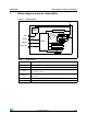
2.3 Electrical characteristics
Values specified in this section are for 8V<V
CC
<36V; -40°C<T
j
<150°C, unless otherwise
stated.
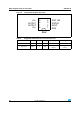
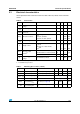
Table 6. Power section
Symbol Parameter Test conditions Min. Typ. Max. Unit
V
CC
Operating supply
voltage
4.5 13 36 V
V
USD
Undervoltage shutdown 3.5 4.5 V
V
USDhyst
Undervoltage shutdown
hysteresis
0.5 V
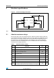
R
ON
(1)
1. Guaranteed by design/characterization
On-state resistance
I
OUT
=1A; T
j
=25°C
I
OUT
=1A; T
j
=150°C
I
OUT
=1A; V
CC
=5V; T
j
=25°C
160
320
210
m
m
m
V
clamp
Clamp voltage I
S
= 20mA 41 46 52 V
I
S
Supply current
Off-state; V
CC
=13V; V
IN
=V
OUT
=0V;
T
j
=25°C;
On-state; V
CC
=13V; V
IN
=5V;
I
OUT
=0A
2
(2)
1.9
2. PowerMOS leakage included
5
(1)(2)
3.5
µA
mA
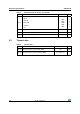
I
L(off1)
Off-state output
current
(2)
V
IN
=V
OUT
=0V; V
CC
=13V; Tj=25°C
V
IN
=V
OUT
=0V; V
CC
=13V; T
j
=125°C
0
0
0.01 3
5
µA
I
L(off2)
V
IN
= 0V; V
OUT
= 4V -75 0
V
F
Output - V
CC
diode
voltage
-I
OUT
= 0.6A; T
j
= 150°C 0.7 V
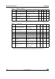
Table 7. Switching (V
CC
=13V; T
j
= 25°C)
Symbol Parameter Test conditions Min. Typ. Max. Unit
t
d(on)
Turn-on delay time R
L
= 13 (see Figure 6)10µs
t
d(off)
Turn-off delay time R
L
= 13(see Figure 6)15µs
dV
OUT
/dt
(on)
Turn-on voltage slope R
L
= 13 See Figure 21 Vµs
dV
OUT
/dt
(off)
Turn-off voltage slope R
L
= 13 See Figure 22 Vµs
W
ON
Switching energy
losses during t
won
R
L
= 13(see Figure 6)0.04mJ
W
OFF
Switching energy
losses during t
woff
R
L
= 13(see Figure 6)0.04mJ