
Datasheet
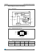


VN920SP-E Electrical specifications
Doc ID 10896 Rev 4 9/27
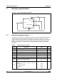
Table 7. Logic inputs
Symbol Parameter Test conditions Min. Typ. Max. Unit
V
IL
Input low level voltage 1.25 V
I
IL
Low level input current V
IN
= 1.25 V 1 µA
V
IH
Input high level voltage 3.25 V
I
IH
High level input current V
IN
= 3.25 V 10 µA
V
I(hyst)
Input hysteresis voltage 0.5 V
V
ICL
Input clamp voltage
I
IN
= 1 mA
I
IN
= - 1 mA
66.8
-0.7
8V
V
Table 8. V
CC
output diode
Symbol Parameter Test conditions Min. Typ. Max. Unit
V
F
Forward on voltage - I
OUT
= 5.3 A; T
j
= 150 °C - - 0.6 V
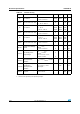
Table 9. Protections
(1)
1. To ensure long term reliability under heavy over-load or short circuit conditions, protection and related
diagnostic signals must be used together with a proper software strategy. If the device operates under
abnormal conditions this software must limit the duration and number of activation cycles.
Symbol Parameter Test conditions Min. Typ. Max. Unit
T
TSD
Shutdown temperature 150 175 200 °C
T
R
Reset temperature 135 °C
T
hyst
Thermal hysteresis 7 15 °C
I
lim
DC short circuit current
V
CC
= 13 V
5V < V
CC
< 36 V
30 45 75
75
A
A
V
demag
Turn-off output clamp
voltage
I
OUT
= 2 A;
V
IN
= 0 V;
L = 6 mH
V
CC
- 41 V
CC
- 48 V
CC
- 55 V
V
ON
Output voltage drop
limitation
I
OUT
= 1 A;
T
j
= -40 °C...150 °C
50 mV