
Full Product Manual
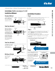


Table Of Contents
- Contents
- Overview
- Ring Terminals
- Flag Terminals
- Fork Terminals
- Pin Terminals
- Splice Connectors
- Wire Joints
- Heat-Shrinkable Terminals, Splices, Disconnects
- Disconnects and Male Tabs
- Luminaire Disconnects
- Ferrules
- Wire Termination Tools and Installation Kits
- Wire Termination Technical Information
- Shrink-Kon® Heat-Shrinkable Tubing
- Shrink-Kon® Splice Insulatorsand Insulating Covers
- Shrink-Kon® Installation Tools
- Shield-Kon® Shield Termination System
- Dragon-Tooth® Magnet WireTermination System
United States
Tel: 901.252.8000
800.816.7809
Fax: 901.252.1354
Technical Services
Tel: 888.862.3289
www.tnb.com
G-85
Shield-Kon
®
Shield Termination System
Wire Termination — Sta-Kon
®
Wire Termination & Insulation
Three installation methods are possible in the hexagonal range for a quick, neat and accurately completed termination...
at a greatly reduced production cost.
Quick and neat terminations made easy!
GSC outer sleeve
Shielding
Outer insulator
.50" (12.7 mm)
GSB inner sleeve
Shielding
Outer insulator
.50" (12.7mm)
1.0" (25.4 mm)
GSB inner sleeve Shielding
Outer insulator
GSB inner sleeve
GSC outer sleeve
GSC outer sleeve
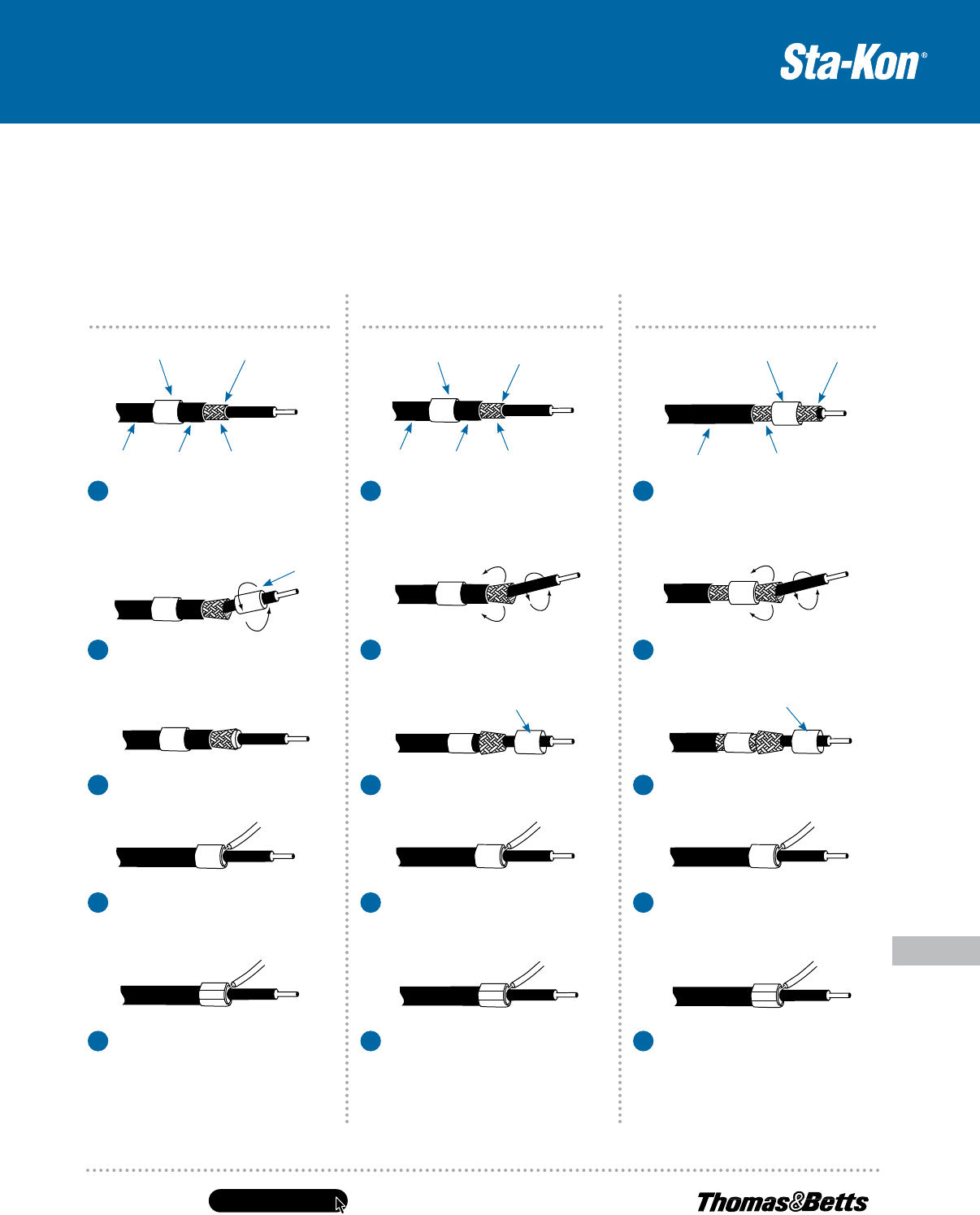
Method 1: Standard Method 2: Fold Back Method 3: Large Insulation
After stripping the shield (.50" in length),
slip the outer sleeve over the outer
insulation. If this is too big, slip the outer
sleeve on, after technique described in
Method 3.
1 1 1
After stripping the shield (.50" in
length), slip the inner sleeve over
the outer insulation.
After stripping the shield (1.0" in
length), slip the inner sleeve over
the braided shield.
Slip the ground wire (#22–#20 AWG)
under the outer sleeve (from the front
or behind) and slip the outer sleeve
over the braided shield.
Slip the drain wire (#22–#20 AWG) under
the outer sleeve (from the front
or behind) and slip the outer sleeve
over the braided shield.
Slip the ground wire (#22–#20 AWG)
under the outer sleeve (from the front
or behind) and slip the outer sleeve
over the braided shield.
Position the outer sleeve and ensure
that the ends of all wires in the braided
shield and ground wire are covered.
Crimp both sleeves with the correct
tool and die. Finished.
Position the outer sleeve and ensure
that the ends of all wires in the braided
shield and ground wire are covered.
Crimp both sleeves with the correct
tool and die. Finished.
Position the outer sleeve and ensure
that the ends of all wires in the braided
shield and ground wire are covered.
Crimp both sleeves with the correct
tool and die. Finished.
Position the inner sleeve so that about
.06" protrudes beyond the end of the
braided shield.
Fold back the braided shield over the inner
sleeve and slip the outer sleeve over the
braided shield.
Fold back the braided shield over the inner
sleeve and slip the outer sleeve over the
braided shield.
Widen the braided shield by gently rotating
the inner conductor, then slip the inner
sleeve under the braided shield.
Widen the braided shield by gently rotating
the inner conductor.
Widen the braided shield by gently rotating
the inner conductor.
2 2 2
3 3 3
4 4 4
5 5 5