
Full Product Manual
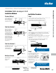


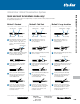


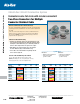
Table Of Contents
- Contents
- Overview
- Ring Terminals
- Flag Terminals
- Fork Terminals
- Pin Terminals
- Splice Connectors
- Wire Joints
- Heat-Shrinkable Terminals, Splices, Disconnects
- Disconnects and Male Tabs
- Luminaire Disconnects
- Ferrules
- Wire Termination Tools and Installation Kits
- Wire Termination Technical Information
- Shrink-Kon® Heat-Shrinkable Tubing
- Shrink-Kon® Splice Insulatorsand Insulating Covers
- Shrink-Kon® Installation Tools
- Shield-Kon® Shield Termination System
- Dragon-Tooth® Magnet WireTermination System
United States
Tel: 901.252.8000
800.816.7809
Fax: 901.252.1354
Technical Services
Tel: 888.862.3289
www.tnb.com
G-89
Shield-Kon
®
Shield Termination System
Wire Termination — Sta-Kon
®
Wire Termination & Insulation
The design advantages are:
• Positive selection of inner and outer sleeves and installing
die by a complete color-coded system
• A more reliable grounding termination because only
one ground wire connection is made — conventional
daisychain jumper method is eliminated
• Smaller, more compact bundle is easy to inspect
• Only one ground wire is required; however, additional
ground wires may be used if needed
• Smooth insulator protects conductor insulation
• With one stroke of the tool, the interlace die will produce
a 360° compression, uniformly securing all individual
shields around the connector
The Shield-Kon
®
Connector System for multiple-conductor shielded cable is
based on the principle of cold swaging. It utilizes a two-piece compression
connector color coded to match the proper die. The connector consists of
ahard brass collector inner ring with a tough, smooth insulator and a soft
copper compression outer ring. Each set of rings and matching installing
diewill connect a minimum of five shielding braids with one ground wire.
The maximum number of braids is limited only by the space between the
inner and outer rings.
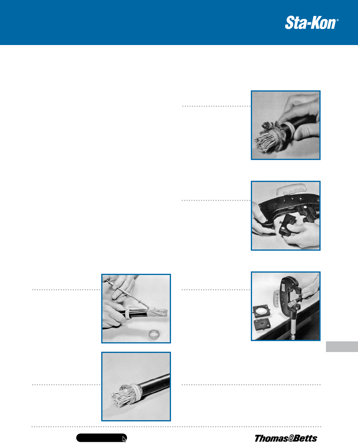
Step 1
After overall insulation is removed
to expose shielded cables, each
conductor must befreed from the
shielding braid. TheThomas &
Betts lead extractor toolsimplifies
this operation by pushing theinner
conductor through an opening
in theshielding braid. The braid
is then folded back until all
conductors are freed.
Step 2
Flattened shielding braids
areevenly distributed around
theperiphery of the inner
collectorring.
Step 3
Position outer compression
ringover the flattened shielding
braid, locating it over the center of
the inner collector ring. Braidmay
be trimmed even with the edge of
the outer compression ring before
or after compression. Ground wire
or wires may be inserted between
the outer compression ring and
the shield prior tocompression.
Step 4
Selection of compression dies
isdetermined by color coding
on rings. The dies are color
coded tomatch the rings. The
appropriate dies are easily inserted
or removed bydepressing die-
locking button shown.
Step 5
The prepared cable is placed
in the installing die and compressed.
Tool operates on hydraulic power
output, developing 9800 ±200 psi
operating pressure.
Step 6
Completed installation of the “single fold–fold forward” method typifies
the reliability, compactness and neatness that is obtained with all
Thomas & Betts recommended installation methods.
Multi-Shielded Cable Connector
Installation Procedure
Terminate multiple-conductor shielded
cable quickly and easily!