
Swimming Pool Pump User Manual


7
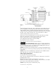
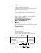
Grounding/Bonding
Install, ground, bond and wire motor according to local or National Electrical
Code requirements.
Permanently ground motor. Use green ground terminal provided under motor
canopy or access plate (See Figure 3); use size and type wire required by
code. Connect motor ground terminal to electrical service ground.
Bond motor to pool structure. Use a solid copper conductor, size No. 8 AWG
(8.4 sq.mm) or larger. Run wire from external bonding lug (see Figure 3) to
reinforcing rod or mesh.
Connect a No. 8 AWG (8.4 sq.mm) solid copper bonding wire to the pressure
wire connector provided on the motor housing and to all metal parts of the
swimming pool, spa, or hot tub and to all electrical equipment, metal piping
or conduit within 5 feet (1.5 m) of the inside walls of swimming pool, spa, or
hot tub.
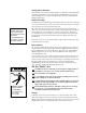
Wiring
Pump must be permanently connected to circuit. See Figures 4A, 4B, and 4C
for wiring connection diagrams. Match wire and circuit breaker sizes to cor-
rect Fusing and Wiring Data Chart (Page 8). If other lights or appliances are
also on the same circuit, be sure to add their amp loads to pump amp load. (If
unsure how to do this or if this is confusing, consult a licensed electrician.)
Use the load circuit breaker as the master on-off switch.
Install a Ground Fault Circuit Interrupter (GFCI) in circuit; it will sense a short-
circuit to ground and disconnect power before it becomes dangerous to pool
users. For size of GFCI required and test procedures for GFCI, see manufac-
turer’s instructions.
In case of power outage, check GFCI for tripping (which will prevent normal
water circulation). Reset if necessary.
NOTICE: If you do not use conduit when wiring motor, be sure to seal wire
opening on end of motor to prevent dirt, bugs, etc., from entering motor.
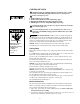
BONDING
LUG
GREEN
GROUND
SCREW
510 0993
Figure 3: Typical ground screw and
bonding lug locations.
Figure 4A: Single-phase, single speed
wiring connection diagram.
For 3-phase connection, refer
to motor nameplate.
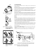
Figure 4B: Wiring connections for
plug-in type terminal board
(Single speed, single phase
motors)
Figure 4C: Single-phase, 2-speed wiring hookup diagram
(Models P4RA6YF-187L and P4RA6YG-188L).
A
B
L2
L1
White
230
Volt
Lines
Blue
469 0194A
Power Supply for
Optional Timer.
Low Spd
High Spd
Circuit
Protector
Remote
SPDT
Switch
Ground (Green)
Common
If using timer, Connect
Timer Motor to Low Speed Only
Minimum switch and timer amp rating must equal Branch Fuse
Rating given in "Recommended Fusing and Wiring Data" table.
A
B
L2
L1
230
Volt
Lines
Back of
motor
with
Terminal
Board
1168 0794
Pull plug
straight
out from
terminal
board.
1.
1.
2.
2.
Plug in again
with arrow
on plug
pointing to
'115 Volts'.
A
L1
230
Volts
115
Volts
A
L1
230
Volts
115
Volts
Ground
Screw
3962 0401 A
115 V
230 V
230 Volt to 115 Volt Conversion. Move plug to change voltage.
Ground
Screw
230V
115V
230V
115V
A
A
L2
L2
L1
L1
230V
115V
A
A
L2
L2
L1
L1
230V
115V
Power Supply
Wires
230 Volt to 115 Volt Conversion. Move plug to change voltage.