CERTIFIED ® ® SR POOL AND SPA HEATER 120/240 VAC NATURAL GAS/LP GAS O W N E R’ S M A N U A L ED SPE LOW X AU 2 P PUM STER BOO ED H SPE HIG X AU 1 ER FILT P PUM INSTALLATION, OPERATION & PARTS MODELS 200K BTU/HR 333K BTU/HR 400K BTU/HR SR200NA, SR200LP SR333NA, SR333LP SR400NA, SR400LP, SR400HD SPECIAL INSTRUCTIONS TO OWNER Retain this manual for future reference. This manual supplies information for the installation, operation, and servicing of the appliance.
Table of Contents INSTALLATION, OPERATION AND SERVICE MANUAL Safety . . . . . . . . . . . . . . . . . . . . . . . . . . . . . . . . . . . . . 2 General Specifications, Requirements . . . . . . . . . . . . . . 3 Description of the Heater . . . . . . . . . . . . . . . . . . . . . . . 4 Sequence of Operation . . . . . . . . . . . . . . . . . . . . . . . . . 4 Owner’s Operating Instructions . . . . . . . . . . . . . . . . . . 4 Before Startup. . . . . . . . . . . . . . . . . . . . . . . . . . . .
The heater is supplied with an integral venting system for outdoor installation. A vent conversion kit (See Page 14 for Part Numbers for Conversion Kits) is available for installations in enclosures (Canada) or indoors (U.S.). Use the specified venting, and only the specified venting, when heater is installed in an enclosure or indoors. In Canada, this pool heater can only be installed outdoors or in an enclosure that is not normally occupied and does not directly communicate with occupied areas.
The heater may not be installed within five feet of the inside surface of a pool or spa unless it is separated by a solid fence, wall or other permanent barrier. Propane (LPG) fired heaters must not be installed in Massachusetts, by order of the Massachusetts State Fire Marshall. For more information, call the Fire Marshall’s office. SEQUENCE OF OPERATION An electronic temperature sensing thermistor in the manifold adapter inlet controls the heater operation.
3. Pregnant women beware! Soaking in water above 102°F (39°C) can cause fetal damage during the first three months of pregnancy (resulting in the birth of a brain-damaged or deformed child). Pregnant women should follow the 100°F (38°C) maximum rule. 4. Before entering the spa or hot tub, users should check the water temperature with an accurate thermometer; spa or hot tub thermostats may err in regulating water temperature. 5.
10. Set 3-way valves on inlet and outlet to pool or spa, as appropriate. 11. Turn on all electric power to the appliance. 12. Press either the POOL ON or SPA ON button switches on the operating control. 13. Set the thermostat to desired setting (NOTICE: Set point must be above actual water temperature or burner will not fire). See OPERATING CONTROL below. 14. The blower should come on immediately, and after about 20 seconds, the burner should fire.
The five operating switches are: After start-up, the outlet water pipe should feel slightly warmer than the inlet pipe. If it feels hot, or if you hear the water in the heater boiling, there may not be enough water flow to the appliance. Make sure that the filter is not plugged. If water temperature remains high but the unit continues to operate, turn off the appliance and call your service technician. POOL ON Press this button to govern heater operation by the pool temperature setting.
CARE AND MAINTENANCE Explosion hazard. Purging the system with compressed air can cause components to explode, with risk of severe injury or death to anyone nearby. Use only a low pressure (below 5 PSI or 35 kPa), high volume blower when air purging the heater, pump, filter, or piping. 4. Remove the Water Pressure Switch. Plug the port in the manifold to prevent bugs and dirt from getting into the manifold. 5. Drain the plastic inlet/outlet manifold through the outlet pipe.
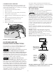
HEATER CLEARANCES – OUTDOOR INSTALLATION INSTRUCTIONS The heater must be installed with the top of the vent at least 10 feet (3M) below, or to either side of, any opening into a building. If the heater is located under a roof or deck overhang, there must be at least three feet (1M) clear space between the bottom of the overhang and the top of the heater exhaust vent. The heater must be at least six inches (15cm) from the nearest wall (clearance for service access will depend on the installation).
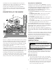
The heater is design certified by CSA International for installation on combustible flooring; in alcoves; basements; in closet or utility rooms (in the U.S.) CONTROL PANEL INDEXING The exhaust discharges vertically from outside the vent cover. The heater control panel assembly on top of the jacket can be turned to any of six positions for convenient access to the panel as follows: 1. Unbolt and separate the jacket halves. 2. Pull hair pin clips. 3. Depress plastic clips on the control panel assembly.
CSA B149.1, Natural Gas and Propane Installation Codes, as applicable, and any local codes that may apply. The minimum net free area in square inches shall be as follows: HEATER CLEARANCES – OUTDOOR SHELTER (Canada) or INDOOR (U.S.) The following clearances must be maintained from combustible surfaces: TOP ...........................6 INCHES (15cm) ALL SIDES ..................6 INCHES (15cm) VENT .........................
Flue Collar to the Vent Body. Before connecting the metal Flue Collar to the Vent Body, wet a clean cloth or paper towel with isopropyl alcohol (rubbing alcohol) and vigorously wipe the socket of the Vent Body. Immediately wipe the cleaned surfaces dry with a clean cloth or paper towel. Repeat for the exterior of the 4” end of the metal Flue Collar. Attach the metal Flue Collar to the Vent Body using the RTV supplied with the kit, following the vent manufacturer’s instructions (included with kit).
5. Use Listed firestops for floor and ceiling penetrations. Use Listed thimble for wall penetrations. Use a Listed roof flashing, roof jack, or roof thimble for all roof penetrations. Do not fill the space around the vent (that is, the clear air space in the thimble or firestop) with insulation. The roof opening must be located so that the vent is vertical. 6. Do not run the heater vent into a common vent with any other appliance. 7.
from the heater at least 1/4” per foot (2cm/M). Install Listed condensate drains at low points where condensate might collect. Plumb condensate drains to a drain through hard piping or high-temperature tubing such as silicone rubber or EPDM rubber – do not use vinyl or other low temperature tubing. Follow drain manufacturer’s installation instructions. 5. Use Listed firestops for floor and ceiling penetrations. Use Listed thimble for wall penetrations.
8. 4' Min. Vent Termination Vent Termination 4' Min. 4' Min. 1' Minimum above snow or finished grade (whichever is higher) Max 12" Min 3" 4' Min. Vent Termination 1' Min. Table 6: Maximum Vent Length At least 7' above grade adjacent to public walkways Gas Meter Forced Air Inlet 4” Special Gas Vent (Vertical or Horizontal)* No. of 90° Elbows Maximum Length in Feet (M) 0 25 Ft. (7.6M) 1 20 Ft. (6.1M) 2 15 Ft. (4.6M) 3 10 Ft. (3.
A manual bypass valve should be installed across the heater when the pump flow exceeds 120 GPM (454 LPM). See instructions below for setting of the manual bypass. Make sure that the outlet plumbing from the heater contains no shut-off valves or other flow restrictions that could prevent flow through the heater (except as noted below). To switch flow between the pool and spa, use a diverter valve. Do not use any valve that can shut off the flow.
Do NOT sanitize the pool by putting chlorine tablets or sticks into the skimmer(s). When the pump is off, this will cause a high concentration of chlorine to enter the heater, which could cause corrosion damage to the heat exchanger.
Pressure Switch is no longer adequate. A Flow Switch must be installed instead. NOTICE: Heater operation with incorrect Pressure Switch setting may cause operation with no water flow. Operation of the heater without sufficient water flow may severely damage it. Verify proper operation of the water pressure switch at the start of every season and every six months thereafter by the following steps: 1. Lower the thermostat setting to turn off the heater. 2.
To avoid water damage or scalding from operation of the relief valve, install a drain pipe in the outlet of the pressure relief valve that will direct water discharging from the valve to a safe place for disposal. Do not install any reducing couplings or valves in the drain pipe. The drain pipe must be installed so as to allow complete drainage from the valve and drain line. The relief valve should be tested at least once a year by lifting the valve lever.
GAS CONNECTIONS PRESSURE TESTING The heater requires a gas supply of not less than 4” (10.2cm) wc and not more than 14” (35.6cm) wc. Gas supply pressures outside of this range may result in improper burner operation. A minimum inlet pressure of 4” (10.2cm) wc is required to maintain input rating. The gas supply must be installed in accordance with the National Fuel Gas Code, ANSI Z223.1, or standard CSA B149.1, Natural Gas and Propane Installation Codes, as applicable and all applicable local codes.
Connect the L1 of the power supply to the black wire, the L2 or neutral lead to the red wire, and the ground wire to the green wire (See Figure 23). A time clock controlling the filter pump should have a lowvoltage Fireman’s Switch that switches off the heater at least 15 minutes before shutting off the pump. NOTICE: When using a timer and Fireman’s Switch, the heater’s power supply should come from the load side of the timer. The Fireman’s Switch completes the circuit for the low voltage safety switches.
6. Reinstall and bolt up the jacket halves. The fuse for the Fireman’s Switch is a 1.25 amp 1-1/4x1/4” fast blow fuse, available locally. MAXIMUM TEMPERATURE SET POINT 1. Unbolt and remove upper jacket halves (see Figure 3, Page 5). 2. Depress clips and remove control panel board dome (see Figure 9, Page 10). 3. Push the Max. Temp. Set Point button on the back of the control board (see Figure 26).
Initial Troubleshooting Only qualified, trained service technicians with appropriate test equipment should service the heater. Remember that all parts of the system affect heater operation. Before starting this troubleshooting procedure, make sure that the pump is running correctly, that there are no blockages in the system, that the valves are correctly set and that the time clock is correctly set and is running. IMPORTANT! READ ME FIRST!! on either 120 Volts AC or 240 Volts AC. 2.
Heater Will Not Fire - A Start NO Is green “SPA” or “POOL” LED “on” YES Check that correct 12-pin plug is installed (red is 240V, black is 120V) YES Depress “POOL” or “SPA” ON button on Membrane Pad. Does “POOL” or “SPA” LED come on? NO YES Check for line voltage to heater. NO Heater should fire on demand for heat. Restore power to heater. YES NO If plug is not installed: Install correct plug. 240V plug in 120V circuit: Replace with correct plug.
Heater Will Not Fire - B Start Is red “SERVICE HEATER” LED “on” NO Is red “SERVICE SYSTEM” LED on? NO YES YES Verify that pump is on, filter is not blocked, and the water flow is above the minimum requirement. NO YES With pump running, adjust Water Pressure Switch to lower pressure until ‘SERVICE SYSTEM” LED goes out. Then verify that “SERVICE SYSTEM” LED goes on with pump off. Increase POOL/SPA temperature setting on Membrane Pad above actual water temperature.
Heater Will Not Fire - C Start NO Is “SERVICE HEATER” LED “on”? YES If any red diagnostic LED’s (AGS, AFS, SFS, HLS, PS, or THERMISTOR) come “on”, go to to Pages 28 and 29. NO Go to “INITIAL TROUBLESHOOTING” Turn off power to heater for 5 seconds, and turn back on. Make sure temperature setting is above water temperature. Wait one minute. YES Does heater fire and stay on? CONTINUE NO NO Did burner fire at all? Did Blower come on? YES YES Verify that gas is flowing to burner during ignition try.
Heater Will Not Fire - D IMPORTANT! READ ME FIRST!! IMPORTANT! READ ME FIRST!! If your heater is correctly connected to 240 Volts AC, The Ignition Control Module (ICM) will convert the 240VAC to an intermittent pulse to the ignitor. Digital meters don’t read this type of signal well. (An analog meter will give a better reading than a digital meter). If the ICM is bad, your volt- meter will read either 0 VAC or 240 VAC. If your ICM is good, your meter will read some voltage between 0 and 240 VAC.
Diagnostic LED’s: AGS, AFS, HLS, PS, THERMISTOR Verify that water flow rate is above minimum required for heater. AGS or HLS “on” Replace High Limit Switch (HLS) or Automatic Gas Shutoff (AGS) NO YES YES Verify that inlet water temperature is below 104° F. Service pump and filter to restore proper flow. After servicing, verify proper operation of Pressure Switch (PS). NO Replace thermistor or Control Board to correct overheating.
Diagnostic LED’s: SFS Replace Heater Membrane Pad Assembly, reset power to Heater and retry. Heater should fire. SFS “on” A) Is the Stack Flue Switch or Sensor correctly connected to the wiring harness? B) Is the Membrane Pad connected to the correct pins on the Control Board? (See Page 36) NO Replace Heater Control Board with new style board, reset power to Heater and retry. Heater should fire. NO Reconnect correctly.
Burner Troubleshooting SYMPTOM CAUSE REMEDY Loud, high-pitched whine Flame is too rich. Verify pressure tap between gas valve and blower inlet. Turn to Page 19 and verify that the gas regulator setting is 0.2” (0.5cm) wc below the blower inlet pressure. Replace gas orifice with smaller size. Flame is “fluttery.” Exhaust may have acrid smell or burner may fail to stay lit. Flame is too lean. Turn to Page 19 and verify that the gas regulator setting is 0.2” (0.5cm) wc below the blower inlet pressure.
1 For For complete complete Electrical Electrical System System parts breakdown parts breakdown (Key 1 through through 4), 4), (Key Nos. Nos. 1 See 35 See Page Page 34 2 3 OF F N O 5 6 T VEN SS PRE TAB OT PIL 9 For compete For complete Burner System Burner System parts breakdown parts breakdown (Key Nos. 5 through 9), (Key Nos. 5 through 9), See Pages 32 and 33 See Pages 31 and 32 7 4 12 8 11 4 10 For complete For complete Water System Waterbreakdown System parts parts breakdown (Key Nos.
1 2 VEN For Heater mounting bolts and clamps, purchase separately Bolt Down Bracket Kit, Part No. 42001-0085S.
REPAIR PARTS – BURNER SYSTEM Model Key No. Part Description 1 2 • 3 4 • 3 4 • Combination Gas Control Valve Kit 3/4” Union Gas Orifice Kit – NG (Incl. Key Nos. 3 and 4)† Gas Orifice – NG* Gas Orifice O-Ring Gas Orifice Kit – Propane (Incl. Key Nos. 3 and 4)† Gas Orifice – Propane* Gas Orifice O-Ring NG to Propane Conversion Kit (Incl. Key Nos. 3 and 4)† Gas Orifice – Propane* Gas Orifice O-Ring Conversion Instructions, NG to Propane* NG to Propane Conversion Decal* Propane to NG Conversion Kit (Incl.
1 2 3 4 5 6 7 8 9 10 11 12 13 15 14 16 17 18 20 19 2691 1196 REPAIR PARTS – WATER SYSTEM Model Key No. 1 1 2 3 4 • 5 6 7 8 9 9 10 11 12 13 14 15 16 17 • 18 19 20 * • ** Part Description Tube Sheet Coil Assembly Kit (Includes Key No. 2) SR400HD Tube Sheet Coil Assembly Kit (Includes Key No. 2) Coil/Tubesheet Sealing O-Ring Kit Manifold Bottom Plate Manifold O-Ring* O-Ring Kit (Incl. Key Nos.
1 2 19 3 4 18 20 17 5 16 13 14 15 6 7 11 10 12 6 9 8 REPAIR PARTS – ELECTRICAL SYSTEM Model Key No. • 1 • 2 3 • 4 5 6 7 8 9 10 11 12 13 14 15 16 • • • • 17 • • 18 19 20 * ** Part Description Display Cover Retainer Cap Kit (Incl. Key No. 1)* Display Cover Retainer Cap CPSC Warning Label Heater Display Cover Igniter Bracket Igniter/Igniter Gasket Kit (Incl. Key Nos.
Pool Heater Wiring Connection Diagram CONNECTION DIAGRAM J6 If cable from Membrane Pad is a 6-Conductor Cable, connect it to pins 4 - 9 on Operating Control Board as shown.
Pool Heater Electrical Schematic Ladder Diagram LADDER DIAGRAM 120/240 VAC L1 L2 NOTES: 1.) IGNITER L1 S1 S2 L1 L2 F1 F2 S1 24 VAC L2 S2 GND IND VAL AND TH ARE CONNECTED ON THE IGNITION MODULE. F2 F1 BLOWER GND 120/240 VAC CLASS II TRANSFORMER 24 VAC OPERATING CONTROL 24 VAC 24 VAC GND AIR FLOW SWITCH LOGIC 24V TH WATER PRESSURE SWITCH HI LIMIT SWITCH IND COM NO AGS SWITCH VAL GAS VALVE STACK FLUE SENSOR THERMISTOR SENSOR NOTES: 1.
STA-RITE LIMITED WARRANTY Pumps, filters, skimmers, underwater lights (excluding bulbs), accessories and fittings manufactured by Sta-Rite are warranted to be free of defects in material and/or workmanship for one (1) year from the original date of installation. The foregoing warranties relate to the original consumer purchaser (“Purchaser”) only. Sta-Rite Industries shall have the option to repair or replace the defective product, at its sole discretion.