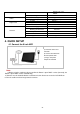
hier klicken für deutsche Version digital radio technology 2.4 GHz smart i_control Video Monitoring System Art. No. 51092 User Manual n ee r c hs cm c u 9 To 22, Android Figure shows monitor in quad setting which is only possible when using additional cameras iOS Important Prior to using the device for the first time, carefully and completely read through all operating instructions. Keep these operating instructions in a safe place; it contains important hints for operating the device.
Product description/ Intended use The weatherproof color camera of the stabo smart i_control wirelessly transmits video and audio signals of the monitored area to the monitor. Its digital technology is used to assure a transmission which is almost free from interferences and secure against eavesdropping thus protecting your privacy. You can either keep the monitored area in permanent view via the monitor or have the camera images displayed only, the Video Motion Detection function detects movements.
1. PRODUCTS OVERVIEW............................................................................................................................................ 3 1.1 9 inch Touch Screen NVR......................................................................................................... 3 1.2 Bracket ( Optional ) .................................................................................................................... 3 1.3 Camera ...........................................................
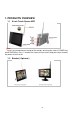
1. PRODUCTS OVERVIEW 1.1 9 inch Touch Screen NVR Note: There is only one button on the top of the monitor, which can be used as POWER key and SCREEN key. Press 1 second, the screen will turn on/off. Keep pressing 3 seconds, the power will turn on/off. 1.
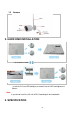
1.3 Camera 2. HARD DISK INSTALLATION * Unscrew the screw Install the 2.5 inch HDD,obliquely inserted it into the NVR and tighten the Screws. Note: If you do not install the 2.5 inch HDD, Recording will be unworkable 3.
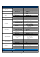
2.4G Wireless NVR Items LCD Panel System Video Audio Parameters Screen type Display Area Resolution Main processor Operating system Video compression Video input mode(IP) Video Outputs Display Resolution Audio compression Intercom Recording Modes Recording Resolution Recording Recording Frame Rate Loop Recording Hard Drive Network Apps Connections External Interface External Controller Values 9〞TFT-LCD 196.61×114.15mm 1024(H)×RGB×600(V) ARM9EJ-S RTOS H.264 4*720P HDMI(HD-720P) Max.
Video Night Vision Focal Length Video Quality Viewing Angle IR LED Night Vision Distance IR Cut Filter Power Supply Working Environment General waterproof Dimension Weight progressive scan CMOS 3.6mm 720p 70°(Diagonal) 850nm 20-30 meters Yes DC 5V/2A -10~+60℃ /Less than 95% RH IP66 Ø67.5mm×164mm 0.36kg 4. QUICK SETUP 4.
4.2 Connect the Camera a) Install the antenna to cameras b) Connect all cameras to AC/DC adapter, plug the AD/DC adapter into wall AC outlet. Signal LED in front of the camera indicates signal condition. 1) BLUE steady ON – Signal is high 2) BLUE flashing - Signal is medium 3) RED steady ON - Signal is low Note: All LEDs will be turned OFF after 1 minute. 4.3 Live View Video Monitoring 4.3.
Note: Zoom-in function is not available when playback file during recording. (B) Start/Stop Recording In live view mode, Press [ENTER] button or use mouse toolbar to start video recording. A RED dot Appears in top right-hand corner of each camera channel. Press the button again to stop video recording Note: If the NVR does not receive video signal from ALL 4 cameras due to certain reasons (e.g.
Record Setting Change record file duration (1 / 2 / 5 minutes) Set date stamp ON/OFF Set HDD Loop recording ON/OFF Edit trigger events Change power saving time (No saving, 2 / 5 / 10 minutes) Playback video files Delete video files Event Trigger Setting System Setting Event List Live View Mode In Live View mode, move near bottom-center of the screen activates the Live View Quick Toolbar.
Brightness the icon once to select to view current brightness level bar. Move the mouse cursor up/down the bar to adjust brightness and [Left Click] again to confirm changes Start/Stop Recording [Left Click] once to toggle Recording Mode on or off. Click to start Click to stop Return 5. MENU OPERATION 5.1 Main Menu (a) Use [UP / DOWN / LEFT / RIGHT] buttons to select functions, then press [ENTER] button; (b) Move mouse cursor to function icon, left-click mouse button to enter menu. 5.
5.2.1 Pairing Register camera to NVR to transmit Live Video. Label under camera icons: – This camera channel is available for pairing – This camera channel is registered with a camera – Pairing in progress – Pairing failed. Please check camera and try again Pairing the camera: 1. Press [ENTER] button to start. By default, camera channel 1 is selected (RED colour). 2. Use UP / DOWN / LEFT / RIGHT] key to select a camera channel 3. Select channel to add a new camera; OR 4.
Note: During first pairing, the camera registered to channel 1 will be camera #1, to channel 2 will be camera #2… and so on If camera is paired to replace existing camera, the existing camera will become non-paired and lose pairing information If existing camera is paired to another channel, the original channel will become NO PAIR 5.2.2 Activation Activate/disable individual camera 1. Press [ENTER] button to start.
2. (a) Activate/disable camera Use [LEFT / RIGHT] button to select channel. Press [ENTER] button to toggles between and . Channels disabled will NOT video to NVR. 5.2.3 Brightness Adjusts individual camera Live View screen brightness. 1. Press [ENTER] button to start. Camera channel 1 is selected. 2. Use [UP / DOWN / LEFT / RIGHT] buttons to select target camera with level bar turns RED 3. Press [ENTER] button to change level from 1 to 5. Default level is 3. Press [ENTER] button to change 5.2.
2. Use [UP / DOWN / LEFT / RIGHT] buttons to select target camera with level bar turns RED 3. Press [ENTER] button to change level from 1 to 5. Default level is 3. Press [ENTER] button to change value 5.2.6 MD Area (Motion Detect Area) Select motion detection region. calculate potential movement. By default, the sensor will evaluate full screen pixels to To change motion detection area: 1. In “Camera Setting” menu, select “MD Area” and press [ENTER] button 2.
(c) HDD Overwrite (d) HDD 5.3.1 Record Time Recorded video is sliced into smaller video files for better storage management. Default value is 5 Minutes for each file. 1. Press [ENTER] button to start 2. Use [UP / DOWN / LEFT / RIGHT] button to select file length 3. Press [ENTER] button to confirm or [MENU] button to exit Default duration – 5 minutes Change duration and press [ENTER] to confirm 5.3.2 Date Stamp Enable/disable “Date/Time” stamp on Live View screen.
2. Use [LEFT / RIGHT] button to select turn “ON” or “OFF” loop recording, press [ENTER] again to confirm changes 3. Press [MENU] to exit Default status – Loop recording ON 5.3.4 HDD Format Select [OFF] to disable loop recording, press [ENTER] to confirm This function formats the internal hard disk drive. (a) Press [ENTER] button to go into “HDD Format” menu (b) Select “Confirm”, press [ENTER] button to start formatting the hard disk drive.
1. By default, the first (top) event slot is selected. All 3 columns of the event slot in RED. 2. Press [ENTER] to start setting, first column is highlighted in RED. Use [UP / DOWN] button to adjust record start time in one-hour step. Use [LEFT / RIGHT] to move between columns. For example, move right to 3. Use [UP / DOWN] button to adjust record stop time in one-hour step. Move RIGHT to 4. Use [UP / DOWN] button to select trigger method – SCHEDULE or MOTION.
5.5.1 Time Setup 1. Press [ENTER] button entering “Time Setup” menu 2. Use [LEFT / RIGHT] button to adjust value, and [UP /down] button to select “Year” “Month”, “Day”, “Hour”, “Minute” 3.
5.5.2 Power Saving (Turn OFF video Out put) 1. Press [ENTER] button entering “Power Saving” menu. Default is NO POWER SAVING 2. Use [UP / DOWN / LEFT / RIGHT] button to select screen off time 3. Press [ENTER] button to confirm. When video signal is disabled, user can press any key to enable video output again Default – NO power saving Change power saving time, press [ENTER] to confirm 5.5.3 Default Setting This option restores factory setting. 1. Press [ENTER] button start setting.
1. 2. 3. Press [ENTER] button to start setting Use [LEFT / RIGHT] button to select target language Press [ENTER] button to confirm change and [MENU] to exit 5.5.5 Set password Create/change password to control access to Main Menu. Default password is “00000000” (2) (1) Press [ENTER] button to start. By default, PASSWORD function is disabled (3) Select “Old password” and press [ENTER] button. Select “Set Password” and press [ENTER] button. (4) Enter previous password.
5.5.6 Time Zone Go into the time zone interface, click the triangle button to choose local time zone 5.6 Event List User can manage stored video file with this function. (1) Browse video files (2) Playback video (3) Export files to SD card (4) Delete video files Note: During recording, user may not see the current recording file in the event list PAGE NUM. #/# calendar day listed in descending order SD SIZE: xxxxx MB Available capacity in micro SD card 5.6.1 Browse video files 1.
2. Next menu is hourly time slot list a. Use [LEFT / RIGHT] button to select day b. Use [UP / DOWN] button to select hour in a day. Highlighted in RED. c. After selection, press [ENTER] to file list; OR [MENU] to exit 3. Next menu is video file list d. Use [LEFT / RIGHT] button to select hour in a day e. Use [UP / DOWN] button to select file. Highlighted in RED. f.
Video file name format: SNMMDDhhmmss.avi SN – file name header MM – Month (1 to 12, e.g. 04 = April) DD – Day (1 to 31) hh – Hour in a day (00 to 23) mm – Minutes (00 to 59) ss – Seconds (00 to 59) .
5.6.2 Delete Video file 1. Browse the file list 2. USE MOUSE TOOLBAR Move the mouse pointer to the right of the filename, mouse toolbar appears Left-mouse click the [DELETE] icon filename. Note: Click in toolbar on the right side of the to confirm delete file. All files deleted cannot be recovered。 5.6.3 Export video file to TF Card 1. Browse the event file list, select a file to export. Selected item is highlighted in RED 2.
HDD OUT H 2. When hard disk drive is detected and file system valid, it shows: a. Remaining storage capacity b. Estimated remaining recording time Note: Recording time depends on various factors, the remaining time may differs during actual operations 2. When hard disk drive file system is not recognized, it shows “CHK FRMT” means to check HDD format. a. Try to reboot the NVR; or b. Reformat the hard disk CHK FRMT C 5.
5.8.1 Network Status Activate or disable the network link for remote access. 1. Press [ENTER] button entering “Online Status” menu. By default, the NVR is in “ONLINE” status 2. Use [LEFT / RIGHT] buttons to change the status 3. Press [ENTER] button to confirm change; OR [MENU] button to exit Note: When the NVR is OFFLINE, user will not be able to remote access NVR 5.8.2 Firmware Update To update the firmware of NVR or camera unit 1.
NVR: KARV_022700 P2P: 1.00.09.02 CAM #1: KARV_022700 CAM #2: KARV_022700 CAM #3: KARV_022700 CAM #4: KARV_022700 4. Press [ENTER] to start update. Note: Firmware update may take few minutes. After firmware update, user may check the firmware version of each unit to confirm whether update succeed. 6 MOBILE APPs “Kalay Cam” by TUTK Kalay Cam supports both iOS & Android OS.
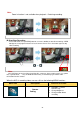
Start Up Screen Main Page 6.1 Quick NVR Setup using Kalay Cam 1. In MAIN PAGE, 2 modes – LIVE and DEVICE – are available. Default is LIVE mode 2. Click [DEVICE] to Camera mode screen 3. Then click [+] sign to add NVR. Maximum allow user to add 4 NVRs. 4. Scan QR-code containing UUID 5. Enter the password. User may also change the name of the NVR for easy identification.
6. Wait the APP search for LCD-NVR and adds to the device list 7. Click the LEFT-side of added LCD-NVR to start Live View. Note: Camera #1 of NVR is displayed by default 8. Rotate smartphone 90 to view in landscape mode (Full Screen) 9.
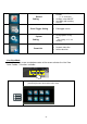
Pan After zoom in, swipe on the display to pan the video 6.
Channel Select By default, camera #1 is displayed when NVR is added User can view another channel of the NVR o Click [Channel Select] icon to get the channel drop list o Click the desired channel to change the Live View channel display Video Record Click to START; or click to STOP video recording Record duration is shown on screen Video are stored locally in smartphone’s memory storage with directory named as “/Record” Snapshot Click to take a snapshot Toast message box indicates snapshot t
6.3 LIVE mode setting Kalay Cam starts at LIVE mode by default In DEVICE mode device list, click [LIVE] tag goes back to LIVE mode In LIVE mode screen, camera windows are arranged in pages. Each time when 4 windows in 1 page are all occupied, new page is automatically created, swipe LEFT/RIGHT to see windows in other pages. Add NVR to LIVE mode window 1. Each time user adds a new NVR, Kalay Cam automatically adds the camera to the first available window.
Remove NVR from APP 1. In LIVE or DEVICE mode, click [EDIT] at TOP-RIGHT corner 2. Select one of the window or camera 3. Click the recycle bin icon 4.
Change Camera Click for the Camera List (NVR list) Click on the Camera icon (Top right corner) of the desired NVR Select desired camera channel, then click [OK] to change Note: User may assign the current window i. To another camera of the same NVR; OR ii.
Event List Click to browse list of video file stored in NVR HDD of the selected camera channel T C User may also click on the search option icons (bottom bar), 2 video files search option are available, slide up or down to select: (1) Time search File list is filtered for time period a. Within an hour b. Within a day c. Within a week d. User specified time frame (2) Channel search File list is filtered per camera channel basis a. Channel 1 b. Channel 2 c. Channel 3 d. Channel 4 e.
Local Media File Browse media files (photos & videos) stored in smartphone o Photos – stored in “/Snapshot” directory o Video – stored in “/Record” directory Simply click thumbnails to view photos or video clips. Video clips can be played back both in landscape & portrait mode.
Camera Settings Review NVR information and various options i. Camera information – UID, camera name & password(hidden) ii. Change password 1. Simply enter Old password, New password, New password again 2. Click [OK] to confirm changes iii. Notification Interval Turn notification ON or OFF Iv.Recording Mode Select Recording Mode i.Off – no recording ii.Full Time – Always record iii.
iv. Event Settings Turns Motion Detection On or Off Set Motion Detection sensitivity – LOW, MEDIUM, HIGH, MAX v.
Model – Main Chipset information Version – Firmware version Total Space – HDD total available capacity Free Space – HDD remaining capacity vi. Reconnect Display NVR online status – ONLINE or OFFLINE If OFFLINE, just click to reconnect again vii.
Side-bar Menu Click side-bar menu icon at TOP-LEFT corner to activate the menu 4 menu functions are available: 1. Events Browse and playback video file stored in NVR. a. Click and select NVR to browse video file list b. Click on filename to playback video clips 2. Album Browse media files (photos & videos) stored in smartphone a. Photos – stored in “/Snapshot” directory b. Video – stored in “/Record” directory Simply click thumbnails to view photos or video clips.
3. About Display Kalay Cam version information 4. Exit Click to close Kalay Cam.
SIMPLIFIED EU DECLARATION OF CONFORMITY Hereby, stabo Elektronik GmbH declares that the radio equipment type stabo smart i_control is in compliance with Directive 2014/53/EU. The full text of the EU declaration of conformity is available at the following internet address: http://stabo.de/fileadmin/DoC/DoC_stabo_smart_i_control_DE_EN.
Errors and technical modification reserved, pictures may vary. © 02 / 2018 stabo Elektronik GmbH stabo Elektronik GmbH Münchewiese 16 . 31137 Hildesheim/Germany Tel. +49 (0) 5121-76 20-0 . Fax: +49 (0) 5121- 51 29 79 Internet: www.stabo.de . E-Mail: info@stabo.