DMX Invader 2420 MK II DMX controller user manual
Thomann GmbH Hans-Thomann-Straße 1 96138 Burgebrach Germany Telephone: +49 (0) 9546 9223-0 Internet: www.thomann.de 01.02.
Table of contents Table of contents 1 General information.............................................................................................................. 1.1 Further information........................................................................................................ 1.2 Notational conventions................................................................................................. 1.3 Symbols and signal words..............................................................
General information 1 General information This user manual contains important information on the safe operation of the device. Read and follow all safety notes and all instructions. Save this manual for future refer‐ ence. Make sure that it is available to all persons using this device. If you sell the device to another user, be sure that they also receive this manual. Our products and user manuals are subject to a process of continuous development.
General information Instructions The individual steps of an instruction are numbered consecutively. The result of a step is indented and highlighted by an arrow. Example: 1. Switch on the device. 2. Press [Auto]. ð Automatic operation is started. 3. Cross-references Switch off the device. References to other locations in this manual are identified by an arrow and the speci‐ fied page number. In the electronic version of the manual, you can click the crossreference to jump to the specified location.
Safety instructions 2 Safety instructions Intended use This device is intended to be used to control spot lights, dimmers, light effects, moving heads or other DMX-controlled devices. Use the device only as described in this user manual. Any other use or use under other operating conditions is consid‐ ered to be improper and may result in personal injury or property damage. No lia‐ bility will be assumed for damages resulting from improper use.
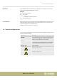
Safety instructions NOTICE! Possible staining The plasticiser contained in the rubber feet of this product may possibly react with the coating of your surface and after some time cause permanent dark stains. In case of doubt, do not put the rubber feet directly on the surface and use a suitable underlay if necessary, i.e. felt-pad floor protectors or similar.
Features 3 Features This DMX controller is specially suited for professional lighting requirements, such as at events, on rock stages, for dance bands, trios and duos as well as for mobile DJ applications.
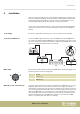
Installation 4 Installation Unpack and check carefully there is no transportation damage before using the unit. Keep the equipment packaging. To fully protect the product against vibration, dust and moisture during transportation or storage use the original packaging or your own packaging material suitable for transport or storage, respectively. Create all connections while the device is off. Use the shortest possible high-quality cables for all connections.
Installation As a prerequisite for this manual control, fixture no. 1 must be activated. The DMX address defines the number of the first DMX control channel of a device (1 - 512).
Connections and operating elements 5 Connections and operating elements Front panel 1 [FOG MACHINE] Activates a connected fog machine (via DMX channel 481). 2 [STROBE] Triggers a connected strobe (via DMX channels 483 & 484). 3 [FIXTURE GROUP] Selects one or multiple fixture groups.
Connections and operating elements 9 [OVERRIDE] Button for subsequently selecting a programmed scene that overrides the running show. 10 [BANK] Button for subsequently selecting a scene. 11 [CENTER] If you have programmed Center positions for a device, and this device is used in the current scene, you can press this button and then use the number buttons [1 – 20] to apply Center positions. 12 [MANUAL/REC] In function mode, this button activates the manual mode.
Connections and operating elements [Fixture] To address up to 20 devices. [Fixture Group] To set up and select up to 20 fixture groups. [Movement] To select 10 programmed movements (buttons 1-10 only). [Preset] To set up and select COLOR presets (buttons [1-10]) and GOBO presets (buttons [11-20]) on up to 20 memory pages. [Cue] To select and programme up to 60 Cues. [Chaser] To select and programme up to 60 Chases. [Override] To select and programme up to 20 Overrides.
Connections and operating elements Number buttons DMX channels Number buttons DMX channels 8 169-192 18 409-432 9 193-216 19 432-456 10 217-240 20 457-480 Rear panel 1 POWER Connect the IEC chassis connector with the fuse holder of the device via the supplied power cord to an AC outlet that provides the voltage specified in the Technical Data. 2 ON / OFF switch Turns the unit on or off. 3 USB USB port for software updates, data backup and importing saved banks.
Operating 6 Operating After switching the Invader on, the console automatically performs a self-test, its pro‐ gress will appear on the display. Once this is completed, the device can be used. 6.1 ‘Setting’ menu Calling up the menu 1. Enter the programming mode by holding down the [PROGRAM] button for 2 seconds. The LED of the [PROGRAM] button flashes when the programming mode is activated. 2. Hold down the [ENTER / MAIN MENU] button for 2 seconds to enter the main menu.
Operating Exiting the menu Press the [ESC / CLEAR] button to return to the previous menu level. Press repeatedly to finally leave the menu. Only after leaving the menu you can exit the programming mode. To do so, keep the [PROGRAM] button pressed for 2 seconds. 6.1.1 Create a new fixture profile If you create profiles for the used device, you can replace the fader channel number in the display by the description for the actual function of the fader on the selected device.
Operating 7. Turn jog wheel # 2 to select the profile collection (‘STAIRVILLE profiles’ or ‘other profiles’) where you want to store the device profile. 8. Press the [ENTER / MAIN MENU], all LEDs blink three times and thereby indicate that you have successfully edited a device profile. 9. Repeat steps 3–8 to create up to 50 device profiles. 10. Press the [ESC / CLEAR] button to return to the previous menu level. 1. Call up the main menu. 2. Turn jog wheel # 1 until ‘02.
Operating 6. Press the [ENTER / MAIN MENU] button to confirm the changed name, or to pro‐ ceed with the function assignment of DMX channels 1-24 without changing the name. 7. Turn jog wheel # 2 to select the field for the desired channel. Turn jog wheel # 4 to change the function assignment for the current channel (e.g., PAN, TILT, DIM, etc.). 8. Repeat steps 3-7 to modify other fixture profiles. 9. Press the [ESC / CLEAR] button to return to the previous menu level.
Operating 6. Press the [ENTER / MAIN MENU] button, all LEDs blink three times, and thus con‐ firm the successful deletion. 7. Repeat steps 3-6 to delete additional device profiles. 8. Press the [ESC / CLEAR] button to return to the previous menu level. 6.1.4 Patch a fixture This feature allows you to assign a previously created profile to one of the Number buttons [1 – 20] that allow you to address the connected devices. 1. Call up the main menu. 2. Turn jog wheel # 1 until ‘04.
Operating 7. Press the [ESC / CLEAR] button to return to the previous menu level. 6.1.5 Reverse channel setup With this function you can reverse individual fader functions so that e.g. pushing a fader upwards triggers a movement clockwise instead of coun‐ terclockwise. 1. Call up the main menu. 2. Turn jog wheel # 1 until ‘05. Reverse channel setup’ is displayed. Press the [ENTER / MAIN MENU] button to activate this function. 3.
Operating 6.1.6 Fade mode select Here you can configure for which channels programmed fade times are considered in automatic mode shows. 1. Call up the main menu. 2. Turn jog wheel # 1 until ‘06. Fade mode select’ is displayed. Press the [ENTER / MAIN MENU] button to activate this function. 3. Turn jog wheel # 2 to switch from the default setting ‘[only pan/tilt]’ to ‘[pan/ tilt + CH select]’ or ‘[all channel]’ . 4. Press the [ENTER / MAIN MENU] button to confirm the setting.
Operating 6.1.7 Blackout mode select 1. Call up the main menu. 2. Turn jog wheel # 1 until ‘07. Blackout mode select’ is displayed. Press the [ENTER / MAIN MENU] button to activate this function. 3. Turn jog wheel # 2 to switch from the default setting ‘[stand by]’ to ‘[pan/tilt center]’ or ‘[black out scene]’ . • ‘[stand by]’ = the console has no output function anymore • ‘[pan/tilt center]’ = all values except for PAN & TILT are set to 0 • ‘[black out scene]’ = all values are set to 0 4.
Operating 6.1.9 Chase run by inside / outside time In this menu you can select whether the chase run is controlled by the time values used during programming the individual scenes, or the timing should be determined only during the chase run. 6.1.10 1. Call up the main menu. 2. Turn jog wheel # 1 until ‘09. Chase run by inside/outside time’ is displayed. Press the [ENTER / MAIN MENU] button to activate this function. 3. Rotate jog wheel # 2 to select ‘[inside time]’ or ‘[outside time]’ .
Operating 4. Then use jog wheel # 2 to select the device number from 001-170 and press the number buttons [1 – 20] to select the desired address. All LEDs blink three times to confirm, and the address of the respective device is displayed. This means that the corresponding address has been transferred to the device. Proceed accordingly using jog wheel # 4. 6.1.11 5. Repeat steps 3–4 to enter the addresses of other devices. 6. Press the [ESC / CLEAR] button to return to the previous menu level.
Operating 8. Press the [ESC / CLEAR] button to return to the previous menu level. You should save a backup of the current show before loading programme files. As the programme file that you load will overwrite all programmes in the controller. So please save the files on a USB drive and / or on a computer and only load files that you really want to use. 6.1.12 Writing to a USB drive You can save the finalized programmes in the directory DIR 2420 on a USB drive.
Operating 6.1.13 7. Press the [ESC / CLEAR] button to return to the previous menu level. 1. Call up the main menu. 2. Turn jog wheel # 1 until ‘13. Modify password’ is displayed. Press the [ENTER / MAIN MENU] button to activate this function. 3. Rotate jog wheel # 2 to toggle between ‘power on password’ , default setting) and ‘memory protect password’ . Press the [ENTER / MAIN MENU] button to acti‐ vate the selected function. 4.
Operating 6.1.14 Enable / disable the password 1. Call up the main menu. 2. Turn jog wheel # 1 until ‘14. Enable password’ is displayed. Press the [ENTER / MAIN MENU] button to activate this function. 3. Turn jog wheel # 1 to select the ‘user power’ password or the ‘user memory protect’ password. Press the [ENTER / MAIN MENU] button to confirm the selec‐ tion.
Operating 6.1.15 6.1.16 Erase all memory 1. Call up the main menu. 2. Turn jog wheel # 1 until ‘15. Erase all memory’ is displayed. Press the [ENTER / MAIN MENU] button to activate this function. 3. If you have protected the memory contents of the device with a password, the device prompts you now to enter the current six-digit password using the number buttons [1-10] (‘10’ stands for ‘0’). Confirm the input with the [ENTER / MAIN MENU] button.
Operating 4. 6.1.17 Press the [ENTER / MAIN MENU] button to save the setting and return to the main menu. To return to the main menu without any changes, press the [ESC / CLEAR] button. Channel value display mode This function lets you select, whether the values for the channels are dis‐ played in a range of ‘0-100’ or ‘0-255’ . 1. Call up the main menu. 2. Turn jog wheel # 1 until ‘17. Channel value display mode’ is displayed. Press the [ENTER / MAIN MENU] button to activate this function. 3.
Operating Number button DMX address Number button DMX address 4 activates unit DMX address 73 with 14 activates unit DMX address 313 with 5 activates unit DMX address 97 with 15 activates unit DMX address 337 with 6 activates unit DMX address 121 with 16 activates unit DMX address 361 with 7 activates unit DMX address 145 with 17 activates unit DMX address 385 with 8 activates unit DMX address 169 with 18 activates unit DMX address 409 with 9 activates unit DMX address 193 with 19 activates
Operating 4. When the desired scene is finalised, press the [MANUAL/REC] button to initiate the saving. 5. Press the [BANK] button and turn Jog wheel # 1 to select the memory bank (1– 60), in which the scene is to be stored. Each bank can store up to 20 scenes. 6. Now the LEDs of those number buttons light up where scenes have already been assigned to. Press the desired number button [1 – 20] where the scene is to be stored. Already occupied memory slots are overwritten without prompting.
Operating 5. Next, you have to set the MOVEMENT parameters to adapt the motion for your particular application. To do so, turn jog wheel # 2 to select the parameters for the desired movement. With jog wheels # 3 & # 4 you can set the values of these parameters.
Operating 4. Now press the [FIXTURE] button and then the number button [1 – 20] for that device participating in the scene whose settings or effect you want to change. 5. Now you can move the faders to change the functions of each channel. ‘Pan’ & ‘Tilt’ can also be adjusted using jog wheels # 1–# 4, or use the [MOVEMENT] button to utilize the MOVEMENT function. 6. If desired, repeat steps 4–5 to change the settings of other participating units in the scene.
Operating 4. Then press the [MANUAL/REC] button to initiate the saving. The LEDs of the buttons CUE, OVERRIDE, CENTER, FIXTURE GROUP, PRESET, CHASE, BANK and BLACK OUT are flashing. 5. Press the [BANK] button. Then rotate jog wheel # 1 to select the bank to which you want to copy the scene. 6. Press a number button [1 – 20] to copy the scene to the desired position. All LEDs will flash three times briefly, thus indicating that this step has been com‐ pleted successfully.
Operating 6.2.6 Copying a bank 1. Call up the programming mode. 2. Press the [BANK] button. 3. Turn jog wheel # 1 to select the bank to be copied.. 4. Then press the [MANUAL/REC] button to initiate the saving, the LEDs of the but‐ tons CUE, OVERRIDE, CENTER, FIXTURE GROUP, PRESET, CHASE, BANK and BLACK OUT are flashing. 5. Then rotate jog wheel # 1 to select the bank number to which the bank to be copied should be saved. 6.
Operating 1. Call up the programming mode. 2. Press the [CHASE] button. Turn jog wheel # 1 to select the number of the memory page on which the chase should be saved. 3. Press the desired number button [1 – 20] where the chase is to be stored. The LED of the [BANK] button lights up and the display shows the number and the chase parameters for BANK, SCENE, STEP, FADE and WAIT.
Operating 4. Turn jog wheel # 1 to select the number of the bank, whose scenes you want to programme into a Chase. 5. Turn jog wheels # 3 & # 4 to adjust the Fade and Wait Time for the current chase. 6. Press the [MUSIC/BANKCOPY] button. 7. Press the [MANUAL/REC] button, all LEDs blink three times and all scenes of the selected bank have now been added to the current Chase. 8. You can now either add individual scenes as described in steps 4–6 in the pre‐ vious section ( Ä Chapter 6.2.
Operating 6.2.10 5. Rotate jog wheel # 1 to select the bank that contains the scene that you want to insert. Press the number button [1 – 20] of the scene to be added to the chase in the current step. 6. Turn jog wheels # 3 & # 4 to adjust the FADE and WAIT TIME for the current scene. If you don't adjust these settings, the device will take over the most recently used values for FADE TIME and WAIT TIME. 7. Press the [MANUAL/REC] button.
Operating 6.2.11 6. Turn jog wheel # 1 to select the bank that contains the scene to be inserted. 7. Press the number button [1 – 20] of the scene you want to insert. 8. Turn jog wheel # 3 to adjust the FADE TIME for the current Chase. Turn jog wheel # 4 to adjust the WAIT TIME for the current Chase. If you don't adjust these settings, the device will take over the most recently used values for FADE TIME and WAIT TIME. 9. Press the [MANUAL/REC] button.
Operating 6.2.12 6.2.13 5. Press the [AUTO/DEL] button. All LEDs flash three times and thus indicate the successful deletion of a scene. 6. Repeat steps 4–5 to delete further scenes from the Chase. 1. Call up the programming mode. 2. Press the [CHASE] button. Turn jog wheel # 1 to select the memory page on which the chase you want to delete has been saved. 3. Hold down the [AUTO/DEL] button while pressing the number button [1 – 20] of the Chase to be deleted.
Operating 5. Press the [PRESET] button. 6. Rotate the jog wheel # 1 to select the number of the preset group 1 – 20, to which the current settings for colour and gobo wheel are to be saved. 7. Press one of the number buttons [1 – 10] to save the colour settings as a COLOR preset, or press one of the number buttons [11 – 20] to save the gobo settings as a GOBO preset.. All LEDs flash three times and thus indicate the suc‐ cessful saving of a preset.
Operating 5. Press the [FIXTURE] button. 6. Press the number button [1 – 20] of the device whose setting you want to change. 7. Use faders 1–24 to change the COLOR and GOBO channel values. 8. Press the [MANUAL/REC] button - now the LEDs of the buttons CUE, OVERRIDE, CENTER, FIXTURE GROUP, PRESET, CHASE, BANK and BLACK OUT are flashing. 9. Press the [PRESET] button. 10. Press that number button [1 – 20] that you have used to open the preset in step 4.
Operating 6.2.16 5. Press the number button [1 – 20] to select the number for the fixture group. All LEDs flash three times to confirm. 6. Repeat steps 2-5 to create further fixture groups. 1. Call up the programming mode. 2. Press the [FIXTURE GROUP] button. 3. Press the number button [1 – 20] to select the number of the fixture group that you want to edit. 4. Press the [FIXTURE] button. Now all LEDs of the fixtures belonging to this group light up. 5.
Operating 6.2.17 6.2.18 Deleting a fixture group 1. Call up the programming mode. 2. Press the [FIXTURE GROUP] button. 3. Hold down the [AUTO/DEL] button while pressing the number button [1 – 20] of the Fixture group to be deleted. All LEDs flash three times and thus indicate the successful deletion of the Fixture group. 4. Repeat steps 2-3 to delete further fixture groups. 1. Call up the programming mode. 2. The LED of the [FIXTURE] button should light up now.
Operating 6.2.19 Center editing 1. Call up the programming mode. 2. Press the [CENTER] button. 3. Press the number button [1 – 20] to select the number of the Center position to be edited. 4. Press the [FIXTURE] button. 5. Press the number button [1 – 20] to select the respective units to be edited. 6. Use the channel faders or the jog wheels # 1 – # 4 to adjust the desired Center position for the functions PAN and TILT (FINE). 7.
Operating 6.2.20 6.2.21 Deleting a Center 1. Call up the programming mode. 2. Press the [CENTER] button. 3. Hold down the [AUTO/DEL] button while pressing the number button [1 – 20] of the Center position to be deleted. All LEDs flash three times and thus indi‐ cate the successful deletion of a Center position. Override programming Overrides are scenes that take precedence over ordinary running scenes.
Operating 6.2.22 6. Press the [OVERRIDE] button. 7. Press the number button [1 – 20] to select the number for the Override to be saved. All LEDs flash three times and thus indicate the successful programming of an Override. 8. Repeat steps 3-7 to programme further Overrides. 1. Call up the programming mode. 2. Press the [OVERRIDE] button. 3. Press the number button [1 – 20] to select the number of the Override to be edited. 4. Press the [FIXTURE] button.
Operating If you have pressed different buttons in steps 3 and 8, the Override you have selected in step 3 will override the Override selected in step 8 including all modifications. 6.2.23 CUE programming Use a cue to run more than one chaser. 6.2.24 1. Call up the programming mode. 2. Press the [CUE] button and turn Jog wheel # 1 to select the number of the memory page on which you want to save the Cue. You can store up to 20 Cues on 3 memory pages, making a total of 60. 3.
Operating 6.2.25 6.2.26 3. Press the number button [1 – 20] of the Cue that you want to edit. The LED of the [CHASE] button as well as the button LEDs of the Chases used in the Cue light up while the Cue runs. The LEDs of those buttons where Chases are stored, that are not used in the Cue, are flashing. Turn jog wheel # 1 to access the Chases stored on other memory pages. 4. Press the number button [1 – 20] to deselect currently used Chases or to add new ones.
Operating 3. Use the channel faders or jog wheels # 1–# 4 to create the desired Blackout scene. 4. Then press the [MANUAL/REC] button to save. Now the LEDs of the buttons CUE, OVERRIDE, CENTER, FIXTURE GROUP, PRESET, CHASE, BANK and BLACKOUT are flashing. 5. Press the [BLACK OUT/STAND ALONE] button. All LEDs flash three times and thus indicate the successful saving of a Blackout scene. 6.3 Function mode After switching on, the LED of the [FIXTURE] button should light up.
Operating 1. Manual mode 1. Press the [BANK] button. Now the ‘MANUAL’ LED should light up. Otherwise press the [MANUAL/REC] button to call up the manual mode. 2. Turn jog wheel # 1 to select the desired bank 1 – 60. The LEDs of those number buttons [1 – 20] where scenes have already been programmed are flashing now. 3. Press the desired number button [1 – 20] to activate the corresponding scenes. 2. Sound-controlled mode 1.
Operating 3. Automatic mode 1. Press the [BANK] button and turn jog wheel # 1 to select the desired bank 1 – 60. 2. Press the [AUTO/DEL] button to call up the automatic mode. The ‘AUTO’ LED lights up. 3. Turn jog wheel # 3 oder # 4 to adjust the current Fade Time or Wait Time. The FADE TIME value determines in what time moving equipment such as Moving Heads complete a change from one scene to the next. The setting range is 0 – 30 s. The WAIT TIME value determines the display duration for this scene.
Operating 2. Press the number button [1 – 20] to select the desired chase. You can also select multiple chases. Their numbers will be indicated in the display. The number of the currently active Chase is flashing then. To activate the respec‐ tively next Chase, press the number button [1 – 20] of the currently active Chase in order to deactivate it. 3. Turn jog wheel # 2 to switch to the previous or next programmed step within the active Chase. 2. Sound-controlled mode 1. Press the [CHASE] button.
Operating 3. Press the [AUTO/DEL] button to call up the automatic mode. The LED of this button lights up then. Now the individual scenes programmed in that Chase run according to their individually programmed values for WAIT and FADE TIME. The device then switches to the next selected Chase, if available. 4. If you have selected ‘CHASE RUN BY INSIDE TIME’ in the SETUP menu, the Chase run is controlled by the values for FADE & WAIT TIME used for the indi‐ vidual scenes in the programming of the chase.
Operating 6.3.3.1 Override control There are 2 ways for you to use the Override control to intervene in automatic pro‐ cesses: Manual Override 1. While CUE, CHASE or BANK scenes are running, press the [OVERRIDE] button. Then press the [FIXTURE] button and subsequently use the number button [1 – 20] to select thedevice whose effect you want to change manually. Move the faders or turn the jog wheels 1 – 4 to modify the effect. 2. To end the Override, press the [OVERRIDE] button.
Operating 4. Press the [ENTER/MAIN MENU] button to save the settings. Press the [PROGRAM] button to leave the menu. 5. Press the [FOG MACHINE] button to blow out fog according to the adjusted parameters. Control Whenever the device automatically triggers the fog output according to the interval setting, the LED in the [FOG MACHINE] button flashes twice briefly. 6.5 Strobe operation 6.5.1 Setting up a DMX strobe 1. Connect a DMX strobe to the DMX signal chain. 2.
Operating Control 5. Press the [STROBE] button to let the Invader control the DMX strobe according to the adjusted values. 6.5.2 Setting up an analogue strobe 1. Connect the strobe to the STROBE output (3) on the rear panel of the unit. 2. Keep the [STROBE] button pressed and press the [PROGRAM] button to open the settings menu. Rotate jog wheel # 2 to adjust the strobe speed for the ana‐ logue strobe. 3. Press the [ENTER/MAIN MENU] button to save the settings.
MIDI functions list 7 MIDI functions list MIDI channel = 1~16 Note number Bank 1 00–19 Turning scene 1–20 of bank 1 on or off Bank 2 20–39 Turning scene 1–20 of bank 2 on or off Bank 3 40–59 Turning scene 1–20 of bank 3 on or off Bank 4 60–79 Turning scene 1–20 of bank 4 on or off Chase 80–99 Turning chase 1–20 on or off CUE 100–119 Turning cue 1–20 on or off 120–125 No function 126 MIDI channel = 0 Blackout MIDI channel Note number 1 00–79 Turning scenes of bank 1–4 on or off
MIDI functions list MIDI channel Note number Command Bank 29–bank 32 8 00–79 Turning scenes of bank 19–32 on or off Bank 33–bank 36 9 00–79 Turning scenes of bank 33–36 on or off Bank 37–bank 40 10 00–79 Turning scenes of bank 37–40 on or off Bank 41–bank 44 11 00–79 Turning scenes of bank 41–44 on or off Bank 45–bank 48 12 00–79 Turning scenes of bank 45–48 on or off Bank 49–bank 52 13 00–79 Turning scenes of bank 49–52 on or off Bank 53–bank 56 14 00–79 Turning scenes of ban
Notes on creating profiles 8 Notes on creating profiles PROFILE.CIF (as the profile cyclostyle) The finished file should use a short name below 8 characters, only use capital letters and the extension ‘CIF’ (the controller does non support long file name). Otherwise the controller can’t read the profile information. IM-1200S.CIF is the profile of ACME IM-1200S Activation of special codes, so that the controller can handle certain channel charac‐ teristics.
Notes on creating profiles ARRT CODE DISPLAY CHANNEL FUNCTION (max. 2 charac‐ ters) (max.
Notes on creating profiles ARRT CODE T TILT TF TILT FINE PT OTHER PAN/TILE CORRELATION CHAN‐ NELS G ALL GOBO CORRELATION CHANNELS C ALL COLOR CORRELATION CHANNELS N ETCAETERAS CHANNELS ARRT CODE DISPLAY (max. 2 char‐ acters) (max.
Notes on creating profiles ARRT CODE DISPLAY CHANNEL FUNCTION (max. 2 char‐ acters) (max.
Notes on creating profiles 1. All characters must be capitalized, except comments after ‘;’. 2. The finished file should use a short name below 8 characters, only use capital letters and the extension ‘CIF’. Otherwise the controller can’t read the profile information. 3. Don’t change the name of the group that contains ‘;********’. 4. Display information should not contain more than 4 characters and no blanks.
Technical specifications 9 Technical specifications Control protocol DMX512 Number of DMX channels 484 Input connections MIDI 2 × DIN connector, 5-pin Audio signal RCA socket, 100 mV, 1 Vpp Voltage supply IEC chassis plug C14 DMX control 2 × XLR chassis socket, 3-pin Stand Alone 2 × XLR chassis socket, 5-pin Voltage supply Connector for power adapter Output connections Power consumption 3.
Protecting the environment 10 Protecting the environment Disposal of the packaging material For the transport and protective packaging, environmentally friendly materials have been chosen that can be supplied to normal recycling. Ensure that plastic bags, packaging, etc. are properly disposed of. Do not just dispose of these materials with your normal household waste, but make sure that they are collected for recycling. Please follow the notes and markings on the packaging.
Musikhaus Thomann · Hans-Thomann-Straße 1 · 96138 Burgebrach · Germany · www.thomann.