
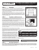
Full Product Manual


Embedment into the wall surface must be adequate to fully secure the fastener, but shall not be less than
1.5” penetration. Individual fasteners should have an ultimate load tensile capacity (pullout) of at least 1,800
pounds, or a working load tensile capacity of 450 pounds. Ultimate load shear capacity (bending) should
be at least 1,700 pounds, or a working load shear capacity of 425 pounds (based on 3000 psi wall mate-
rial). Wall materials less than 3000 psi may require deeper embedment to achieve required pullout and
bending values. Seal/waterproof holes with an exterior grade structural adhesive when anchoring into hol-
low core masonry units. Attach a 12” horizontal brace under each side panel (see Figure 5). (Note: Brace
not supplied with window well, use 2x4 or 2x6 lumber.)
Buck Mount Configuration Mounted to Metal Window Pouring Bucks with Back-Out Screws:
Use all back-out screws available on the buck. If the top and bottom holes extend above and below the
buck use fasteners as indicated for wall mounting and secure the very top and the very bottom of the side
panel flanges directly to the foundation wall. There must be a minimum of six (6) attachment points per
flange including those provided on the window buck.
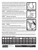
STEP 4 Attaching the Step Sections:
Step sections have open slots at each end which snap onto the protruding tabs located on the side pan-
els. Push the step into the notches above the tabs (both sides at the same time), and force the step slots
over the panel tabs until the step “snaps” into place (see Figure 3). Use (2) 2-1/2” long plated deck screws
(four per step panel) to cross-pin the steps to the side panels at each step/side panel connection (see
Figure 4) (Note: Screws not supplied with window well). Reference the pre-marked locations for cross pin-
ning. This will ensure that the step will not detach during backfilling.
STEP 5 Assembly Bracing:
In addition to the horizontal side bracing mentioned in STEP 3, vertical bracing must be provided to pre-
vent the well from pulling away from the foundation during backfilling. Use (2) wood T-braces measured to
fit vertically from firm soil at the bottom of the excavated opening to where the bottom step attaches to the
side panels (see figure 5).
In order for the optional cover to fit, the ScapeWEL window well must be installed within a one inch (1”)
overall tolerance. Proper cross bracing prior to backfilling will ensure that the well will be square. Using a 2
x 4 as a guide, add both diagonal measurements and divide by two to obtain the desired diagonal brace
length. After cutting the first diagonal brace and placing it above the second step, recheck the second diag-
onal for length before cutting. The two 2 x 4 cross braces must be the same length. Place the second diag-
onal brace on top of the first (see Figure 5). (NOTE: Braces not supplied with window well, use 2 x 4 or 2
x 6 lumber.)
STEP 6 Backfilling:
If sandy soil exists, line the opening with a permanent barrier (such as house wrap) to restrict sand from
washing into rock. FAILURE TO PROPERLY BACKFILL WILL VOID WARRANTY
OUTSIDE of Well: Backfill evenly by hand on all sides as the hole is filled in; Do not do one side at a time.
Always use 3/4” clean free-draining rock or A6 stone completely around the well at least 12” in width to iso-
late the well from the earth. Fill area to within 4” of top step panel. This will keep window well movement to
a minimum during cold weather freeze/thaw conditions and settling soil. Do not use expansive soils, frozen
soils, material that has debris, or organic material.
INSIDE of Well: Place the free-draining rock in the bottom of the well to within 1” of the window sill as
described in Step 1 (Sub-drainage). Make sure that the free draining rock fills the space directly under the
side panels to the bottom of the excavation to provide additional support. Do not settle material around the
well with water. Place planting soil or free draining rock between steps by hand. Note: Sides and steps are
provided with a slight curvature that may straighten after backfilling which is normal and acceptable.
General Care and Maintenance:
The exposed surfaces can be cleaned with a mild nonabrasive cleaner and potable water. Follow manu-
facturer’s limitations noted on the cleaner to make sure that polyethylene is an acceptable surface.
ScapeWEL window wells are finished building product and must be protected from damage during the
remaining construction process. All construction equipment must be kept 2 feet away from the well during
construction.
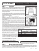
Window Well Models:
Figure 3
Figure 4
Figure 5
SNAP
SCREW
CROSS BRACE LENGTH
VERTICAL
T-BRACE
HORIZONTAL
SIDE
BRACE
The Bilco Company
P.O. Box 1203
New Haven, CT 06505
MSC303 Rev. 9 062106
Call 1-800-854-9724
Monday - Friday 8:15 A.M. - 5:00 P.M. E.S.T.
or log on to www.bilco.com
Installation
Questions?
Model
No. of
Tiers
Inside
Width
Projection From
Foundation
Extension
Model No.
4048-42 2 42” 41” 48” X X 42” 38” 4042C CG1
4048-54 2 54” 41” 48” X X 54” 50” 4054C CG2
4048-66 2 66” 41” 48” X X 66” 62” 4066C CG3
4862-42 3 42” 49” 62” 81” 3019-42 42” 38” 4842C CG4
4862-54 3 54” 49” 62” 81” 3019-54 54” 50” 4854C CG5
4862-66 3 66” 49” 62” 81” 3019-66 66” 62” 4866C CG6
Height* of Side Panels
Standard With Extension
Maximum Width of Opening Optional Cover Models
Wall Mount Buck Mount Dome Metal Grate
* Side panels must extend 4” above grade level and 3-1/2” below the window sill