Owner's Manual ! WARNING ! Exercise can present a health risk. Consult a physician before beginning any exercise program with this equipment. If you feel faint or dizzy, immediately discontinue use of this equipment. Serious bodily injury can occur if this equipment is not assembled and used correctly. Serious bodily injury can also occur if all instructions are not followed. Keep others and pets away from equipment when in use.
TABLE OF CONTENTS Safety Instructions ...................................... 2 Before You Begin ........................................ 4 Equipment Warning & Notice Labels ........ 5 Hardware Identification Chart .................... 6 Assembly Instructions ................................ 7 Setting Up The Accessories...................... 14 Conditioning Guidelines ........................... 15 Warm-Up and Cool-Down ......................... 16 Operational Instructions ...........................
Call Us First Customer Service 1 (800) 375-7520 www.staminaproducts.com THANK YOU FOR PURCHASING THE BioFLEX 2200 Your BioFLEX 2200 does require assembly. Please follow the assembly steps set forth in this manual. With regular workouts, you will be getting your body into shape and be on your way to achieving a happier and healthier lifestyle. Should you have any questions, please call our Customer Service Department toll-free number, 1 (800) 375-7520 Monday - Thursday, 7:30 A.M. - 5:00 P.M.
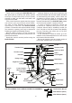
BEFORE YOU BEGIN Thank you for choosing the BioFLEX 2200. We take great pride in producing this quality product and hope it will provide many hours of quality exercise to make you feel better, look better, and enjoy life to its fullest. It's a proven fact that a regular exercise program can improve your physical and mental health. Too often, our busy lifestyles limit our time and opportunity to exercise.
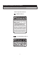
EQUIPMENT WARNING & NOTICE LABELS This chart is provided to help identify the warning & notice labels on the BioFLEX 2200. Please take a moment to familiarize yourself with all of the warning & notice labels. Label is larger than actual size W1 ! WARNING LABEL(72) WARNING Failure to comply with these warnings could result in serious injury or death. All warnings and instructions are to be read prior to use. Replace this warning label if damaged, illegible, or removed.
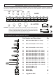
HARDWARE IDENTIFICATION CHART This chart is provided to help identify the hardware used in the assembly process. Place the washers or the ends of the bolts or screws on the circles to check for the correct diameter. Use the small scale to check the length of the bolts and screws. 3/16" 1/4" 5/16" 3/8" 1/2" INCHES 0 0 1/2 10 1 20 1/2 30 40 2 50 1/2 60 3 70 1/2 80 90 4 1/2 5 1/2 100 110 120 130 140 150 MILLIMETERS 6 8 10 6 in. mm.
ASSEMBLY INSTRUCTIONS Place all parts from the box in a cleared area and position them on the floor in front of you. Remove all packing materials from your area and place them back into the box. Do not dispose of the packing materials until assembly is completed. Read each step carefully before beginning. If you are missing a part please call our toll-free number for assistance 1-800-375-7520 or e-mail us at customerservice@staminaproducts.com.
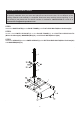
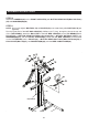
ASSEMBLY INSTRUCTIONS STEP 4 Attach the TOP BEAM(5) to the UPRIGHT(4) with BUTTON HEAD BOLTS(M10x1.5x15mm)(60) and WASHERS(M10)(70). STEP 5 Attach the CROSSING BAR(7) and FRONT SUPPORT(6) to the UPRIGHT(4) with BUTTON HEAD BOLTS(M10x1.5x110mm)(65), WASHERS(M10)(70), NYLOCK NUTS(M10x1.5)(68), LOCK WASHERS(M10)(71), and BUTTON HEAD BOLTS(M10x1.5x60mm)(62). Do not tighten the bolts. STEP 6 Attach the FRONT SUPPORT(6) to the BASE FRAME(1) with BUTTON HEAD BOLTS(M10x1.5x15mm) (60) and WASHERS(M10)(70).
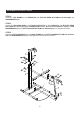
ASSEMBLY INSTRUCTIONS STEP 7 Attach the TENSION POSTS(8) to the back of the TOP BEAM(5) with BUTTON HEAD BOLTS (M10x1.5x50mm)(61), LOCK WASHERS(M10)(71) and WASHERS(M10)(70). STEP 8 Slide the LEFT and RIGHT FORCE ARMS(9, 10) onto the shafts on UPRIGHT(4) and secure with WASHERS(M10)(70) and NYLOCK NUTS(M10x1.5)(68). Do not over tighten the nuts, as the LEFT and RIGHT FORCE ARMS(9, 10) must be able to pivot smoothly.
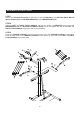
ASSEMBLY INSTRUCTIONS STEP 10 Attach the HANDRAIL(20) to the FRONT SUPPORT(6) with BUTTON HEAD BOLTS(M8x1.25x15mm) (55) and WASHERS(M8)(69). STEP 11 NOTE: Do not over tighten BOLTS(56, 59) as PULLEYS(23) must rotate freely after BOLTS(56, 59) are tightened. Run the Eyelet End of the LAT BAR CABLE(25), 2050mm (80.7”) long, through the slot at the top end of the TOP BEAM(5). Attach the BALL END of the LAT BAR CABLE(25) to the TOP BEAM(5)with a PULLEY(23), a BUTTON HEAD BOLT(M8x1.
ASSEMBLY INSTRUCTIONS STEP 12 Hook a PULLEY SET(29) to one of the hooks on the end of the CROSSING BAR(7). Run the Eyelet End of the CABLE(28), 3980mm (156.7”) long, through the PULLEY SET(29). Run the Eyelet End of the CABLE(28) through another PULLEY SET(29). Hook the PULLEY SET(29) to the hook on the BASE FRAME(1). Attach the CABLE(28) to the Bracket on the LEFT FORCE ARM(9) with a PULLEY(23), a PULLEY COVER(74), a BUTTON HEAD BOLT(M8x1.25x80mm)(57), a WASHER(M8)(69), and a NYLOCK NUT (M8x1.25)(67).
ASSEMBLY INSTRUCTIONS STEP 13 Hook the SEAT FRAME(11) onto one of the Lugs on the FRONT SUPPORT(6) and secure with the LOCKING KNOB(16) and WASHER(M10)(70). NOTE: The three Lugs on the FRONT SUPPORT(6) allow the SEAT FRAME(11) to be attached in three different positions. Start with one of the center positions and adjust if necessary. Use the upper position if users are taller than average. Use the lower position if users are shorter than average.
ASSEMBLY INSTRUCTIONS STEP 16 Attach the LEG LIFT(12) to the SEAT FRAME(11) with BUTTON HEAD BOLT(M10x1.5x65mm)(63), WASHERS(M10)(70), and NYLOCK NUT(M10x1.5)(68). Do not over tighten the bolt, as the LEG LIFT(12) must be able to pivot smoothly. STEP 17 Slide a FOAM PAD(15) onto a PAD TUBE(14) and screw a SECURING CAP(44) into the end of the PAD TUBE(14). Then insert the other end of the PAD TUBE(14) through the hole in the SEAT FRAME(11).
SETTING UP THE ACCESSORIES LAT BAR(36) Attach the LAT BAR(36) to the LAT BAR CABLE(25), with the warning label to the front, with a QUICK LINK(39). Then store the LAT BAR(36) in the hooks provided on the TOP BEAM(5). For some exercises, the CHAIN(41) should be attached between the LAT BAR(36) and the LAT BAR CABLE(25) with two QUICK LINKS(39). NOTE: Adjust the length of the CHAINS(41) between the LAT BAR(36) and the LAT BAR CABLE(25).
CONDITIONING GUIDELINES How you begin your exercise program depends on your physical condition. If you have been inactive for several years or are severely overweight, start slowly and increase your workout time gradually. Increase your workout intensity gradually by monitoring your heart rate while you exercise. Remember to follow these essentials: Have your doctor review your training and diet programs. Begin your training program slowly with realistic goals that have been set by you and your physician.
WARM-UP and COOL-DOWN Warm-Up The purpose of warming up is to prepare your body for exercise and to minimize injuries. Warm up for two to five minutes before strength training or aerobic exercising. Perform activities that raise your heart rate and warm the working muscles.
OPERATIONAL INSTRUCTIONS BioFLEX 2200 RESISTANCE DIAGRAM 1 2 3 4 A B C D E F G BioFLEX 2200 RESISTANCE CHART The BioFLEX™ cable system provides user defined workout movements while utilizing lower amounts of resistance to simulate actions performed in everyday activities. All resistances below are approximate and measured in pounds. Resistance may be more or less depending on how much tension is placed on the bands. ATTACHMENT LOOPS TENSION CORDS A B C D 1 20.5 17.5 15.0 10.0 18.0 15.
TRAINING TIPS 1. Always warm up for at least 5 minutes before doing resistance training. 2. On your first set of exercises, keep the resistance light. 3. Stretching is recommended after the warm up or at the end of the workout. 4. Repetitions for training effects: Muscular Endurance- 12 to 15 repetitions with light resistance Strength & Endurance- 8 to 12 repetitions with medium to heavy resistance Strength- 1 to 8 repetitions heavy resistance 5.
WORKOUT INSTRUCTIONS Calf Raises Single Leg Kick Back Standing Hip Abduction Standing Hip Adduction Seated Ankle Eversion Seated Ankle Inversion Seated Chest Press 19 Incline Chest Press
WORKOUT INSTRUCTIONS Chest Fly Lat Bar Pulldown SIngle Arm Pulldown Standing Row Standing Straight Arm Pulldown Seated Shoulder Press Shoulder Shrugs 20 Upright Row
WORKOUT INSTRUCTIONS Seated Front Raise Seated Lateral Raise Rotator Cuff-Low External Rotation Rotator Cuff-Internal Rotation Rotator Cuff-High External Rotation Standing Biceps Curl Seated Wrist Curl 21 Standing Triceps Pushdown
WORKOUT INSTRUCTIONS Reverse Grip Triceps Pushdown Single Arm Triceps Pushdown Single Arm Triceps Kickback Ab Crunch Oblique Crunch Standing Trunk Rotation Side Bend 22
STORAGE 1. To store the BioFLEX 2200, simply keep it in a clean dry place. 2. To move the BioFLEX 2200, hold the upright of the BioFLEX 2200 while you tip it backward. When the WHEELS(32) come in contact with the floor you can easily roll the BioFLEX 2200. MAINTENANCE The safety and integrity designed into the BioFLEX 2200 can only be maintained when the BioFLEX 2200 is regularly examined for damage and wear. Special attention should be given to the following: 1.
PRODUCT PARTS DRAWING BACK 24 FRONT
PARTS LIST PART# 1 2 3 4 5 6 7 8 9 10 11 12 13 14 15 16 17 18 19 20 21 22 23 24 25 26 27 28 29 30 31 32 33 34 35 36 37 38 39 40 41 42 43 44 45 46 47 PART NAME QTY Base Frame Base Plate Lower Upright Upright Top Beam Front Support Crossing Bar Tension Post Left Force Arm Right Force Arm Seat Frame Leg Lift Leg Lift Bushing Pad Tube Foam Pad Locking Knob Mounting Plate Seat Back Cushion Handrail Foam Tube Hook Sleeve Pulley Pulley Spacer Lat Bar Cable w/ Ball End (2050mm)(80.
PARTS LIST PART# 48 49 50 51 52 53 54 55 56 57 58 59 60 61 62 63 64 65 66 67 68 69 70 71 72 73 74 75 76 77 78 79 PART NAME QTY Round Plug (50.8mm) Square Plug (38mm) / for 1.5 thick tube Square Plug (38mm) / for 2.0 thick tube Rectangular Plug (50mm x 100mm) Bolt, Round Head (M6 x 1 x 15mm) Bolt, Flat Head (M8 x 1.25 x 20mm) Bolt, Flat Head (M8 x 1.25 x 50mm) Bolt, Button Head (M8 x 1.25 x 15mm) Bolt, Button Head (M8 x 1.25 x 45mm) Bolt, Button Head (M8 x 1.25 x 80mm) Bolt, Button Head (M8 x 1.
LIMITED WARRANTY MODEL 50-0220 WARRANTY Stamina Products, Inc. warrants that this product will be free from defects in materials and workmanship under normal use, service and proper operation for a period of 90 days on the parts and three years on the frame from the date of the original purchase from an authorized retailer.
NOTES 28
NOTES 29
FAX/MAIL ORDERING FORM Please do not return the product. For your convenience, Stamina's Customer Service Department can be reached by email at customerservice@staminaproducts.com or toll free at 1-800-375-7520 (in the U.S.). Should a part be missing or a defective part found, please call us from 7:30 A.M. to 5:00 P.M. Central Time, Monday through Thursday and 8:00 A.M. to 3:00 P.M. on Friday or fill out the fax sheet ordering form below and fax it to (417) 889-8064.