
User's Manual


ASSEMBLY INSTRUCTIONS
9
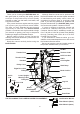
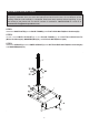
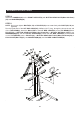
STEP 7
Attach the TENSION POSTS(8) to the back of the TOP BEAM(5) with BUTTON HEAD BOLTS
(M10x1.5x50mm)(61), LOCK WASHERS(M10)(71) and WASHERS(M10)(70).
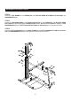
STEP 8
Slide the LEFT and RIGHT FORCE ARMS(9, 10) onto the shafts on UPRIGHT(4) and secure with
WASHERS(M10)(70) and NYLOCK NUTS(M10x1.5)(68). Do not over tighten the nuts, as the LEFT and
RIGHT FORCE ARMS(9, 10) must be able to pivot smoothly.
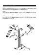
STEP 9
Hook four TENSION CORDS(31) to the four hooks at the top of the TENSION POSTS(8) on both sides.
Hook the lower ends of the TENSION CORDS(31) to the hooks on outer ends of the LEFT and RIGHT
FORCE ARMS(9, 10) on both sides.