Owner's Manual WARNING Exercise can present a health risk. Consult a physician before beginning any exercise program with this equipment. If you feel faint or dizzy, immediately discontinue use of this equipment. Serious bodily injury can occur if this equipment is not assembled and used correctly. Serious bodily injury can also occur if all instructions are not followed. Keep others and pets away from equipment when in use. Always make sure all bolts and nuts are securely tightened prior to each use.
TABLE OF CONTENTS Page Safety Instructions Before You Begin Equipment Warning & Notice Labels Hardware Identification Chart Assembly Instructions Set Up Instructions Operational Instructions Computer Instructions Storage Page Maintenance Conditioning Guidelines Warm-Up and Cool-Down Warranty Product Parts Drawing Parts List Notes Fax/Mail Ordering Form 2 4 5 6 7 13 14 15 18 18 19 20 21 22 23 25 26 SAFETY INSTRUCTIONS WARNING: To reduce the risk of serious injury, read the following Safety Instructions b
CALL US FIRST Customer Service 1(800) 375-7520 www.staminaproducts.com THANK YOU FOR PURCHASING THE Magnetic Fusion 7100 Bike To help you get started, we have pre-assembled most of your Magnetic Fusion 7100 Bike at the factory with the exception of those few parts left unassembled for shipping purposes. Simply follow the few assembly instructions set forth in this manual. With regular workouts, you will be getting your body into shape and be on your way to achieving a happier and healthier lifestyle.
BEFORE YOU BEGIN Thank you for choosing the Magnetic Fusion 7100 Bike. We take great pride in producing this quality product and hope it will provide many hours of quality exercise to make you feel better, look better, and enjoy life to its fullest. It's a proven fact that a regular exercise program can improve your physical and mental health. Too often, our busy lifestyles limit our time and opportunity to exercise.
EQUIPMENT WARNING & NOTICE LABELS This chart is provided to help identify the warning & notice labels on the Magnetic Fusion 7100 Bike. Please take a moment to familiarize yourself with all of the warning & notice labels.
HARDWARE IDENTIFICATION CHART This chart is provided to help identify the hardware used in the assembly process. Place the washers or the ends of the bolts or screws on the circles to check for the correct diameter. Use the small scale to check the length of the bolts and screws. 3/16" 1/4" 5/16" 3/8" 1/2" INCHES 0 1/2 1 1/2 2 1/2 3 1/2 4 1/2 5 1/2 6 in. mm.
ASSEMBLY INSTRUCTIONS Place all parts from the box in a cleared area and position them on the floor in front of you. Remove all packing materials from your area and place them back into the box. Do not dispose of the packing materials until assembly is completed. Read each step carefully before beginning. If you are missing a part please call our toll-free number for assistance 1-800-375-7520 or e-mail us at customerservice@staminaproducts.com.
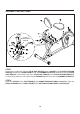
ASSEMBLY INSTRUCTIONS STEP 3 Attach the REAR STABILIZER(6) to the REAR FRAME(5) with CARRIAGE BOLTS(M8x1.25x75mm)(63), ARC WASHERS(M8)(86), LOCK WASHERS(M8)(88), and ACORN NUTS(M8x1.25)(84). STEP 4 Screw the STAND(60) all the way up into the bottom of the FRONT FRAME(1). Connect the PULSE EXTENSION WIRE(40) to the CONTROL WIRE(24). Insert the REAR FRAME(5) onto the FRONT FRAME(1) and secure with BUTTON HEAD BOLTS(M10x1.5x20mm)(66), BUTTON HEAD BOLTS(M10x1.
ASSEMBLY INSTRUCTIONS B. A. (Assembled at the factory) NOTE: Be careful not to damage the PULSE SENSOR WIRES(44) when attaching the HANDRAIL(8) and the SEAT FRAME(7). STEP 5 Refer to illustration A. Attach the HANDRAIL(8) to the SEAT FRAME(7) with CARRIAGE BOLTS (M8x1.25x45mm)(62), ARC WASHERS(M8)(86), LOCK WASHERS(M8)(88), and ACORN NUTS(M8x1.25) (84). STEP 6 Refer to illustration B. Slide the SEAT FRAME(7) onto the REAR FRAME(5) and lock in position with the ADJUSTMENT KNOB(51).
ASSEMBLY INSTRUCTIONS Socket of Pulse Extension Wire(40) STEP 7 Refer to the inset drawing. Plug the PULSE COIL WIRE(42) into the SOCKET of the PULSE EXTENSION WIRE(40) located on the REAR FRAME(5). Clip the GROMMET PLUGS(43) onto both ends of the PULSE COIL WIRE(42). Connect both ends of the PULSE COIL WIRE(42) to the PULSE SENSOR WIRES(44). Push the plugs and excess wires back into the HANDRAIL(8) and secure with the GROMMET PLUGS(43).
ASSEMBLY INSTRUCTIONS STEP 9 NOTE: The RIGHT PEDAL(38) has R stamped on the end of the pedal shaft. The RIGHT PEDAL(38) has right hand threads and is tightened by turning clockwise. The LEFT PEDAL(36) has L stamped on the end of the pedal shaft. The LEFT PEDAL(36) has left hand threads and is tightened by turning counterclockwise. Thread the RIGHT PEDAL(38) into the RIGHT CRANK(33) as shown. Tighten the pedal securely. Select the RIGHT PEDAL STRAP(39) which has R marked on the bottom side of the strap.
ASSEMBLY INSTRUCTIONS STEP 11 Refer to the inset drawing. Run the CONNECTION WIRE(25) through the hole in the plate on the HANDLEBAR(4). Attach the HANDLEBAR(4) to the UPRIGHT(3) with BUTTON HEAD BOLT (M8x1.25x40mm)(64) and FLAT HEAD SCREWS(M6x1x12mm)(69). STEP 12 Install four AA batteries into the COMPUTER(26). Four batteries are included. See page 17 for detailed battery installation instructions. Plug the CONNECTION WIRE(25) into the EXTENSION WIRE on the COMPUTER(26).
SET UP INSTRUCTIONS Place the Magnetic Fusion 7100 Bike in the area where it will be used. It is recommended that the Magnetic Fusion 7100 Bike be placed on an equipment mat. The Magnetic Fusion 7100 Bike is approximately 53 1/4 inches long x 24 1/2 inches wide x 51 3/4 inches tall. (These dimensions may vary up to one inch.) An area 4 feet wide x 7 feet long is required for safe operation of the Magnetic Fusion 7100 Bike.
OPERATIONAL INSTRUCTIONS SEAT ADJUSTMENT Proper seat adjustment is important. There are nine adjustment holes in the REAR FRAME(5). These adjustment holes allow users to adjust the position of the seat for efficient exercise. 1. Rotate the ADJUSTMENT KNOB(51) counterclockwise until the pin releases when the knob is pulled. Pull the ADJUSTMENT KNOB(51) and slide the SEAT FRAME(7) up or down to desired position.
COMPUTER INSTRUCTIONS This computer provides different programs designed to help you meet your fitness goals. Simply choose the program you like, set the time for the workout, and begin exercising. The computer display will show the elapsed time, speed, distance, pulse, and approximate calories burned. MAIN DISPLAY PANEL LCD MONITOR: 1. The LCD displays TIME, SPEED, DISTANCE, CALORIES, PROGRAM, and PULSE. 2. Use the MODE, SET, UP, and DOWN buttons to select a program and time.
COMPUTER INSTRUCTIONS PROGRAM DESCRIPTIONS This computer contains seven different workout programs, P0 to P6. You can preset the program time and the computer will divide the total workout time chosen into 10 intervals. If you do not set the program time in advance, the computer will default to a 30 minute workout time. The load level of each time interval will be shown in the LOAD INDICATOR BAR on the left side of the LCD display.
COMPUTER INSTRUCTIONS COMPUTER OPERATION STEP 1: POWER ON Pedaling or press the MODE button. STEP 2: SET THE PROGRAM Stop pedaling for four seconds. Press the SET button and the display will flash one of the following seven programs, P0, P1, P2, P3, P4, P5, or P6. Use " / " buttons to select a program. Press the SET button when the desired program number appears. You are now ready to set the program time. STEP 3: SET THE PROGRAM TIME 1.
STORAGE 1. To store the Magnetic Fusion 7100 Bike, simply keep it in a clean dry place. 2. Adjust the SEAT FRAME(7) to the lowest position. The Magnetic Fusion 7100 Bike is approximately 53 1/4 inches long x 24 1/2 inches wide x 51 3/4 inches tall. These dimensions will vary. Please measure your Magnetic Fusion 7100 Bike if exact dimensions are needed. 3. To move the Magnetic Fusion 7100 Bike, lift the REAR STABILIZER(6) and the bike will roll on the WHEEL(103) on the FRONT STABILIZER(102). 4.
CONDITIONING GUIDELINES How you begin your exercise program depends on your physical condition. If you have been inactive for several years or are severely overweight, start slowly and increase your workout time gradually. Increase your workout intensity gradually by monitoring your heart rate while you exercise. Remember to follow these essentials: Have your doctor review your training and diet programs. Begin your training program slowly with realistic goals that have been set by you and your physician.
WARM-UP and COOL-DOWN Warm-Up The purpose of warming up is to prepare your body for exercise and to minimize injuries. Warm up for two to five minutes before strength training or aerobic exercising. Perform activities that raise your heart rate and warm the working muscles.
LIMITED WARRANTY MODEL 15-7100B WARRANTY Stamina Products, Inc. warrants that this product will be free from defects in materials and workmanship under normal use, service and proper operation for a period of 90 days on the parts and five years on the frame from the date of the original purchase from an authorized retailer.
PRODUCT PARTS DRAWING FRONT BACK 22
PARTS LIST PART# 1 3 4 5 6 7 8 9 10 11 12 13 14 15 16 17 18 19 20 21 22 23 24 25 26 27 28 29 32 33 34 35 36 37 38 39 40 41 42 43 44 45 46 47 48 49 50 51 52 53 PART NAME Front Frame Upright Handlebar Rear Frame Rear Stabilizer Seat Frame Handrail Pulley and Axle Bearing (6003Z) Bearing Washer (M17) C Ring (17mm) V-Ribbed Belt Idler Arm Idler Wheel Idler Wheel Spacer Tension Spring Magnetic Unit Lock Washer (3/8") Thin Nut (3/8" - 26 x 5/32" thick) Nut (3/8" - 26 x 9/32" thick) Tension Cable Motor Control Wi
PARTS LIST PART# 56 57 58 59 60 61 62 63 64 65 66 67 68 69 70 71 72 73 75 76 77 78 79 80 81 82 83 84 85 86 87 88 89 90 91 92 93 94 95 96 97 98 99 100 101 102 103 104 105 106 PART NAME Foot Stand Leveling Cap Cap Bushing Securing Cap Stand Rectangular Plug (30mm x 60mm) Carriage Bolt (M8 x 1.25 x 45mm) Carriage Bolt (M8 x 1.25 x 75mm) Bolt, Button Head (M8 x 1.25 x 40mm) Bolt, Button Head (M8 x 1.25 x 53mm) Bolt, Button Head (M10 x 1.5 x 20mm) Bolt, Button Head (M10 x 1.5 x 53mm) Bolt, Hex Head (M8 x 1.
NOTES 25
FAX/MAIL ORDERING FORM Please do not return the product. For your convenience, Stamina's Customer Service Department can be reached by email at customerservice@staminaproducts.com or toll free at 1-800-375-7520 (in the U.S.). Should a part be missing or a defective part found, please call us from 7:30 A.M. to 5:00 P.M. Central Time, Monday through Thursday and 8:00 A.M. to 3:00 P.M. on Friday or fill out the fax sheet ordering form below and fax it to (417) 889-8064.