Owner's Manual ! WARNING Exercise can present a health risk. Consult a physician before beginning any exercise program with this equipment. If you feel faint or dizzy, immediately discontinue use of this equipment. Serious bodily injury can occur if this equipment is not assembled and used correctly. Serious bodily injury can also occur if all instructions are not followed. Keep others and pets away from equipment when in use. Always make sure all bolts and nuts are securely tightened prior to each use.
TABLE OF CONTENTS Safety Instructions ...................................... 2 Before You Begin ........................................ 4 Equipment Warning, Caution & Notice Labels ... 5 Hardware Identification Chart .................... 6 Assembly Instructions ................................ 7 Operational Instructions ........................... 11 Storage ....................................................... 13 Maintenance ............................................... Conditioning Guidelines ......
NEED HELP? CONTACT US FIRST 1 (800) 375-7520 customer.care@staminaproducts.com Hi! From all of us here at Stamina Products, thank you for your purchase. We know that you have big fitness goals in mind and we are here to help you along. Call us, email us, or send us a message on Facebook. Be sure to contact us if you have any questions on your new product.
BEFORE YOU BEGIN Thank you for choosing the InMotion® Rower. We take great pride in producing this quality product and hope it will provide many hours of quality exercise to make you feel better, look better, and enjoy life to its fullest. It's a proven fact that a regular exercise program can improve your physical and mental health. Too often, our busy lifestyles limit our time and opportunity to exercise.
EQUIPMENT WARNING, CAUTION & NOTICE LABELS This chart is provided to help identify the warning, caution, and notice labels on the InMotion® Rower. Please take a moment to familiarize yourself with all of the warning, caution, and notice labels. Labels are larger than actual size C1 ! CAUTION LABEL(39) CAUTION For consumer use only. Failure to follow all warnings and instructions could result in injury or property damage.
HARDWARE IDENTIFICATION CHART This chart is provided to help identify the hardware used in the assembly process. Place the washers or the ends of the bolts or screws on the circles to check for the correct diameter. Use the small scale to check the length of the bolts and screws. 3/16" 1/4" 5/16" 3/8" 1/2" INCHES 0 0 1/2 10 1 20 1/2 30 40 2 50 1/2 60 3 70 1/2 80 90 4 1/2 5 1/2 100 110 120 130 140 150 MILLIMETERS 6 8 10 6 in. mm.
ASSEMBLY INSTRUCTIONS Place all parts from the box in a cleared area and position them on the floor in front of you. Remove all packing materials from your area and place them back into the box. Do not dispose of the packing materials until assembly is completed. Read each step carefully before beginning. If you are missing a part, please go to staminaproducts.com under the Customer Care section and order the part needed, e-mail us at customer.care@staminaproducts.
ASSEMBLY INSTRUCTIONS STEP 3 Insert the STOPPER SHAFT(30) through the hole in the CENTER BEAM(2). Screw two STOPPERS(29) onto both ends of the STOPPER SHAFT(30) and tighten at the same time. STEP 4 Attach the REAR SUPPORT(1) to the CENTER BEAM(2) with BUTTON HEAD BOLTS(M8x1.25x15mm) (21) and WASHERS(M8)(12). Press The OVAL CAP(31) into the back end of the CENTER BEAM(2).
ASSEMBLY INSTRUCTIONS STEP 5 Attach the ROWING ARM(43) to the CENTER BEAM(2) with BUTTON HEAD BOLT(M10x1.5x80mm) (26), WASHERS(M10)(27), and NYLOCK NUT(M10x1.5)(28). STEP 6 Connect the SHOCK(10) to one of the adjustment holes on the ROWING ARM(43) and secure with the LOCKING KNOB(44) and the ADJUSTMENT KNOB(45). Refer to detail view B. The shoulder of the LOCKING KNOB(44) and end of the ADJUSTMENT KNOB(45) must be inserted into one of the adjustment holes.
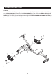
ASSEMBLY INSTRUCTIONS STEP 9 Insert the PEDAL SHAFT(19) through holes located on the CENTER BEAM(2). Slide a PEDAL SPACER(20) and a PEDAL CAP(18) onto each end of the PEDAL SHAFT(19). Then secure the PEDAL CAPS(18) with BUTTON HEAD BOLTS(M8x1.25x15mm)(21) and LARGE WASHERS(M8)(22) at both ends of the PEDAL SHAFT(19). You need to use two Allen Wrenches to tighten the BUTTON HEAD BOLTS(M8x1.25x15mm) (21) at both ends of the PEDAL SHAFT(19) at the same time.
USE INSTRUCTIONS USING THE FITNESS METER POWER ON : Handlebar movement or press any button. POWER OFF : Automatically shuts off after four minutes of inactivity. STROKES /MIN SCAN CNT TIME CAL FUNCTION BUTTONS: MODE : Press to select the function of the lower readout. RESET : To reset all functions to zero. MODE SE RE T FUNCTIONS: COUNT : Upper readout displays the total number of strokes you have taken from zero to 9999 strokes.
OPERATIONAL INSTRUCTIONS LOAD ADJUSTMENT The resistance of the rowing workout can be adjusted by attaching the SHOCK(10) to different adjustment holes on the ROWING ARM(43) with the LOCKING KNOB(44) and ADJUSTMENT KNOB(45). The adjustment hole at the lowest position provides the lowest resistance. The adjustment hole at the highest position provides the highest resistance. To adjust, loosen the ADJUSTMENT KNOB(45) until its end and the shoulder of the LOCKING KNOB(44) complete out from the adjustment hole.
STORAGE 1. To store the InMotion® Rower, simply keep it in a clean dry place. 2. To avoid damage to the electronics meter, remove the battery before storing the InMotion® Rower for one year or more. 3. Grasp the FRONT STABILIZER(3) and REAR SUPPORT(1) to move the InMotion® Rower. Do not use the SEAT(7) to move the InMotion® Rower. The SEAT(7) will move and the SEAT CARRIAGE(5) may pinch your hand or fingers.
CONDITIONING GUIDELINES How you begin your exercise program depends on your physical condition. If you have been inactive for several years or are severely overweight, start slowly and increase your workout time gradually. Increase your workout intensity gradually by monitoring your heart rate while you exercise. Remember to follow these essentials: Have your doctor review your training and diet programs. Begin your training program slowly with realistic goals that have been set by you and your physician.
WARM-UP and COOL-DOWN Warm-Up The purpose of warming up is to prepare your body for exercise and to minimize injuries. Warm up for two to five minutes before strength training or aerobic exercising. Perform activities that raise your heart rate and warm the working muscles. Activities may include brisk walking, jogging, jumping jacks, jump rope, and running in place.
PRODUCT PARTS DRAWING FRONT BACK 16
PARTS LIST PART# PART NAME QTY 1 Rear Support 1 2 Center Beam 1 3 Front Stabilizer 1 5 Seat Carriage 1 6 Handlebar 1 7 Seat 1 8 Meter 1 9 Hand Grip 2 10 Shock 1 11 Bolt, Button Head (M8 x 1.25 x 42mm) 1 12 Washer (M8) 14 13 Nylock Nut (M8 x 1.25) 5 14 Acorn Nut (M8 x 1.
LIMITED WARRANTY MODEL 35-0123B WARRANTY Stamina Products, Inc. (“Stamina”) warrants to the original purchaser that this product will be free from defects in materials and workmanship that arise under normal use, service, proper assembly and proper operation in accordance with product warnings/instructions for a period of 90 days on the parts and one year on the frame from the date of the original purchase from an authorized retailer.
SERVICE TO CONTACT CUSTOMER CARE For your convenience, Stamina’s customer care representatives can be reached by email at customer.care@staminaproducts. com or by phone at 1-800-375-7520 (in the U.S.). Our customer care representatives are available Monday through Thursday from 7:30 a.m. until 5:00 p.m., and Friday 8:00 a.m. until 3 p.m. Central Time. ONLINE CUSTOMER CARE customer.care@staminaproducts.com www.staminaproducts.com TELEPHONE CUSTOMER CARE Tel: 1 (800) 375-7520 MAIL STAMINA PRODUCTS, INC.