Owner's Manual ! WARNING Exercise can present a health risk. Consult a physician before beginning any exercise program with this equipment. If you feel faint or dizzy, immediately discontinue use of this equipment. Serious bodily injury can occur if this equipment is not assembled and used correctly. Serious bodily injury can also occur if all instructions are not followed. Keep others and pets away from equipment when in use. Always make sure all bolts and nuts are securely tightened prior to each use.
TABLE OF CONTENTS Safety Instructions ...................................... 2 Before You Begin ........................................ 4 Equipment Warning, Caution & Notice Labels ... 5 Hardware Identification Chart .................... 6 Assembly Instructions ................................ 7 Operational Instructions ........................... 12 Storage ....................................................... 13 Maintenance ...............................................
Call Us First Customer Service 1 (800) 375-7520 www.staminaproducts.com THANK YOU FOR PURCHASING THE ATS Air Rower 1402 To enact your warranty, please register your product by going to register.staminaproducts.com To help you get started, we have pre-assembled most of your ATS Air Rower 1402 at the factory with the exception of those few parts left unassembled for shipping purposes. Simply follow the few assembly instructions set forth in this manual.
BEFORE YOU BEGIN Thank you for choosing the ATS Air Rower 1402. We take great pride in producing this quality product and hope it will provide many hours of quality exercise to make you feel better, look better, and enjoy life to its fullest. It's a proven fact that a regular exercise program can improve your physical and mental health. Too often, our busy lifestyles limit our time and opportunity to exercise.
EQUIPMENT WARNING, CAUTION & NOTICE LABELS This chart is provided to help identify the warning, caution, and notice labels on the ATS Air Rower 1402. Please take a moment to familiarize yourself with all of the warning, caution, and notice labels.
HARDWARE IDENTIFICATION CHART This chart is provided to help identify the fasteners used in the assembly process. Place the washers or the ends of the bolts or screws on the circles to check for the correct diameter. Use the small scale to check the length of the bolts and screws. 3/16" 1/4" 5/16" 3/8" 1/2" INCHES 0 0 1/2 10 1 20 1/2 30 40 2 50 1/2 60 3 70 1/2 80 4 1/2 5 1/2 90 100 110 120 130 140 150 MILLIMETERS 6 8 10 6 in. mm.
ASSEMBLY INSTRUCTIONS Place all parts from the box in a cleared area and position them on the floor in front of you. Remove all packing materials from your area and place them back into the box. Do not dispose of the packing materials until assembly is completed. Read each step carefully before beginning. If you are missing a part please call our toll-free number for assistance 1-800-375-7520 or e-mail us at customerservice@staminaproducts.com.
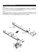
ASSEMBLY INSTRUCTIONS STEP 3 Make sure the wheels on the FRONT STABILIZER(6) face the front. Attach the FRONT STABILIZER(6) to the MAIN FRAME(1) with BUTTON HEAD BOLTS(M8x1.25x55mm)(71), LOCK WASHERS(M8)(34), WASHERS(M8)(35), and ACORN NUTS(M8x1.25)(33).
ASSEMBLY INSTRUCTIONS STEP 4 Locate the C Ring(48) on the STOPPER BAR(56). Insert the longer end of the STOPPER BAR(56) through the MAIN FRAME(1). Secure the STOPPER BAR(56) in position with the SPRING CLIP(46). STEP 5 There is a “L” decal on the LEFT PEDAL CAP(43L), and a “R” decal on the RIGHT PEDAL CAP(43R). Insert the PEDAL SHAFT(45) through the holes on the MAIN FRAME(1).
ASSEMBLY INSTRUCTIONS STEP 6 Slide the SEAT(9) onto the RAIL(8). Attach the STOPPER BUMPERS(66) to the RAIL(8) with NUTS(M8x1.25) (84). Also, please verify that the other STOPPER BUMPER(66) have already been assembled at the factory. If it has not been pre-assembled, then please assemble at this time. STEP 7 Attach the REAR STAND(5) to the RAIL(8) with the SUPPORT PLATES(89), WASHERS(M8)(35), LOCK WASHERS(M8)(34), and BUTTON HEAD BOLTS(M8x1.25x15mm)(57).
ASSEMBLY INSTRUCTIONS STEP 8 Connect the LOWER SENSOR WIRE(90) to the CONNECTION WIRE(85). Attach the RAIL(8) to the MAIN FRAME(1) with BUTTON HEAD BOLTS(M8x1.25x25mm)(51) and WASHER(M8)(35). Lock the RAIL(8) in position by inserting the PULL PIN(54) into the MAIN FRAME(1). Slide the WASHER(ø13xø28x2mm thick)(55) onto the LOCKING KNOB(53), then screw the LOCKING KNOB(53) into the RAIL(8) for more security. STEP 9 Install two AA batteries into the METER(67), the batteries are not included.
OPERATIONAL INSTRUCTIONS USING THE FITNESS METER POWER ON : Seat movement or push the button. POWER OFF : Automatic shut off after two minutes of inactivity. FUNCTION BUTTON: Press to select the function value displays of SPM, DISTANCE, and TIMER, or COUNTER, SPEED, and CALORIES. Reset all functions to zero by pressing the button and holding it down for three seconds. FUNCTIONS: SPM: Displays the current stroke per minute from zero to 9999.
STORAGE 1. To store the ATS Air Rower 1402, simply keep it in a clean dry place. 2. To avoid damage to the electronics, remove the batteries before storing the ATS Air Rower 1402 for one year or more. 3. Move the ATS Air Rower 1402 with the moving wheels on the FRONT STABILIZER(6). Grasp and lift the REAR STAND(5) to move the ATS Air Rower 1402. Do not use the SEAT(9) to move the ATS Air Rower 1402. The SEAT(9) will move and the SEAT CARRIAGE(22) may pinch your hand or fingers. 4.
CONDITIONING GUIDELINES How you begin your exercise program depends on your physical condition. If you have been inactive for several years or are severely overweight, start slowly and increase your workout time gradually. Increase your workout intensity gradually by monitoring your heart rate while you exercise. Remember to follow these essentials: Have your doctor review your training and diet programs.
WARM-UP and COOL-DOWN Warm-Up The purpose of warming up is to prepare your body for exercise and to minimize injuries. Warm up for two to five minutes before strength training or aerobic exercising. Perform activities that raise your heart rate and warm the working muscles.
FRONT PRODUCT PARTS DRAWING BACK
PARTS LIST PART# 1 2 3 4 5 6 7 8 9 10 11 12 13 14 15 16 17 18 19 20 21 22 23 24 25 26 27 28 29 30 31 32 33 34 35 36 37 38 39 40 41 42 43 44 45 46 47 48 49 50 51 52 53 54 55 56 57 58 59 60 PART NAME Main Frame Rail Connector Rail Cap Left Wire Cage Rear Stand Front Stabilizer Left Front Endcap Rail Seat Left Cover S
PARTS LIST PART# 61 62 63 64 65 66 67 68 69 70 71 72 73 74 75 76 77 78 79 80 81 82 83 84 85 86 87 88 89 90 91 92 93 94 95 96 97 98 99 100 101 102 103 104 105 106 107 108 109 110 111 112 113 114 115 116 117 118 119 PART NAME Bolt, Flat socket Head (M8 x 1.25 x 24mm) Roller Spacer (ø8.4 x ø12 x 8mm) Roller Nylock Nut (M8 x 1.
LIMITED WARRANTY MODEL 35-1402 WARRANTY Stamina Products, Inc. warrants that this product will be free from defects in materials and workmanship under normal use, service, proper assembly and proper operation for a period of 90 days on the parts and three years on the frame from the date of the original purchase from an authorized retailer.
NOTES 20
NOTES 21
TO CONTACT CUSTOMER SERVICE For your convenience, Stamina’s customer service representatives can be reached by email at customerservice@ staminaproducts.com or by phone at 1-800-375-7520 (in the U.S.). Our customer service representatives are available Monday through Thursday from 7:30 a.m. until 5:00 p.m., and Friday 8:00 a.m. until 3 p.m. Central Time. ONLINE CUSTOMER SERVICE customerservice@staminaproducts.com www.staminaproducts.