
Instructions / Assembly
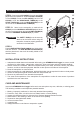

7.
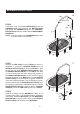
6.
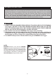
Tip
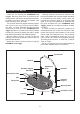
ASSEMBLY INSTRUCTIONS
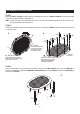
STEP 7
Remove the LEG CAP(7) from the LEG(5) as shown in
illustration 7. Loosen the LOCKING KNOB(19) on the
SENSOR DETECTOR(35) to allow the LEG(5) to slide
through the hole in the SENSOR DETECTOR(35). Slide
the SENSOR DETECTOR(35) on the LEG(5) and slide
up until it touches the rail frame. Adjust the position of
the SENSOR DETECTOR(35) so that the tip is slightly
touching the bottom of the MAT(3). Be sure the SENSOR
DETECTOR(35) is not pressed rmly against the bottom
of the mat or bent downward. If it is not adjusted correctly,
there is a chance that the SENSOR DETECTOR(35) won’t
work properly or that the arm will break during use. Lock the
SENSOR DETECTOR(35) in position with the LOCKING
KNOB(19). Press the LEG CAP(7) back on the LEG(5).
STEP 8
Install a AA battery into the METER(22), battery is not
included. See page 14 for detailed battery installation
instructions. Slide the METER(22) onto the MOUNTING
BRACKET(24). Plug the sensor wire on the SENSOR
DETECTOR(35) into the back of the METER(22).
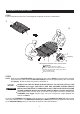
STEP 6
Insert both ends of the TOP HANDRAIL(13) into the
HANDRAILS(15) and lock with the BUTTON PINS
(14). Insert the HANDRAILS(15) into the HANDRAIL
SUPPORTS(16) and lock in position with the ADJUSTMENT
KNOBS(18).
NOTE: There are marks on the HANDRAILS(15) to help
to set the height of the handrail.
9
Mark
Button Pin(14)