
Owner's Manual


ASSEMBLY INSTRUCTIONS
9
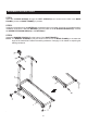
STEP 4
Insert the LOCKING KNOB(5) through the LEFT UPRIGHT(2) and screw into the hole in the BASE
FRAME(1) to lock the BASE FRAME(1) in position.
STEP 5
Install two AAA batteries into the METER(21), the batteries are not included. See page 10 for detailed battery
installation instructions. Slide the METER(21) onto the plate on the U-SHAPED HANDRAIL(4). Connect
the UPPER EXTENSION WIRE(23) to the METER(21).
STEP 6
Attach the BUMPER STANDS(17) to the bottom of the BASE FRAME(1).
NOTE: The BUMPER STANDS(17) may be stored on the end of the BASE FRAME(1) to increase the
angle of the treadmill and reduce the walking resistance. See page 12 for details on adjusting the
walking resistance.