Owner's Manual WARNING Exercise can present a health risk. Consult a physician before beginning any exercise program with this equipment. If you feel faint or dizzy, immediately discontinue use of this equipment. Serious bodily injury can occur if this equipment is not assembled and used correctly. Serious bodily injury can also occur if all instructions are not followed. Keep others and pets away from equipment when in use. Always make sure all bolts and nuts are tightened prior to each use.
TABLE OF CONTENTS Page Safety Instructions Before You Begin Hardware Identification Chart Assembly Instructions Set Up Instructions Operational Instructions Storage Maintenance Page 2 4 5 6 10 11 13 13 Conditioning Guidelines Warm-up and Cool-Down Product Parts Drawing Parts List Warranty Notes Fax/Mail Ordering Form 14 15 16 17 19 20 22 SAFETY INSTRUCTIONS WARNING: To reduce the risk of serious injury, read the following Safety Instructions before using the R360s RECUMBENT BIKE. 1. 2. 3. 4. 5. 6. 7.
CALL US FIRST THANK YOU FOR PURCHASING THE STAMINA R360s RECUMBENT BIKE To help you get started, we have pre-assembled most of your R360s RECUMBENT BIKE at the factory with the exception of those few parts left unassembled for shipping purposes. Simply follow the few assembly instructions set forth in this manual. With regular workouts you will be getting your body into shape and on your way to achieving a happier and healthier lifestyle.
BEFORE YOU BEGIN Thank you for choosing the R360s RECUMBENT BIKE. We take great pride in producing this quality product and hope it will provide many hours of quality exercise to make you feel better, look better and enjoy life to its fullest. Yes, it's a proven fact that a regular exercise program can improve your physical and mental health. Too often, our busy lifestyles limit our time and opportunity to exercise.
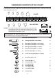
HARDWARE IDENTIFICATION CHART This chart is provided to help identify the hardware used in the assembly process. Place the washers, the end of the bolts, or screws on the circles to check for the correct diameter. Use the small scale to check the length of the bolts and screws. 3/16" 1/4" 5/16" 3/8" 1/2" INCHES 0 1/2 1 1/2 2 1/2 3 1/2 4 1/2 5 1/2 6 in. mm.
ASSEMBLY INSTRUCTIONS Place all parts from the box in a cleared area and position them on the floor in front of you. Remove all packing materials from your area and place them back into the box. Do not dispose of the packing materials until assembly is completed. Read each step carefully before beginning. If you are missing a part please call our toll-free number for assistance 1 (800) 375-7520 or e-mail us at: parts@staminaproducts.com Position the large holes next to the Front Frame(1).
ASSEMBLY INSTRUCTIONS Make the arc indentation face to the front. BOTTOM VIEW STEP 4 NOTE: Install the HEX BOLTS(63) as shown in the illustration above. This allows the head of the bolts to fit inside the hex shape holes in the SEAT FRAMES(5, 6). Attach the RIGHT HANDRAIL(8) to the RIGHT SEAT FRAME(6) with HEX BOLTS(M6x1x35mm)(63), ARC WASHERS(M6)(78), LOCK WASHERS(M6)(80), and ACORN NUTS(M6x1)(73). Repeat on the left side.
ASSEMBLY INSTRUCTIONS STEP 6 Attach the SEAT CUSHION(53) onto the LEFT and RIGHT SEAT FRAMES(5, 6) with ROUND HEAD BOLTS(M6x1x35mm)(60). Attach the BACK CUSHION(54) onto the LEFT and RIGHT SEAT FRAMES(5, 6) with ROUND HEAD BOLTS(M6x1x35mm)(60).
ASSEMBLY INSTRUCTIONS STEP 7 NOTE: The RIGHT PEDAL(43) has R stamped on the end of the pedal shaft. The RIGHT PEDAL(43) has right hand threads and is tightened by turning clockwise. The LEFT PEDAL(42) has L stamped on the end of the pedal shaft. The LEFT PEDAL(42) has left hand threads and is tightened by turning counter clockwise. Thread the RIGHT PEDAL(43) onto the right side of the CRANK(9) as shown. Tighten the pedal securely. Do the same to attach the LEFT PEDAL(42) onto the left side of the CRANK(9).
SET UP INSTRUCTIONS Place the R360s RECUMBENT BIKE in the area where it will be used. It is recommended that the R360s RECUMBENT BIKE be placed on an equipment mat. The R360s RECUMBENT BIKE is approximately 61 3/4" long (max.) x 27 1/2" wide x 36" tall. (These dimensions may vary up to one inch.) An area 4 feet wide x 7 feet long is required for safe operation of the R360s RECUMBENT BIKE. Make sure that adequate space is available for access to and passage around the R360s RECUMBENT BIKE.
OPERATIONAL INSTRUCTIONS USING THE METER POWER ON : Pedal movement or push the MODE button. POWER OFF : Automatic shut off after four minutes of inactivity. MODE BUTTON: Press to select display functions, include SCAN, TIME, SPEED, DISTANCE, CALORIES, and HEART RATE. Press and hold for three seconds to reset all functions to zero.
OPERATIONAL INSTRUCTIONS SEAT ADJUSTMENT Proper seat adjustment is important. 1. Loosen the ADJUSTMENT KNOB(45) and slide the REAR FRAME(3) to adjust the seat. Tighten the ADJUSTMENT KNOB(45) after adjusting the seat to a new position. 2. Sit on the seat and place your feet on the pedals. You should be able to move through a complete pedal stroke without locking your knees or shifting your hips on the seat.
STORAGE 1. To store the R360s RECUMBENT BIKE simply keep it in a clean dry place. 2. Adjust the REAR FRAME(3) into the FRONT FRAME(1) to the shortest position. The R360s RECUMBENT BIKE is approximately 41" long x 27 1/2" wide x 36" tall. These dimensions will vary. Please measure your R360s RECUMBENT BIKE if exact dimensions are needed. 3. Lift the R360s RECUMBENT BIKE from the FRONT STABILIZER(2) and REAR STABILIZER(4) to move. 4.
CONDITIONING GUIDELINES How you begin your exercise program depends on your physical condition. If you have been inactive for several years or are severely overweight, start slowly and increase your workout time gradually. Increase your workout intensity gradually, too, by monitoring your heart rate while you exercise. Remember to follow these essentials: Have your doctor review your training and diet programs.
WARM-UP and COOL-DOWN Warm-up The purpose of warming up is to prepare your body for exercise and to minimize injuries. Warm up for two to five minutes before strength-training or aerobic exercising. Perform activities that raise your heart rate and warm the working muscles.
PRODUCT PARTS DRAWING FRONT BACK 16
PARTS LIST DIAGRAM# 1 2 3 4 5 6 7 8 9 10 11 12 13 14 15 16 17 18 19 20 21 22 23 24 25 26 27 28 29 30 31 32 33 34 35 36 37 38 39 40 41 42 43 44 45 46 47 PART NAME Front Frame Front Stabilizer Rear Frame Rear Stabilizer Left Seat Frame Right Seat Frame Left Handrail Right Handrail Crank Bearing Housing Ball Bearing Inside Bearing Collar Outside Bearing Collar Bearing Washer Bearing Snap Washer Bearing Nut Pulley V-Ribbed Belt Idler Arm Idler Wheel Idler Wheel Spacer Tension Spring Magnetic Unit Eyebolt Tensi
PARTS LIST DIAGRAM# 48 49 50 51 52 53 54 55 56 57 58 59 60 61 62 63 64 65 66 67 68 69 70 71 72 73 74 75 76 77 78 79 80 81 82 83 84 85 86 PART NAME End Stopper Levelling Cap (50mm) Square Plug (25.4mm x 25.4mm) Rectangular Plug (30mm x 60mm) Foam Grip Seat Cushion Back Cushion Washer (M17 x 32mm x 0.5mm thick) Carriage Bolt (M8 x 1.25 x 65mm) Bolt, Button Head (M8 x 1.25 x 55mm) Bolt, Button Head (M10 x 1.5 x 125mm) Bolt, Round Head (M6 x 1 x 15mm) Bolt, Round Head (M6 x 1 x 35mm) Bolt, Flat Head (M8 x 1.
LIMITED WARRANTY MODEL 15-4760 WARRANTY Stamina Products, Inc. warrants that this product will be free from defects in materials and workmanship under normal use, service and proper operation for a period of 90 days on the parts and one year on the frame from the date of the original purchase from an authorized retailer.
NOTES 20
NOTES 21
FAX/MAIL ORDERING FORM Please do not return the product. For your convenience, Stamina has a Customer Service Department with a toll-free number. Should a part be missing or a defective part found, please call 1 (800) 375-7520 (in the U.S.) from 7:30 A.M. to 5:00 P.M. Central Time, Monday through Thursday and 8:00 A.M. to 3:00 P.M. on Friday or fill out the fax sheet ordering form below and fax it to (417) 889-8064.