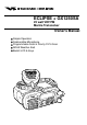
ECLIPSE + GX1250SA 25 watt VHF/FM Marine Transceiver Owner’s Manual Simple Operation Submersible Microphone Programmable Scan & Priority Ch16 Scan NOAA Weather Alert Backlit LCD & Keys IZON STA ND HOR ARD VOL/ PWR
TABLE OF CONTENTS FCC NOTICE .......................................................................................................... 1 1 GENERAL INFORMATION .............................................................................. 3 1.1 INTRODUCTION ................................................................................. 3 1.2 FCC/ INDUSTRY CANADA INFORMATION ....................................... 4 2 ACCESSORIES ..........................................................................
FCC NOTICE IMPORTANT NOTICE The following device operating configurations must be satisfied: — This radio is restricted to occupational use, work related operations only where the radio operator must have the knowledge to control its RF exposure conditions. — The radio must be used with a maximum operating duty cycle not exceeding 50%, in typical Push-to-Talk configurations. — When transmitting, hold the radio in a vertical position with its microphone 1 to 2 inches (2.
NOTICE Unauthorized changes or modifications to this equipment may void compliance with FCC Rules. Any change or modification must be approved in writing by STANDARD HORIZON, a division of VERTEX STANDARD. NOTICE This equipment has been tested and found to comply with the limits for a Class B digital device, pursuant to Part 15 of the FCC Rules. These limits are designed to provide reasonable protection against harmful interference in a residential installation.
1 GENERAL INFORMATION 1.1 INTRODUCTION Congratulations on your purchase of the ECLIPSE+! Whether this is your first marine VHF transceiver, or if you have other STANDARD HORIZON equipment, The STANDARD HORIZON organization is committed to ensuring your enjoyment of this high-performance transceiver, which should provide you with many years of satisfying communications even in the harshest of environments.
1.2 FCC/ INDUSTRY CANADA INFORMATION The following data pertaining to the transceiver is necessary to fill out the license application. Type Acceptance ................................................................... FCC Part 80 Output Power .......................................... 1 Watt (low) and 25 Watts (high) Emission ...................................................................................... 16K0F3E Frequency Range ............................................... 156.025 to 163.
2 ACCESSORIES 2.1 PACKING LIST When the package containing the transceiver is first opened, please check it for the following contents: • GX1250SA ECLIPSE+ Transceiver (White/Black) • CMP349WR/CMP349BR (White/Black Microphone attached to the transceiver) and hanger kit • Mounting Bracket and attaching hardware • Owner’s Manual • Owner’s Manual Supplement • Power Cord 2.2 OPTIONS CMB16 ...................................................................... Flush-Mount Bracket 101S .........................
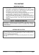
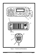
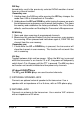
3 CONTROLS AND INDICATORS NOTE This section defines each control of the transceiver. See Figure 1 for location of controls. For detailed operating instructions refer to chapter 4 of this manual. 3.1 CONTROLS AND CONNECTIONS q POWER SWITCH/VOLUME CONTROL Turns the transceiver on and off as well as adjusts the audio volume. When the power is turned on, the transceiver is set to the last selected channel.
q VOL/ PWR STANDARD HORIZON ECLIPSE + SCAN 16 / 9 MEM H/L U.I.C WX SQL w r e t y !0 u i 16/9 o Figure 1.
WX Key Immediately recalls the previously selected NOAA weather channel from any channel location. Secondary use 1. Holding down the 16/9 key while pressing the WX key changes the mode from USA to International or Canadian. 2. Holding down the WX and SCAN key while turning the power on resets the microprocessor and erases scan channels from memory. This clears the memory and establishes the factory-set defaults. For a list of these defaults, see the section on Resetting the Transceiver’s Microprocessor.
y DC INPUT CABLE Connects the transceiver to a DC power supply of 13.8V ± 20 %. u PTT (Push-To-Talk) SWITCH Keys the transmitter when the transceiver is in radio mode. If the transceiver is in the intercom operation mode, it activates the microphone for the intercom. i Submersible MIC This microphone's water-resistant is equivalent to JIS Class 7th. o UP and DOWN KEYS The UP and DOWN on the mic function the same as the The UP and DOWN keys on the front panel of the transceiver.
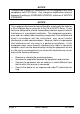
3.2 INDICATORS U WX I C TX HI LO A Figure 2. Indicators The LCD on the transceiver has several symbols and indicators that should be understood by the user before operating the unit. Figure 2 shows all of these symbols and indicators, although it is not possible to see them at the same time. U/I/C Indicator Indicates the mode of operation (USA, International or Canadian) for a particular channel. WX Indicator Indicates a weather channel. TX Indicator Transmission indicator.
7-SEGMENT Display Displays the channel number in use. HI/LO Indicator Indicates the power setting. “HI” 25 watts and “LO” 1 watt. This display is blank if a transmission-inhibited channel is selected.
4 INSTALLATION 4.1 FREQUENCY AND DEVIATION TESTS FCC regulations require that the transceiver’s deviation and frequency be tested before initial installation or operation. This test should be performed by a Certified Marine Technician. 4.2 LOCATION 1. The transceiver can be mounted at any angle.
a. At the rear of the transceiver, connect the antenna cable to the antenna jack. The antenna must have a PL259 connector. RG8 or RG213 coaxial cable must be used if the antenna is 25 feet or more from the transceiver. RG58 cable can be used for distances less than 25 feet. b. Connect the red power cord to a 13.8 VDC ± 20 % power source. Connect the black power cord to negative ground. See Figure 3 for this step . c.
4.4 CMB16 FLUSH MOUNT INSTALLATION 1. Make a rectangular template for the flush mount measuring 2 inches (50 mm) H x 5 3/8" inches (135 mm) W. 2. Use the template to mark the location where the rectangular hole is to be cut. Confirm the space behind the dash or panel is deep enough to accommodate the transceiver (at least 6 inches deep). There should be at least 1/2 inch between the transceiver’s heatsink and any wiring, cables or structures. 3. Cut out the rectangular hole and insert the transceiver. 4.
5 OPERATION 5.1 RECEPTION 1. After the transceiver has been installed, ensure that the power supply and antenna are properly connected. 2. Turn the VOL/PWR knob until the transceiver turns on. 3. Turn the SQL knob fully counterclockwise. This state is known as “squelch off”. 4. Turn up the volume until noise or audio from the speaker is at a comfortable level. 5. Turn the SQL knob clockwise until the random noise disappears. This state is known as the “squelch threshold.” 6.
5.3 TRANSMIT TIME - OUT TIMER (TOT) When the PTT switch on the microphone is held down, transmit time is limited to 5 minutes. This prevents unintentional transmissions. About 10 seconds before automatic transmitter shutdown, a warning beep will be heard from the speaker(s). The transceiver will automatically go to receive mode, even if the PTT switch is continually held down. Before transmitting again, the PTT switch must first be released and then pressed again. 5.
5.6 NOAA WEATHER CHANNELS 1. To receive a NOAA weather channel, press the WX key from any channel. The transceiver will go to the last selected weather channel. 2. Press the UP or DOWN key to select a different NOAA weather channel. 3. To exit from the NOAA weather channels, press the WX key. The transceiver returns to the channel it was on prior to a weather channel. 5.
5.8 MEMORY SCANNING 1. Adjust the SQL knob until background noise disappears. 2. Select a desired channel to be scanned using the UP or DOWN key. Press and hold down the SCAN key until MEM appears on the LCD which programs the channel into the transceivers memory. 3. Repeat step 2 for all the desired channels to be scanned. 4. To DELETE a channel from the transceiver’s memory, select a channel to be erased with the UP or DOWN key. Press and hold down the SCAN key until MEM disappears on the LCD. 5.
6 MAINTENANCE The inherent quality of the solid-state components used in this transceiver will provide many years of continuous use. Taking the following precautions will prevent damage to the transceiver. * Never key the microphone unless an antenna or suitable dummy load is connected to the transceiver. * Ensure that the supply voltage to the transceiver does not exceed 16 VDC or fall below 11 VDC.
6.2 TROUBLESHOOTING CHART TROUBLESHOOTING CHART SYMPTOM PROBABLE CAUSE Transceiver fails to power up. No DC voltage to the transceiver, or blown fuse. Check the power cable for DC voltage, or replace the fuse (6A 250V). Transceiver blows fuse when connected to power supply. Reversed power wires. Make sure the red wire is connected to the positive battery post and the black wire is connected to the negative. If the fuse still blows, contact your STANDARD HORIZON Dealer.
7 SPECIFICATIONS Performance specifications are nominal, unless otherwise indicated, and are subject to change without notice. 7.1 GENERAL Channels ........................................... All USA, International and Canadian Input Voltage .................................................................... 13.8 VDC ± 20% Current Drain Standby ........................................................................................ 0.5A Receive ...........................................................
Marine Division of Vertex Standard US Headquarters 17210 Edwards Rd., Cerritos, CA 90703 Phone 562/404-2700 Fax 800/552/6813 Email marinetech@vxstd.com www.vxstd.