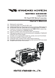
MATRIX GX3000E 25 Watt VHF/FM ITU Class D DSC Marine Transceiver Owner's Manual z z z z z z z z z z z z Waterproof construction Commercial grade ITU Class D DSC VHF Independent Channel 70 receiver built-in for continuous DSC watching 30 W Loud Hailer with listen back and 4 fog horns, Bells & Whistles Capable of connecting 2 optional enhanced CMP25 RAM+ second station remote microphone or VH-310 Handset Intercom between radio and second station microphone DSC position request and send functions with compat
TABLE OF CONTENTS 1 2 3 4 5 6 7 8 9 GENERAL INFORMATION ............................................................................................................ 4 PACKING LIST .............................................................................................................................. 4 OPTIONS ....................................................................................................................................... 4 INSTALLATION NOTE ...................................
TABLE OF CONTENTS 9.5.5 Receiving an Individual Call ...................................................................................... 47 CALL WAITING DIRECTORY ............................................................................................ 47 9.6.1 Enabling the Call Waiting Feature ........................................................................... 47 9.6.2 Reviewing Received Calls Logged into the Call Waiting Directory ..................... 48 9.6.
1 GENERAL INFORMATION The Vertex Standard GX3000E is a VHF/FM transceiver designed for use in the frequency range of 156.025 to 163.275 MHz. The GX3000E can be operated from 11 to 16 VDC and has a switchable RF output power of 1 watt or 25 watts. The GX3000E is a Class D DSC (Digital Selective Calling) VHF and includes a 30W PA with preprogrammed fog signals, bells and whistles. 2 connections are available for the RAM+ or VH-310 second station remote microphones.
4 INSTALLATION NOTE The installation of this equipment should be made in such a manner as to respect the EC recommended electromagnetic field exposure limits (1999/519/ EC). The maximum RF power available from this device is 25 watts. The antenna should be installed as high as possible for maximum efficiency and that this installation height should be at least 5 meters above ground (or accessible) level.
5 GETTING STARTED 5.1 ABOUT VHF RADIO The radio frequencies used in the VHF marine band lie between 156 and 158 MHz with some shore stations available between 161 and 163 MHz. The marine VHF band provides communications over distances that are essentially “line of sight” (VHF signals do not travel well through objects such as buildings, hills or trees). Actual transmission range depends much more on antenna type, gain and height than on the power output of the transmitter.
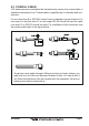
5.3 COAXIAL CABLE VHF antennas are connected to the transceiver by means of a coaxial cable, a shielded transmission line. Coaxial cable is specified by it’s diameter and construction. For runs less than 6 m, RG-58/U, about 6 mm in diameter is a good choice. For runs over 6 m but less than 15 m, the larger RG-8X should be used for cable runs over 15 m RG213 should be used. For installation of the connector onto the coaxial cable refer to the figure below.
6 INSTALLATION 6.1 LOCATION The radio can be mounted at any angle.
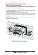
6.2.2 Optional MMB-84 Flush Mount Bracket 1. To assist in flush mounting, a template has been included. Use this template to assess the mounting location. 2. Use the template to mark the location where the rectangular hole is to be cut. Confirm the space behind the dash or panel is deep enough to accommodate the transceiver (at least 15 cm deep). There should be at least 1.5 cm between the transceiver’s heatsink and any wiring, cables or structures. 3.
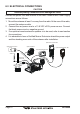
6.3 ELECTRICAL CONNECTIONS CAUTION Reverse polarity connections will damage the radio! Connect the power cord and antenna to the radio. Antenna and Power Supply connections are as follows: 1. Mount the antenna at least 1 m away from the radio. At the rear of the radio, connect the antenna cable. 2. Connect the red power wire to a 13.8 VDC ±20% power source. Connect the black power wire to a negative ground. 3. If an optional remote extension speaker is to be used, refer to next section for connections. 4.
6.
6.5 CHECKING GPS CONNECTIONS After connections have been made between the GX3000E and the GPS, a small satellite icon will appear on the top right corner of the LCD display. To see the additional GPS information, press and hold the [H/L(NAV)] key. The GX3000E shows the Date, Time, SOG and COG. 6.6 CHANGING THE GPS TIME From the Factory the GX3000E shows GPS satellite time or UTC time. A time offset is needed to show the local time in your area. 1.
6.7 CHANGING THE TIME LOCATION Sets the radio to show UTC time or local time with the offset inputted in section 7.5 Changing the GPS Time. 1. Press and hold down the [CALL(MENU)] key until “Radio Setup” menu appears. 2. Press the [ENT] key, then select “Time Disp” in the “Radio Setup ” menu with the CHANNEL selector knob. 3. Press the [ENT] key. 4. Turn the CHANNEL selector knob to select “UTC” or “Local.” 5. Press the [ENT] key to store the selected setting. 6.
6.8 CHANGING COG TO TRUE OR MAGNETIC Allows customising the NAV data showing GPS Course Over Ground (COG). Factory default is True however following the steps below the COG can be changed to Magnetic. 1. Press and hold down the [CALL(MENU)] key until “Radio Setup” menu appears. 2. Press the [ENT] key, then select “Magnetic” with the CHANNEL selector knob. 3. Press the [ENT] key. 4. Turn the CHANNEL selector knob to select “On” (representing “Magnetic”) or “Off” (representing “True”). 5.
6.9 RECEIVER AUDIO TONE CONTROL Allows the treble and bass of the speaker audio to be adjusted for the best acoustics in noisy environments. The effect is similar to adjusting the treble and bass controls on a stereo. 1. Press and hold down the [CALL(MENU)] key until “Radio Setup” menu appears. 2. Press the [ENT] key, then select “TONE CONT.” in the “Radio Setup” menu with the CHANNEL selector knob. 3. Press the [ENT] key, then select “BASS” with the CHANNEL selector knob. 4.
6.10 OPTIONAL ENHANCED RAM+ SECOND STATION MIC AND/OR VH-310 HANDSET INSTALLATION The GX3000E is capable of using up to 2 Enhanced RAM+ mics or VH-310 handsets to remotely control the Radio, DSC, and Distress functions. In addition the GX3000E can operate as a full function intercom system when either the RAM+ or VH-310 is connected. 1. Connect the Routing Cable to the one of the Remote Mic eight pin connectors on the rear panel, then tighten the Cable Nut (See Figure 2). 2.
Remote Mic or External Speaker Selection By default the RAM+ or VH-310 Handset internal speaker is turned on, however using the RAM+ mic (or VH-310 Handset) this speaker can be turned off so the external speaker can be used. RAM+ mic procedure 1. Press and hold the [CALL(ENT)] key. 2. Press the [S] or [T] key to select “RADIO SETUP.” 3. Press the [CALL(ENT)] key. 4. Press the [T] key to until “EXT SPK” is shown and press the [CALL(ENT)] key. 5.
7 CONTROLS AND INDICATORS NOTE This section defines each control of the transceiver. See Figures for location of controls. For detailed operating instructions refer to section “8 BASIC OPERATION.” POWER SWITCH / VOLUME CONTROL (VOL/PWR) Turns the transceiver on and off as well as adjusts the audio volume. Press and hold this knob for one second to turn the radio on. Clockwise rotation of this knob increases the audio volume level. Press and hold this knob for two seconds to turn the radio off.
KEYPAD [16/9] Key Immediately recalls channel 16 from any channel location and automatically selects high power. Pressing the [16/9] key again reverts to the previous selected working channel. Secondary use Press and hold the [16/9] key then press the [WX] key to switch between the USA, Canadian and International Channel Groups. [WX] Key Immediately recalls the previously selected NOAA weather channel from any channel.
[H/L(NAV)] Key Press this key to toggle the transmit output power between 25 W (High) and 1 W (Low) power. When the [H/L(NAV)] key is pressed while the transceiver is on channel 13 or 67, the power will temporarily switch from LO to HI power until the PTT is released. The [H/L(NAV)] key does not function on transmit inhibited and low power only channels. NOTE: 1W low power is indicated by LO on the display, when 25W high power is selected the display do not show an indication.
ANTENNA JACK Connects an antenna to the transceiver. Use a marine VHF antenna with an impedance of 50 ohms. REMOTE MIC CONNECTORS Connects the GX3000E to the enhanced RAM+ MIC (Remote Access Microphone) or the VH-310 Handset. Refer to section “11 ENHANCED RAM+ MIC OPERATION” or “12 VH-310 HEADSET OPERATION” for details. ACCESSORY CONNECTION CABLE Connects the GX3000E to a GPS, a PA speaker, and an external speaker. DC INPUT CABLE Connects the radio to a DC power supply capable of delivering 12V DC.
PTT (Push-To-Talk) SWITCH Keys the transmitter when the transceiver is in radio mode. If the transceiver is in the intercom mode (between the CMP25 RAM+ or VH-310 Headset and the GX3000E), or PA mode, it activates the GX3000E microphone for voice communications. MICROPHONE Transmits the voice message with reduction of background noise, using Clear Voice Noise Reduction Technology. NOTE: Be sure your mouth is about 1.5 cm from the mic hole for best performance.
MEMO GX3000E Page 23
8 BASIC OPERATION 8.1 RECEPTION 1. After the transceiver has been installed, ensure that the power supply and antenna are properly connected. 2. Press and hold the VOL/PWR knob until the radio turns on. 3. Turn the SQL knob fully counterclockwise. This state is known as “squelch off”. 4. Turn up the VOL knob until noise or audio from the speaker is at a comfortable level. 5. Turn the SQL knob clockwise until the random noise disappears. This state is known as the “squelch threshold.” 6.
8.4 SIMPLEX/DUPLEX CHANNEL USE Refer to the VHF MARINE CHANNEL CHART (page 91) for instructions on use of simplex and duplex channels. NOTE All channels are factory-programmed in accordance with International, Industry Canada (Canada), and FCC (USA) regulations. Mode of operation cannot be altered from simplex to duplex or vice-versa. 8.5 INTERNATIONAL, USA, AND CANADA MODE 1. To change the modes, hold the [16/9] key and press the [WX] key.
details). 3. The programmed NOAA weather channels will be scanned along with the regular-programmed channels. However, scanning will not stop on a normal weather broadcast unless a NOAA alert is received. 4. When an alert is received on a NOAA weather channel, scanning will stop and the transceiver will emit a loud beep to alert the user of a NOAA broadcast. 5. Press the [WX] key to stop the alert tone and receive the weather report.
8.8 CALLING ANOTHER VESSEL (CHANNEL 16 OR 9) Channel 16 may be used for initial contact (hailing) with another vessel. However, its most important use is for emergency and distress messages. This channel must be monitored at all times except when actually using another channel. It is monitored by the European, U.S. and Canadian Coast Guards and by other vessels. Use of channel 16 for hailing must be limited to initial contact only.
amples for USA use are Channels 24, 25, 26, 27, 28, 84, 85, 86, and 87. Call the marine operator and identify yourself by your vessel’s name, The marine operator will then ask you how you will pay for the call (telephone credit card, collect, etc.) and then link your radio transmission to the telephone lines. The marine telephone company managing the VHF channel you are using may charge a link-up fee in addition to the cost of the call. 8.
8.12 SCANNING Allows the user to select the scan type from Memory scan or Priority scan. “Memory scan” scans the channels that were programmed into memory. “Priority scan” scans the channels programmed in memory with the priority channel. 8.12.1 Selecting the Scan Type 1. Press and hold down the [CALL(MENU)] key until “Radio Setup” menu appears. 2. Press the [ENT] key, then select “SCAN Type” in the “Radio Setup ” menu with the CHANNEL selector knob. 3. Press the [ENT] key. 4.
8.12.3 Priority Scanning (P-SCAN) In the default setting, Channel 16 is set as the priority channel. You may change the priority channel to the desired channel from the Channel 16 by the Radio Setup Mode, refer to section “10.6 PRIORITY CHANNEL SET.” 1. Adjust the SQL knob until background noise disappears. 2. Select a desired channel to be scanned using the CHANNEL selector knob.
8.13 PA/FOG OPERATION PA/FOG mode allows the transceiver to be used as a 30W hailer when an optional STANDARD HORIZON 220SW or 240SW PA horn speaker is installed. When in Hail mode the PA speaker Listen’s Back (acts as a microphone and amplifies sound to the front panel speaker) through the PA horn speaker which provides two-way communications through the PA horn speaker.
switch to activate the tone through the HAIL/PA speaker. Rotate the CHANNEL selector knob to control the AF output level. The AF output level can be set from 0 to 30 watts. 6. To exit the FOG HORN mode, press the [PA/FOG] or [CLR] key. 8.14 NAVIGATION INDICATION The transceiver has the ability to display Time, SOG, COG, as well as the position (LAT/LON), when connected to a GPS receiver. 1. Press and hold the [H/L(NAV)] key, display the position information on the LCD.
8.15.1 Communication 1. Press and hold the [DW(IC)] key, the mode is changed to “INTERCOM” mode. 2. If your GX3000E is equipped with two CMP25 RAM+ Mic’s (or VH-310 Handset), select the companion you wish to communicate (Ram1, Ram2, or ALL) with the CHANNEL selector knob, then press the [ENT] key. 3. When the “INTERCOM” is activated, “Intercom ” is displayed on the GX3000E, and “IC” is displayed on the CMP25 RAM+ Mic or VH-310 Handset. 4. Press the PTT switch.
8.16 VOICE SCRAMBLER If privacy of communications is desired, a CVS2500 voice scrambler (VS) can be installed in the transceiver. Contact your Dealer to have a CVS2500 installed. Refer to the section 10.11 VOICE SCRAMBLER to program the voice scrambler. 1. Turn on the transceiver. 2. Select a channel that was programmed for scrambler mode (“VS” will appear on the LCD).
9 DIGITAL SELECTIVE CALLING 9.1 GENERAL WARNING This radio is designed to generate a digital maritime distress and safety call to facilitate search and rescue. To be effective as a safety device, this equipment must be used only within communication range of a shorebased VHF marine channel 70 distress and safety watch system. The range of signal may vary but under normal conditions should be approximately 20 nautical miles.
9.2.2 Programming the MMSI WARNING A user MMSI can be input only once. If the user tries to input an MMSI more than once the radio will show the display on the right. Therefore please be careful not to input the incorrect MMSI number. If the user needs to change the MMSI number after it has been entered, the radio will have to be returned to Factory Service. Refer to the section “14.2. FACTORY SERVICE.” 1. Press and hold down the [CALL(MENU)] key until Radio Setup the “Radio Setup” menu appears. 2.
9.3 DSC DISTRESS ALERT The GX3000E is capable of transmitting and receiving DSC Distress messages to all DSC radios. The GX3000E may be connected to a GPS to also transmit the Latitude and Longitude of the vessel. 10.3.1 Transmitting a DSC Distress Alert NOTE To be able to transmit a DSC Distress Alert an MMSI number must be programmed, refer to section “9.2.2 Programming the MMSI.” In order for your vessels location to be transmitted either connect a GPS to the GX3000E (refer to section “6.
Transmitting a DSC Distress Alert with Nature of Distress The GX3000E is capable of transmitting a DSC Distress Alert with the following “Nature of Distress” categories: Undesignated, Fire, Flooding, Collision, Grounding, Capsizing, Sinking, Adrift, Abandoning, Piracy, MOB 1. Lift the red spring loaded DISTRESS cover and press the [DISTRESS] key. The “DISTRESS” menu will appear on the LCD. 2. Turn the CHANNEL selector knob to select the desired nature of distress category. 3.
9.3.2 Receiving a DSC Distress Alert 1. When a DSC Distress Alert is received, an emergency alarm sounds. Then channel 16 is automatically selected. 2. Press any key to stop the alarm. 3. Turn the CHANNEL selector knob to change the display to show the position of the vessel in distress. 4 If the position of the vessel distress data does not include position, the LCD will show the display on the right. NOTE When there is an unread Distress Alert, the “DSC” icon will blink.
7. When “Manual” is selected at the previous step, enter the MMSI number (nine digits) to which you want to send (relay) the received Distress Alert. To do this, turn the CHANNEL selector knob to scroll through numbers “0-9,” the press the [ENT] key to move the entry location to the right. If a mistake was made entering in the MMSI number repeat pressing the [H/ L(NAV)] key until the wrong nunber is selected, then move the channel knob to correct the entry.
5. Press the [ENT] key to transmit the selected type of all ships DSC call. 6. After the ALL SHIPS CALL is transmitted, the transceiver will switch to CH16. 7. Listen to the channel to make sure it is not busy, then key the microphone and say PAN PAN PAN or “Securite, Securite, Securite” depending on the priority of the call. Say your call sign and announce the channel you wish to switch to for communications. 9.4.2 Receiving an All Ships Call 1.
9.5 INDIVIDUAL CALL This feature allows the GX3000E to contact another vessel with a DSC VHF radio and automatically switch the receiving radio to a desired communications channel. This feature is similar to calling a vessel on CH16 and requesting to go to another channel (switching to the channel is private between the two stations). 9.5.
Repeat this procedure until all nine spaces of the MMSI number are entered. 11. If a mistake was made entering in the name or the MMSI number repeat pressing the [H/L(NAV)] key until the wrong character is selected, then move the channel knob to correct the entry. 12. To store the data entered, press and hold the [ENT] key. 13. To enter another individual address, repeat steps 4 through 12. 14. To exit this menu and return to radio operation mode press the [16/9] key.
9.5.3 Setting up the Individual/Group Call Ringer When a Individual Call or Group Call is received the radio will produce a ringing tone for 3 minutes. This selection allows the Individual Call ringer time to be changed. 1. Press and hold down the [CALL(MENU)] key until Radio Setup “Radio Setup” menu appear. DSC 2. Turn the CHANNEL selector knob to select “DSC Setup Setup” menu. INDIV Ring 3. Press the [ENT] key, then select “INDIV Ring” with the CHANNEL selector knob. 4. Press the [ENT] key. 5.
9.5.4 Transmitting an Individual Call This feature allows the user to contact another vessel with a DSC radio. This feature is similar to calling a vessel on CH16 and requesting to go to another channel. Pre-Programmable Calling DSC Operation 1. Press the [CALL(MENU)] key. The “DSC Operation” menu will appear. Indi2. Turn the CHANNEL selector knob to select “Individual Exit vidual.” (To cancel, select “Exit Exit” with the CHANNEL selector knob or press the [16/9] key.) 3. Press the [ENT] key.
Manual Calling You may enter an MMSI number manually to contact without storing it in the Individual Directory. DSC Operation 1. Press the [CALL(MENU)] key. The “DSC Operation” menu will appear. Indi2. Turn the CHANNEL selector knob to select “Individual Exit vidual.” (To cancel, select “Exit Exit” with the CHANNEL selector knob or press the [16/9] key.) 3. Press the [ENT] key. The transceiver will beep, and the “Individual directory” will appear. 4.
13. Press any key to listen to the channel to make sure it is not busy, then key the microphone and call the other vessel you desire to communicate with. 9.5.5 Receiving an Individual Call When the GX3000E receives a individual call, by default the GX3000E automatically transmits a acknowledgement before switching to the requested channel. The GX3000E can be set so the GX3000E prompts you to manually send a reply, refer to section “9.5.2 Setting up Individual Reply.” 1.
9.6.2 Reviewing Received Calls Logged into the Call Waiting Directory 1. Press the [CALL(MENU)] key. The “DSC Operation” menu will appear. 2. Turn the CHANNEL selector knob to select “DSC Log” menu. 3. Press the [ENT] key, then turn the CHANNEL selector knob to select the category (“Distress” or “DSC Call”) you want to review and/or call back. 4. Press the [ENT] key, then turn the CHANNEL selector knob to select the station (name or MMIS number) you want to review and/or call back. 5.
9.7 GROUP CALL This feature allows the user to contact a group of specific vessels (example members of a yacht club) with a group MMSI number using the Group call function to automatically switch to a desired channel for voice communications. 9.7.1 Setting up a Group Call For this function to operate the same Group MMSI must be programmed into all the DSC VHF radios within the group of vessels that will be using this feature.
11. If a mistake was made entering in the name or the MMSI number repeat pressing the [H/L(NAV)] key until the wrong character is selected, then move the channel knob to correct the entry. 12. To store the data entered, press and hold the [ENT] key. 13. To enter another individual address, repeat steps 4 through 12. 14. To exit this menu and return to radio operation mode press the [16/9] key. 9.7.2 Transmitting a Group Call Pre-Programmable Calling 1. Press the [CALL(MENU)] key.
Manual Calling You may enter a Group MMSI number manually to contact without the Setting up the Group call number. 1. Press the [CALL(MENU)] key. The “DSC Operation” menu will appear. 2. Turn the CHANNEL selector knob to select “Group.” (To cancel, select “Exit” with the CHANNEL selector knob or press [16/9] key.) 3. Press the [ENT] key. The transceiver will beep, and the “Group Directory” will appear. 4. Turn the CHANNEL selector knob to select “Manual,” then press the [ENT] key. 5.
9.7.3 Receiving a Group Call 1. When a group call is received, the GX3000E will produce a ringing alarm sound. 2. The radio automatically switches to the requested channel. 3. Press any key to stop the alarm. 4. Monitor the channel for the person calling the Group for a message. 5. If you want to respond, monitor the channel to make sure it is clear, then press the PTT on the mic and talk to the calling ship(s). NOTE When there is an unread Group Call, the “DSC” icon will blink.
9.8 POSITION REQUEST Advancements in DSC have made it possible to poll the location of another vessel and show the position of that vessel on the display of the GX3000E. Standard Horizon has taken this feature one step further, if any Standard Horizon GPS is connected to the GX3000E, the polled position of the vessel is shown on the display of the GPS chart plotter making it easy to navigate to the location of the polled vessel.
The GX3000E has the capability to turn off the Position Request ringer. 1. Press and hold down the [CALL(MENU)] key until Radio Setup “Radio Setup” menu appears. DSC 2. Turn the CHANNEL selector knob to select “DSC Setup Setup” menu. DSC Beep Beep” with the 3. Press the [ENT] key, then select “DSC CHANNEL selector knob. 4. Press the [ENT] key. POS 5. Turn the CHANNEL selector knob to select “POS Request Request.” Off 6. Turn the CHANNEL selector knob to select “Off Off.” 7.
NOTE If the GX3000E does not receive position data from the polled vessel, the LCD will show “NO POSITION DATA.” Manual Request You may enter an MMSI number manually to contact without the Setting up the Individual / Position Call Directory. 1. Press the [CALL(MENU)] key. The “DSC Operation” menu will appear in the display. 2. Turn the CHANNEL selector knob to select “POS Request.” 3. Press [ENT] key to show the Position request directory. This directory uses the INDIVIDUAL Directory information. 4.
9.8.3 Receiving a Position Request When a position request call is received from another vessel, a ringing alarm will sound and POS REQUEST will be shown in the LCD. Operation and transceiver function differs depending on “POS Reply” in the “DSC Setup ” menu setting. Automatically reply: 1. When a position request call is received, a calling alarm sounds 4 times. Then requested position coordinates are transmitted automatically to the vessel requesting your vessels position. 2.
9.9 POSITION SEND The feature is similar to Position Request, however instead of requesting a position of another vessel this function allows you to send your position to another vessel. In order to send your position you need to have a GPS receiver connected or to have manually input your position. See “9.11 Manually Inputting Your GPS Location.” 9.9.1 Setting up a Position Send Ringer The GX3000E has the capability to turn off the Position Send ringer. 1.
Manual Calling 1. Press the [CALL(MENU)] key. The “DSC Operation” menu will appear in the display. 2. Turn the CHANNEL selector knob to select the “POS Send.” 3. Press [ENT] key to show the Position Send directory. This directory uses the INDIVIDUAL Directory information. 4. Turn the CHANNEL selector knob to select “Manual,” then press the [ENT] key. 5. Enter the MMSI number (nine digits) which you want to contact, then press the [ENT] key. 6.
9.10 DSC TRANSMISSION TEST DSC Operation 1. Press the [CALL(MENU)] key. The “DSC Operation” menu will appear. DSC Test 2. Turn the CHANNEL selector knob to select “DSC Test” menu. 3. Press the [ENT] key, then select the station (name or MMSI number) to be sent the test signal with the CHANNEL selector knob. 4. Press the [ENT] key. 5. Turn the CHANNEL selector knob to select the “Individual” you want to send the test signal or “Manual,” then press the [ENT] key. 6.
9.11 MANUAL INPUTTING GPS LOCATION (LAT/LON) You may send the Latitude/Longitude of your vessel manually even if the GX3000E is not connected the GPS receiver unit. After the position is entered, transmitting a DSC Distress, Position Request, or Position Send will contain the manually entered position. 1. Press and hold down the [CALL(MENU)] key until “Radio Setup” menu appears. 2. Turn the CHANNEL selector knob to select “DSC Setup” menu. 3.
10 RADIO SETUP NOTE The optional CMP25 RAM+ mic and VH-310 Handset can also change the RADIO SETUP menu. Refer to page 76 (RAM+ mic) and page 85 (VH-310) for details. 10.1 LAMP ADJUSTING Allows setting up the backlight intensity or to turn it off. 1. Press and hold down the [CALL(MENU)] key until “Radio Setup” menu appears. 2. Press the [ENT] key, then select “Dimmer ” in the “Radio Setup ” menu with the CHANNEL selector knob. 3. Press the [ENT] key. 4.
10.3 TIME OFFSET From the Factory the GX3000E shows GPS satellite time or UTC time. A time offset is needed to show the local time in your area. 1. Press and hold down the [CALL(MENU)] key until “Radio Setup” menu appears. 2. Press the [ENT] key, then select “Time Set ” in the “Radio Setup ” menu with the CHANNEL selector knob. 3. Press the [ENT] key. 4. Turn the CHANNEL selector knob to select time offset from UTC. See illustration below to find your offset time from UTC.
10.4 TIME LOCATION This selection selects the time display between local time and UTC (time GPS sends to radio). Time is displayed when GPS position (LAT/LON) is displayed by pressing and holding the [H/L(NAV)] key. 1. Press and hold down the [CALL(MENU)] key until “Radio Setup” menu appears. 2. Press the [ENT] key, then select “Time Disp.” in the “Radio Setup ” menu with the CHANNEL selector knob. 3. Press the [ENT] key. 4. Turn the CHANNEL selector knob to select “UTC” or “Local.” 5.
10.6 PRIORITY CHANNEL SET Allows selection of the priority channel when priority scan is enabled. 1. Press and hold down the [CALL(MENU)] key until “Radio Setup” menu appears. 2. Press the [ENT] key, then select “Priority CH” in the “Radio Setup ” menu with the CHANNEL selector knob. 3. Press the [ENT] key. 4. Turn the CHANNEL selector knob to select the channel to be a priority. 5. Press the [ENT] key to store the selected setting. 6.
10.8 SCAN RESUME TIME This selection is used to select the time the GX3000E waits after a transmission ends before starting scanning. 1. Press and hold down the [CALL(MENU)] key until “Radio Setup” menu appears. 2. Press the [ENT] key, then select “SCAN Resume” in the “Radio Setup” menu with the CHANNEL selector knob. 3. Press the [ENT] key. 4. Turn the CHANNEL selector knob to select the desired resume time. The resume time can be set to “1sec,” “2sec,” “3sec,” or “Off .
10.10 WX ALERT This selection allows the radios NOAA Weather alert to be turned off. Default setting is ON. 1. Press and hold down the [CALL(MENU)] key until “Radio Setup” menu appears. 2. Press the [ENT] key, then select “WX Alert” in the “Radio Setup ” menu with the CHANNEL selector knob. 3. Press the [ENT] key. 4. Turn the CHANNEL selector knob to select the desired WX alert mode. The WX alert mode can be set WX,” or “Off.” to “On SCAN,” “On WX,” “On SCAN SCAN/WX [ ] 5.
10.12 CHANNEL NAME CHANGE This selection allows you to customise the name of a channel from the default name. 1. Press and hold down the [CALL(MENU)] key until “Radio Setup” menu appears. 2. Press the [ENT] key, then select “CH Name” in the “Radio Setup ” menu with the CHANNEL selector knob. 3. Press the [ENT] key. 4. Turn the CHANNEL selector knob to select the channel to be named, then press the [ENT] key. 5. Turn the CHANNEL selector knob to scroll through the first letter of the channel name. 6.
10.13 NAMING THE RADIO OR SECOND STATION MIC OR HANDSET This function allows you to change the name of the RADIO or second station microphones. Example: “RADIO - CABIN,” “RAM1 - HELM,” “RAM2 FLYBRIDGE.” 1. Press and hold down the [CALL(MENU)] key until “Radio Setup” menu appears. 2. Press the [ENT] key, then select “Unit Name” in the “Radio Setup ” menu with the CHANNEL selector knob. 3. Press the [ENT] key. 4.
10.14 FOG ALERT TONE FREQUENCY This selection allows you to select the Alert Tone Frequency for the PA/FOG Operation. Available selections are “200 Hz” through “850 Hz” in 50 Hz steps. The default Alert Tone Frequency is 400 Hz. 1. Press and hold down the [CALL(MENU)] key until “Radio Setup” menu appears. 2. Press the [ENT] key, then select “FOG Freq.” in the “Radio Setup ” menu with the CHANNEL selector knob. 3. Press the [ENT] key. 4. Turn the CHANNEL selector knob to select desired tone frequency. 5.
11 ENHANCED RAM+ MIC OPERATION When the RAM+ microphone is connected to the GX3000E, most VHF, DSC, and setup menus can be remotely operated. The RAM+ Mic is supplied with 7 m of routing cable and can be extended up to 21 m using three 7 m extension cables model CT-100. The intercom operation can be used between the RAM+ Mic and the transceiver. 11.1 RAM+ MIC CONTROLS ENT MENU NAV DW IC WX U.I.C CLR 16 9 SQUELCH CONTROL (SQL) Activates the squelch adjusting mode.
POWER SWITCH (PWR) Press and hold down this key to turn to the transceiver and RAM+ Mic on and off. PTT (Push-To-Talk) SWITCH Activates transmission. [H/L] KEY Toggles between high and low power. When the [H/L] key is pressed while the transceiver is on channel 13 or 67, the power will temporarily switch from LO to HI power until the PTT is released. The [H/L] key does not function on transmit inhibited and low power only channels.
[DW(IC)] Key Watches for a transmission on CH16 and another selected channel until either signal is received. (Dual watch) Secondary use Press and hold [DW(IC)] key, intercom operation will operate between radio and RAM+ Mic. [NAV] Key Press this key, when connected to the GPS receiver, the LCD displays Position Data and Time from the GPS. Secondary use Press and hold [NAV] key, activate the PA/FOG mode. [WX] Key Immediately recalls the previously selected US NOAA weather channel from any channel location.
11.2 PA/FOG OPERATION The RAM+ is capable of controlling the 30W Public address, 4 fog horns, bells and whistles. 11.2.1 Operating the PA / Hailer 1. Press and hold the [NAV] key then select “PUBLIC ADRESS” with the [S] or [T] key. 2. Press the [CALL(ENT)] key. 3. Press the PTT switch and speak into the microphone. 4. To turn up the PA Volume, press the PTT switch and press the [S ] or [T ] keys to adjust the Audio output level. The level can be set from 0 to 30W. 5.
11.3 INTERCOM OPERATION 11.3.1 Communication 1. Press and hold the [DW(IC)] key while in “RADIO” mode, the mode is changed to “INTERCOM” mode. 2. If your GX3000E is equipped with two RAM+ Mic’s (or VH310 Handset), select the companion with which you wish to communicate (RADIO, RAM, or ALL) with the [S] or [T] keys, then press the [CALL(ENT)] key. 3. When the “INTERCOM” operation is activated, “IC” is displayed on the RAM+ Mic (and VH-310 Handset) and “INTERCOM” is displayed on the GX3000E. 4.
11.4 MANUAL INPUTTING OF THE GPS LOCATION (LAT/LON) You may send the Latitude/Longitude of your vessel manually from the RAM+ Mic even if the GX3000E is not connected the GPS receiver unit. After the position is entered, transmitting a DSC Distress, Position Request, or Position Send will contain the manually entered position. 1. Press and hold down the [CALL(ENT)] key until “Radio Setup” menu appears. 2. Press the [T] key to select “DSC SETUP” menu. 3.
11.5 DSC/RADIO SETUP MODE The RAM+ can access the DSC / RADIO setup menu (refer to section “9 DIGITAL SELECTIVE CALLING” and section “10 RADIO SETUP MODE” for details). The LAMP, CONTRAST, and KEY BEEP menu item accessed from the RAM+ only controls the RAM+’s display and speaker. DSC/RADIO Setup mode from the RAM+: 1. Press and hold down the [CALL(ENT)] key until “RADIO SETUP” menu appears. 2. Press the [S]/[T] key to select “RADIO SETUP” or “DSC SETUP” menu. 3.
11.5.1 Changing GPS Information to Vessel Position or COG Allows customising of the NAV data showing GPS Information. Factory default is “Your Vessel’s Current Position,” however, following the steps below the GPS Information can be changed to “Course Over Ground (COG).” 1. Press and hold down the [CALL(ENT)] key until “RADIO SETUP” menu appears. 2. Press the [CALL(ENT)] key, then select “NAV DISPLAY” with the [S]/[T] key. 3. Press the [CALL(ENT)] key. 4.
12 VH-310 HANDSET OPERATION When the VH-310 HANDSET is connected to the GX3000E, most VHF, DSC, and setup menus can be remotely operated. The VH-310 HANDSET is supplied with 7 m of routing cable and can be extended up to 21 m using three 7 m extension cables model CT-100. The intercom operation can be used between the VH-310 HANDSET or the GX3000E. 12.1 VH-310 HANDSET CONTROLS PWR key Press and hold down this key to turn to the transceiver and VH-310 HANDSET on and off.
[SQL] key Activates the squelch adjusting mode. Press this key to activate the squelch adjusting mode. Press the [S] or [T] key to adjust the squelch. [CALL(MENU)] key The [CALL(MENU)] key functions as the enter key. Secondary use Press the [CALL(MENU)] key to access the DSC OPERATION menu. The “INDIVIDUAL CALL,” “GROUP CALL,” “ALL SHIP CALL,” “POSITION REQUEST,” POSITION SEND,” STANDBY MODE,” and “CALL WAITING” functions can be accessed from the DSC OPERATION menu.
KEYPAD [1(DIM)] key When in radio mode, this key is used to directly select digit “1” in a channel number. Secondary use Press the [F] key first then press the [1(DIM)] key to access the LCD Dimmer menu. Refer to section “10.1 LAMP ADJUSTING” for details. [2(MEM)] Key When in radio mode, this key is used to directly select digit “2” in a channel number. Secondary use Press the [F] key first then press the [2(MEM)] key, memorise the selected channel into the transceiver scan memory for scanning.
[6(NAV)] Key When in radio mode, this key is used to directly select digit “6” in a channel number. Secondary use Press the [F] key first then press the [6(NAV)] key, the LCD will display NAV GPS Data, Time, SOG (Speed Over Ground), and COG (Course Over Ground) when a GPS is connected to the accessory cable of the GX3000E. See section “6.3 ACCESSORY CABLE” for details. [7(SCRM)] Key When in radio mode, this key is used to directly select digit “7” in a channel number.
12.2 PA/FOG OPERATION The VH-310 Handset is capable of controlling the 30W Public address, 4 fog horns, bells and whistles. 12.2.1 Operating the PA / Hailer 1. Press the [F] key followed by the [8(PA)] key, activate the “PA / HAIL” mode. 2. Press the PTT switch and speak into the microphone. 3. To turn up the PA Volume, press the PTT switch and press the [S ] or [T ] keys to adjust the Audio output level. The level can be set from 0 to 30W. 4.
12.3 INTERCOM OPERATION 12.3.1 Communication 1. Press the [F] key followed by the [5(IC)] key, the mode is changed to “INTERCOM” mode. 2. If your GX3000E is equipped with two RAM+ Mic’s (or VH310 Handset), select the companion you wish to communicate (RADIO, RAM, or ALL) with the [S] or [T] keys, then press the [ENT] key. 3. When the “INTERCOM” operation is activated, “IC” is displayed on the VH-310 Handset (and RAM+ Mic, if used) and “INTERCOM” is displayed on the GX3000E. 4.
12.4 MANUAL INPUTTING OF THE GPS LOCATION (LAT/LON) You may send the Latitude/Longitude of your vessel manually from the VH-310 Handset even if the GX3000E is not connected the GPS receiver unit. After the position is entered, transmitting a DSC Distress, Position Request, or Position Send will contain the manually entered position. 1. Press and hold down the [CALL(MENU)] key until “Radio Setup” menu appears. 2. Press the [T] key to select “DSC SETUP” menu. 3.
12.5 DSC/RADIO SETUP MODE The VH-310 Handset can access the DSC / RADIO setup menu (refer to section “9 DIGITAL SELECTIVE CALLING” and section “10 RADIO SETUP MODE” for details). The CONTRAST, NAV DISPLAY, KEY BEEP, and AF SELECT menu item accessed from the VH-310 Handset only controls the VH-310 Handset’s display and speaker. DSC/RADIO Setup mode from the VH-310 Handset: 1. Press and hold down the [CALL(MENU)] key until “RADIO SETUP” menu appears. 2.
12.5.1 Changing GPS Information to Vessel position or COG Allows customising of the NAV data showing GPS Information. Factory default is “Your Vessel’s Current Position,” however, following the steps below the GPS Information can be changed to “Course Over Ground (COG).” 1. Press and hold down the [CALL(MENU)] key until “RADIO SETUP” menu appears. 2. Press the [ENT] key, then select “NAV DISPLAY” with the [S]/[T] key. 3. Press the [ENT] key. 4.
13 FOG HORN TIMING CHART The fog horn function sounds a horn repeatedly until the function is turned off. TYPE UNDERWAY PATTERN One 5-second blasts every 120 seconds. USAGE Motor vessel underway and making way. Listen Back 120s STOP Two 5-second blasts (separated by 2 seconds) every 120 seconds. 5s Motor vessel underway but stopped (not making way). 5s Li sten B ack 2s 2s 120s SAIL One 5-second blasts followed by two 1second blasts (separated by 2 seconds) every 120 seconds.
14 MAINTENANCE The inherent quality of the solid-state components used in this transceiver will provide many years of continuous use. Taking the following precautions however, will prevent damage to the transceiver. • • • • Keep the microphone connected or the jack covered at all times to prevent corrosion of electrical contacts; Never key the microphone unless an antenna or suitable dummy load is connected to the transceiver.
14.3 TROUBLESHOOTING CHART SYMPTOM PROBABLE CAUSE REMEDY Transceiver fails to power up. No DC voltage to the a. Check the 12VDC battery connections and transceiver, or blown the fuse. fuse. b. The PWR key needs to be pressed and held to turn the radio on. Transceiver blows fuse when connected to power supply. Reversed power wires. Check the power cable for DC voltage, or replace the fuse (6A 250V).
15 CHANNEL ASSIGNMENTS Tables on the following columns list the VHF Marine Channel assignments for U.S.A. and International use. Below are listed some data about the charts. 1. VTS. Where indicated, these channels are part of the U.S. Coast Guard’s Vessel Traffic System. 2. Alpha channel numbers, that is, channel numbers followed by the letter A (such as Channel 07A) are simplex channels on the U.S.A. or Canadian channel assignments whose counterparts in the International assignments are duplex channels.
6. Marine vessels equipped with VHF radios are required to monitor Channel 16. CH 01 01A 02 03 03A 04 U C X X X X X 04A X 05 05A 06 07 X X X X 07A 08 09 X X X X X X 10 11 12 13 14 15 15 16 17 18 18A 19 19A 19A 20 X X X X X X X X X X X 20A 21 21A 22 22A X X X X X X X X X X X X X X X X GX3000E VHF MARINE CHANNEL CHART I S/D TX RX CHANNEL USE X D 156.050 160.650 Public Correspondence (Marine Operator) S 156.050 Port Operation and Commercial. VTS in selected areas X D 156.100 160.
CH 23 23A 24 25 26 27 28 60 61 U 61A X X X X X X X C X X X X X X X X 62 62A X 63 63A X 64 64A X X X 65A 66 X X 66A 67 X X X X 68 69 X X X X 70 X X 71 X X 72 73 X X X X 74 X X 65 Page 92 VHF MARINE CHANNEL CHART I S/D TX RX CHANNEL USE X D 157.150 161.750 Public Correspondence (Marine Operator) S 157.150 U.S. Government Only X D 157.200 161.800 Public Correspondence (Marine Operator) X D 157.250 161.850 Public Correspondence (Marine Operator) X D 157.300 161.
CH 75 76 77 77 78 U X X X C 78A 79 79A 80 80A 81 81A X X X X X X X X 82A X X 83 83A X X X 83 84 85 86 87 88 88A WX01 WX02 WX03 WX04 WX05 WX06 WX07 WX08 WX09 WX10 X X X X X X X X X X X X X X X X X 82 X X X X X X X X X X X X X X X X VHF MARINE CHANNEL CHART S/D TX RX CHANNEL USE S 156.775 Port Operations (Inter-ship only) (1W) S 156.825 Port Operations (Inter-ship only) (1W) S 156.875 Port Operations (Inter-ship only) (1W) X S 156.875 Port Operations (Inter-ship only) X D 156.925 161.
16 SPECIFICATIONS Performance specifications are nominal, unless otherwise indicated, and are subject to change without notice. 16.1 GENERAL Channels ............................................................. All USA, International and Canadian Input Voltage ....................................................................................... 13.8 VDC ±20% Current Drain Standby ........................................................................................................... 0.5 A Receive ....
Declaration of Conformity We, Yaesu Europe B.V. declare under our sole responsibility that the following equipment complies with the essential requirements of the Directive 1999/5/EC. Type of Equipment: Brand Name: Model Number: Manufacturer: Address of Manufacturer: VHF Transceiver STANDARD HORIZON GX3000E Vertex Standard Co., Ltd.
VERTEX STANDARD CO., LTD. 4-8-8 Nakameguro, Meguro-Ku, Tokyo 153-8644, Japan VERTEX STANDARD US Headquarters 10900 Walker Street, Cypress, CA 90630, U.S.A. YAESU EUROPE B.V. P.O. Box 75525, 1118 ZN Schiphol, The Netherlands YAESU UK LTD. Unit 12, Sun Valley Business Park, Winnall Close Winchester, Hampshire, SO23 0LB, U.K. Copyright 2006 VERTEX STANDARD CO., LTD. All rights reserved. No portion of this manual may be reproduced without the permission of VERTEX STANDARD CO., LTD.