Horizon HX350S VHF/FM Marine Handheld Transceiver Owner’s Manual HX350S LA MP SC AN WX H/ 16/9 ME M A/B L LE SIB ER BM SU HX350S Owner’s Manual page 23
TABLE OF CONTENTS GENERAL INFORMATION .................................................................................... 1 INTRODUCTION .................................................................................................... 1 FCC/ INDUSTRY CANADA INFORMATION .......................................................... 1 ACCESSORIES ...................................................................................................... 2 PACKING LIST ...............................................
1 GENERAL INFORMATION 1.1 INTRODUCTION The Standard Communications Corp. (SCC) HX350S is a marine handheld two-way VHF transceiver. The transceiver has 65 channels: 55 marine and 10 weather. The 55 marine channels are switchable to comply with either USA, International, or Canadian regulations. It has an emergency channel 16 which can be immediately selected from any channel by pressing the red 16/9 key. Weather channels can also be accessed immediately by pressing the WX key.
2 ACCESSORIES 2.1 PACKING LIST When the package containing the transceiver is first opened, please check it for the following contents: • HX350S Transceiver • CBT350 Alkaline Battery Tray • CAW240 DC Charge Cable with 12 V Cigarette Lighter • CNB350/CNB350AS Rechargeable Battery Pack • CCA250 Charge Adaptor with screws • CWC230 120VAC Wall Charger for CCA250 • CAT350 Flexible Antenna with STUD connector • Lanyard • Belt Clip with screws • Owner’s Manual • Owner’s Manual Supplement 2.2 OPTIONS CMP350 ....
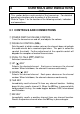
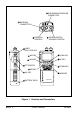
3 CONTROLS AND INDICATORS NOTE This section defines each control of the transceiver. For detailed operating instructions refer to section 4 of this manual. Refer to Figure 1 for the location of the following controls, indicators, and connections. 3.1 CONTROLS AND CONNECTIONS q POWER SWITCH/VOLUME CONTROL Turns the transceiver on and off, and adjusts the volume. w SQUELCH CONTROL (SQL) Sets the point at which random noise on the channel does not activate the audio circuits but a received signal does.
SPEAKER/MICROPHONE CONNECTOR ANTENNA CONNECTOR SQL VOL OFF POWER SWITCH VOLUME CONTROL SQUELCH CONTROL LAMP/ KEY LOCK KEY WX KEY 16/9 KEY HX350S LAMP SCAN KEY UP KEY WX SCAN A/B MEM 16/9 H/L PTT SWITCH DOWN KEY A/B KEY H/L KEY MEM KEY BATTERY PACK SUBMERSIBLE Figure 1.
i SCAN KEY Starts scanning programmed channels. Press this key for at least 1 second to turn on and off priority scan (scanning of programmed channels and priority channel) during scan. o MEM (Scrambler) KEY Memorizes the selected channel. When pressed again, deletes the memorized channel. Hold down this key for at least 1 second, to turn the scrambler on and off. (if an optional CVS240 voice scrambler is installed) !0 A/B KEY Immediately recalls two user assigned channels from any channel.
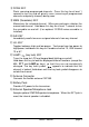
3.2 INDICATORS T X DISTRESS CALLING U S A CAN WX INTL MEM S H L Figure 2. Indicators Channel Display The operating channel in both transmission and reception mode. A Indicator Ship-ship channel in USA or Canadian mode whose counterpart in the International mode is a public corespondence (marine operator) channel. USA/INTL/CAN Indicator The modes of operation for the particular channel. “USA” indicates USA mode. “INTL” indicates International mode and “CAN” indicates Canadian mode.
Battery Indicator Battery life, during transmission and reception, is as follows: : Over 50% charged : 25% charged : Less than 10% charged : Need to charge (Also see Section 5.1) NOTE The battey life indicator is accessed immediately by pressing the PTT switch. The battery indicator should be used only as a guide in charging the CNB350/CNB350AS battery. S Indicator ” on the display The small character “ S ” above the keylock symbol “ indicates the scrambler code.
4 OPERATION 4.1 INITIAL PROCEDURE NOTE Never key the transceiver without an antenna connected. Damage may occur to the transceiver. Do not operate the transceiver while charging. 1. Install the belt clip on the transceiver if desired. Use the 2 Phillips-head screws included with the clip to mount the clip to the back of the transceiver. 2. Install the nylon carrying strap on the belt clip if desired. 3. Install the battery pack on the transceiver. (see figure 4 and section 5.2) 4.
6. To change channels, press the or key. Sometimes, a slight adjustment of the squelch threshold is needed as some channels have a higher noise level than others. Please refer to the Owner’s Manual Supplement for a complete listing of all USA, International and Canadian VHF Marine channels and their use. 7. If necessary, press the LAMP/ key to turn on the lamp. The lamp automatically turns off in about 5 seconds. To turn off the lamp sooner, press the LAMP/ key again. 8.
4.4 TRANSMIT TIME - OUT TIMER (TOT) While the PTT switch is held down, transmission time is limited to 5 minutes. This prevents prolonged unintentional transmissions. About 10 seconds before automatic transmitter shutdown, a warning beep is sounded from the speaker. The transceiver automatically switches to the receiving mode, even if the PTT switch is held down. Before transmitting again, the PTT switch must first be released and pressed again.
4.7 SCAN 1. Select the desired channel to be scanned using the or key. 2. Press the MEM key to store the channel into the transceiver's memory. “MEM” is displayed on the LCD. 3. Repeat steps 1 and 2 for all the channels to be scanned. 4. To delete a channel from the transceiver’s scan memory, press the MEM key again while the memorized channel is displayed. “MEM” disappears. 5. All channels programmed remain in the transceiver’s scan memory even if the power is turned off. See section “4.
4.9 WEATHER ALERT In the event of extreme weather disturbances such as storms and hurricanes, NOAA (National Oceanic and Atmospheric Administration) sends a weather alert accompanied by a 1050 Hz tone and subsequent weather reports on the weather channels. The transceiver is capable of receiving this alert if the following is performed: 1. Program weather channels into the transceiver’s memory for scanning. Follow the same procedure as for regular channels under Section 4.7. 2.
4.13 OPERATING ON CHANNEL 67 When channel 67 is used for navigational bridge-to-bridge traffic between ships, high power may be used temporarily in the USA mode by pressing the H/L key. When the H/L key is released, the transceiver will revert low power. 4.14 CHANNEL A/B INSTANT ACCESS Two user-assigned channels can be programmed for instant access. USA channels 9 and 16, and WX channels should not be assigned as A or B channels because they are readily available with the 16/9 and WX keys.
4.14.2 Operation Pressing the A/B key more than once toggles between channel A and channel B. Channel A is represented by “A” to the left of the channel number on the LCD, and channel B is represented by “b”. Do not confuse this “A” with the one that sometimes is displayed to the right of the channel number (described in the section 3.2 of this Owner’s Manual). 4.15 SIMPLEX/DUPLEX CHANNEL USE All channels are factory-programmed in accordance with FCC(USA), Industry Canada and International regulations.
3. Press the MEM key to store the scrambler code in the transceiver's memory. The display shows: TX USA CAN INTL S or key to set the scrambled channel (scrambled 4. Press the channel = CH05). The display shows: TX USA CAN INTL S 5. Press the MEM key to store the scrambled channel in the transceiver. “MEM” will be displayed on LCD. TX MEM USA CAN INTL S 6. To program other channels to be scrambled, repeat steps 4 and 5. Only one scrambler code can be chosen for all channels programmed. 4.16.
4.17 RESETTING THE TRANSCEIVER’S MICROPROCESSOR Resetting the microprocessor restores the initial, factory supplied conditions in the transceiver. These are called the default conditions. To reset the microprocessor, first turn the transceiver off. Then while holding the WX and SCAN keys pressed, turn the transceiver on. The default conditions are: • No channel numbers are in memory. • Channel 16 is the priority channel. • Channel 16 will be selected when the transceiver is turned on.
5 BATTERY CAUTION To avoid risk of explosion and injury, CNB350/CNB350AS battery pack should only be removed, charged or recharged in non-hazardous environments. 5.1 BATTERY CHARGING To check the charge status, install the battery and press the PTT switch while observing the BATT indicator. (see page 7) The battery charge system (CCA250 and CWC230) supplied with the transceiver recharges a completely discharged CNB350/CNB350AS battery pack in about 15 hours.
5.3 OPERATING BATTERY CHARGE SYSTEM 1. Plug the end of CWC230 wall charger to the DC IN connector of the CCA250 charge adaptor. 2. Plug the wall charger into a 120 VAC wall outlet. 3. Turn the transceiver off. 4. Insert the transceiver. The indicator lights, and charging begins. 5. Remove the battery pack from charge adaptor when charging time has passed. NOTE The CWC230 can be replaced by the CAW240 mobile cable, or CWC232 120/230 VAC wall charger.
5.5 BATTERY SAFETY Battery packs for your transceiver contain Nickel-cadmium (Ni-Cd) batteries. This type of battery stores a charge powerful enough to be dangerous if misused or abused, especially when removed from the transceiver. Please observe the following precautions: DO NOT SHORT BATTERY PACK TERMINALS Shorting the terminals that power to the transceiver can cause sparks, severe overheating, burns, and battery cell damage.
6 MAINTENANCE For preventive maintenance and instructions on obtaining factory service, please refer to the OWNER’S MANUAL SUPPLEMENT. For general troubleshooting, refer to this Troubleshooting Chart. TROUBLESHOOTING CHART SYMPTOM PROBABLE CAUSE REMEDY The SCAN key does not start the scan. No channels memorized. Use the MEM key to enter desired channels into the transceiver’s memory. Squelch is not adjusted. Adjust the squelch to threshold or to the point where noise just disappears.
7 SPECIFICATIONS Performance specifications are nominal, unless otherwise indicated, and are subject to change without notice. 7.1 GENERAL Frequency Range ............................................... 156.025 to 163.275 MHz Channels ................................. All currently allocated USA, Canadian and International channels, plus 10 weather channels. RF Power Output with CNB350/CNB350AS Battery ........ 5.0 W (high) 1.0 W (low) Operating Voltage ...................................................
Standard Communication Corp. P.O. Box 92151 Los Angeles, CA 90009-2151 Telephone 310/532-5300 © STANDARD COMMUNICATIONS CORP.