
Operation Manual
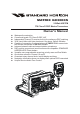


GX3000SPage 10
8 INSTALLATION
8.1 LOCATION
The radio can be mounted at any angle. Choose a mounting location that:
• is far enough from any compass to avoid any deviation in compass read-
ing due to the speaker magnet
• provides accessibility to the front panel controls
• allows connection to a power source and an antenna
• has nearby space for installation of a microphone hanger
• the antenna must be mounted at least 3 feet from radio
Note: To insure the radio does not affect the compass or radios performance is
not affected by the antenna location, temporarily connect the radio in the de-
sired location and:
a. Examine the compass to see if the radio causes any deviation
b. Connect the antenna and key the radio. Check to ensure the radio is
operating correctly by requesting a radio check.
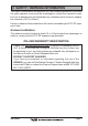
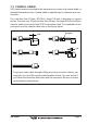
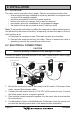
8.2 ELECTRICAL CONNECTIONS
CAUTION
Reverse polarity connections will damage the radio!
Connect the power cord and antenna to the radio. Antenna and Power Supply
connections are as follows:
1. Mount the antenna at least 3 feet away from the radio. At the rear of the
radio, connect the antenna cable.
2. Connect the red power wire to a 13.8 VDC ±20% power source. Connect
the black power wire to a negative ground.
3. If an optional remote extension speaker is to be used, refer to next section
for connections.
4. It is advisable to have a Certified Marine Technician check the power out-
put and the standing wave ratio of the antenna after installation.
GPS Navigation Receiver
A
c
c
e
s
s
o
r
y
C
a
b
l
e
Optional Speaker
Antenna
Fuse
Red
Power Source
Black
Water proof
Deck Outlet
Optional CMP25 RAM+ Mic.
Optional VH-310 Handset
Optional HAIL/PA Horn