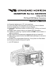
QUANTUM Series GX3500S 25 Watt VHF/FM ITU Class D DSC Marine Transceiver Owner's Manual Oversized alphanumeric LCD, knobs and keys 30 W Loud Hailer with listen back and 4 fog horns, Bells & Whistles Direct keypad entry of a channel using the keypad Removable ClearVoice speaker microphone with 16/9 key and channel selection Display shows channel names, and repeats GPS information8 Capable of connecting 2 optional enhanced RAM+ second station remote microphones DSC distress call automati
TABLE OF CONTENTS 1 2 3 4 5 6 7 GENERAL INFORMATION ...................................................................................... 4 PACKING LIST ........................................................................................................ 4 OPTIONS ................................................................................................................. 4 SAFETY / WARNING INFORMATION ......................................................................
TABLE OF CONTENTS 12 13 14 15 16 17 18 11.3 DSC DISTRESS CALL ................................................................................. 38 11.3.1 Tansmitting a DSC Distress Call ........................................................ 38 11.3.2 Receiving a DSC Distress Call .......................................................... 40 11.4 ALL SHIPS CALL ......................................................................................... 40 11.4.1 Transmitting an All Ships Call ...........
1 GENERAL INFORMATION The Vertex Standard GX3500S is a VHF/FM transceiver designed for use in the frequency range of 156.025 to 163.275 MHz. The GX3500S can be operated from 11 to 16 VDC and has a switchable RF output power of 1 watt or 25 watts. The GX3500S is capable of DSC (Digital Selective Calling) Class D operation and an Enhanced second station RAM+ mic (CMP25 remote-control speaker/ microphone with display).
4 SAFETY / WARNING INFORMATION This radio is restricted to occupational use, work related operations only where the radio operator must have the knowledge to control the exposure conditions of its passengers and bystanders by maintaining the minimum separation distance of 0.6 m (2 feet). Failure to observe these restrictions will result in exceeding the FCC RF exposure limits. Antenna Installation: The antenna must be located at least 0.
5 FCC RADIO LICENSE INFORMATION Vertex Standard radios comply with the Federal Communication Commission (FCC) requirements that regulate the Maritime Radio Service. STATION LICENSE An FCC ship station license is no longer required for any vessel traveling in U.S. waters (except Hawaii) which is under 20 meters in length.
6 FCC NOTICE NOTICE Unauthorized changes or modifications to this equipment may void compliance with FCC Rules. Any change or modification must be approved in writing by Marine Division of Vertex Standard. NOTICE This equipment has been tested and found to comply with the limits for a Class B digital device, pursuant to Part 15 of the FCC Rules. These limits are designed to provide reasonable protection against harmful interference in a residential installation.
7 GETTING STARTED 7.1 ABOUT VHF RADIO The radio frequencies used in the VHF marine band lie between 156 and 158 MHz with some shore stations available between 161 and 163 MHz. The marine VHF band provides communications over distances that are essentially “line of sight” (VHF signals do not travel well through objects such as buildings, hills or trees). Actual transmission range depends much more on antenna type, gain and height than on the power output of the transmitter.
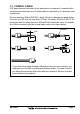
7.3 COAXIAL CABLE VHF antennas are connected to the transceiver by means of a coaxial cable – a shielded transmission line. Coaxial cable is specified by it’s diameter and construction. For runs less than 20 feet, RG-58/U, about 1/4 inch in diameter is a good choice. For runs over 20 feet but less than 50 feet, the larger RG-8X or RG-213/U should be used for cable runs over 50 feet RG-8X should be used. For installation of the connector onto the coaxial cable refer to the figure below.
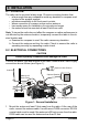
8 INSTALLATION 8.1 LOCATION The radio can be mounted at any angle.
2. Connect the red power wire to a 13.8 VDC ±20% power source. Connect the black power wire to a negative ground. 3. If an optional remote extension speaker is to be used, refer to next section for connections. 4. It is advisable to have a Certified Marine Technician check the power output and the standing wave ratio of the antenna after installation. 8.
8.
8.6 CHANGING THE GPS TIME From the Factory the GX3500S shows GPS satellite time or UTC time. A time offset is needed to show the local time in your area. 1. Press and hold down the [CALL(MENU)] key until “Radio Setup” menu appears. 2. Press the [ENT] key, then select “Time Set” with the CHANNEL selector knob. 3. Press the [ENT] key. 4. Turn the CHANNEL selector knob to select time offset from UTC. See illustration below to find your offset time from UTC.
8.7 CHANGING THE TIME LOCATION You may select the time display between local time and UTC (time GPS sends to radio). Time is displayed when GPS position (LAT/LON) is displayed by pressing the [F] key followed by the [6(NAV)] key. 1. Press and hold down the [CALL(MENU)] key until “Radio Setup” menu appears. 2. Press the [ENT] key, then select “Time Disp” in the “Radio Setup” menu with the CHANNEL selector knob. 3. Press the [ENT] key. 4. Turn the CHANNEL selector knob to select “UTC” or “Local.” 5.
8.8 CHANGING COG TO TRUE OR MAGNETIC Allows customizing the NAV data showing GPS Course Over Ground (COG). Factory default is True however following the steps below the COG can be changed to Magnetic. 1. Press and hold down the [CALL(MENU)] key until “Radio Setup” menu appears. 2. Press the [ENT] key, then select “Magnetic” with the CHANNEL selector knob. 3. Press the [ENT] key. 4. Turn the CHANNEL selector knob to select “On” (representing “Magnetic”) or “Off” (representing “True”). 5.
8.9 OPTIONAL MMB-84 FLUSH MOUNT INSTALLATION 1. To assist in flush mounting, a template has been included. Use this template to find the mounting location. 2. Use the template to mark the location where the rectangular hole is to be cut. Confirm the space behind the dash or panel is deep enough to accommodate the transceiver (at least 6 inches or 15 cm deep). There should be at least 1/2 inch (1.3 cm) between the transceiver’s heatsink and any wiring, cables or structures. 3.
8.10 OPTIONAL ENHANCED RAM+ SECOND STATION MIC INSTALLATION The GX3500S is capable of using up to 2 Enhanced RAM+ mics to remotely control the Radio, DSC and PA/Fog functions. In addition the GX3500S can operate as a full function intercom system. With 2 RAM+ mics connected the GX3500S or RAM+ mics can selective call each station individually or all at one time. 1. Connect the RAM+ MIC Cable to the RAM MIC CONNECTOR on the rear panel, then tighten the Cable Nut (See Figure 3). 2.
9 CONTROLS AND INDICATORS NOTE This section defines each control of the transceiver. See Figure 4 for location of controls. For detailed operating instructions refer to section “10 BASIC OPERATION.” VOLUME CONTROL (VOL) Adjusting this control clockwise, increases the audio volume level. SQUELCH CONTROL (SQL) Adjusting this control clockwise, sets the point at which random noise on the channel does not activate the audio circuits but a received signal does. This point is called the squelch threshold.
-/* JKL DISTRESS PULL OPEN Figure 4.
[PWR] Key Turns the transceiver on and off. To turn the transceiver on, press and hold this key until the LCD turns on. To turn it off, press and hold this key until the LCD turns off. When the power is turned on, the transceiver is set to the last selected channel. CHANNEL SELECTOR KNOB Rotary knob used to select channels and to choose menu items (such as the DSC menu, radio setup menu, and DSC setup menu). The [UP( )] / [DOWN( )] keys on the microphone can also be used to select channels and menu items.
[4(DW)] Key When in radio mode, this key is used to directly select channel digit “4” in a channel number. Secondary use (Depends on the transceiver version) Press the [F] key first then press the [4(DW)] key, scan for voice communications on the priority channel and another selected channel until a signal is received on either channel (Dual Watch). Refer to section “10.11 DUAL WATCH (TO PRIORITY CHANNEL)” for details.
[9(FOG)] Key When in radio mode, this key is used to directly select channel digit “9” in a channel number. Secondary use Press the [F] key first then press the [9(FOG)] key, available to operate the Fog Horn function. Refer to section “10.13 PA/FOG OPERATION” for details. [0] Key When in radio mode, this key is used to directly select channel digit “0” in a channel number. [CLR] Key Press the [CLR] Key to cancel the menu selection and/or keypad entry.
[F] Key Press the [F] key to activate the “Alternate” key function. [DISTRESS] Key Used to send a DSC Distress Call. To send the distress call refer to section “11.3.1 (Transmitting A DSC Distress Call).” ACCESSORY CONNECTION CABLE Connects the GX3500S to a GPS, a PA speaker, and an external speaker. DC INPUT CABLE Connects the radio to a DC power supply capable of delivering 12V DC. RAM+ MIC CONNECTORS Connects the GX3500S to the enhanced RAM+ MIC (Remote Access Microphone).
10 BASIC OPERATION 10.1 RECEPTION 1. After the transceiver has been installed, ensure that the power supply and antenna are properly connected. 2. Press and hold the [PWR] key until the radio turns on. 3. Turn the SQL knob fully counterclockwise. This state is known as “squelch off”. 4. Turn up the VOL knob until noise or audio from the speaker is at a comfortable level. 5. Turn the SQL knob clockwise until the random noise disappears. This state is known as the “squelch threshold.” 6.
10.3 TRANSMIT TIME - OUT TIMER (TOT) When the PTT switch on the microphone is held down, transmit time is limited to 5 minutes. This limits unintentional transmissions due to a stuck microphone. About 10 seconds before automatic transmitter shutdown, a warning beep will be heard from the speaker(s). The transceiver will automatically go to receive mode, even if the PTT switch is continually held down. Before transmitting again, the PTT switch must first be released and then pressed again. 10.
section “12.9 WX ALERT”), the transceiver is capable of receiving this alert if the following is performed: 1. Program NOAA weather channels into the transceiver’s memory for scanning. Follow the same procedure as for regular channels under section “10.12.” 2. Press the [SCAN] key once to start memory scanning or hold down the [SCAN] key during memory scanning to start priority scanning. 3. The programmed NOAA weather channels will be scanned along with the regular-programmed channels.
8. Give your vessel’s description: length, design (power or sail), color and other distinguishing marks. The total transmission should not exceed 1 minute. 9. End the message by saying “OVER.” Release the microphone button and listen. 10. If there is no answer, repeat the above procedure. If there is still no response, try another channel. 10.8 CALLING ANOTHER VESSEL (CHANNEL 16 OR 9) Channel 16 may be used for initial contact (hailing) with another vessel.
10.9 MAKING TELEPHONE CALLS To make a radiotelephone call, use a channel designated for this purpose, The fastest way to learn which channels are used for radiotelephone traffic is to ask at a local marina. Channels available for such traffic are designated Public Correspondence channels on the channel charts in this manual. Some examples for USA use are Channels 24, 25, 26, 27, 28, 84, 85, 86, and 87.
10.12 SCANNING Allows the user to select the scan type from Memory scan or Priority scan. “Memory scan” scans the channels that were programmed into memory. “Priority scan” scans the channels programmed in memory with the priority channel. 10.12.1 Selecting the Scan Type 1. Press and hold down the [CALL(MENU)] key until “Radio Setup” menu appears. 2. Press the [ENT] key, then select “SCAN Type” in the “Radio Setup” menu with the CHANNEL selector knob. 3. Press the [ENT] key. 4.
10.12.3 Priority Scanning (P-SCAN) In the default setting, Channel 16 is set as the priority channel. You may change the priority channel to the desired channel from the Channel 16 by the Radio Setup Mode, refer to section “12.5 PRIORITY CHANNEL SET.” 1. Adjust the SQL knob until background noise disappears. 2. Select a desired channel to be scanned using the CHANNEL selector knob.
10.13.1 Operating the PA HAIL mode 1. Press the [F] key followed by the [8(PA)] key to activate the PA HAIL mode. 2. Press the PTT switch to speak through the HAIL/PA speaker. Rotate the CHANNEL selector knob to control the AF output level. The AF output level can be set from 0 to 30 watts. 3. To exit the PA HAIL mode and return to radio operation mode, press the [F] key followed by the [8(PA)] key again. 10.13.
10.15 LCD DIMMER Allows setting up the backlight intensity or to turn it off. 1. Press the [F] key followed by the [1(DIM)] key to enabling the setting up the backlight intensity. 2. Turn the CHANNEL selector knob to select the desired backlight intensity. You will be able to see the effects of your changes. 3. When you have completed the adjustment, press the [F] key followed by the [1(DIM)] key again, return to radio operation mode. 10.
10.16.1 Communication 1. Press the [F] key followed by the [5(IC)] key, the mode is changed to “INTERCOM” mode. 2. If your GX3500S is equipped two RAM+ Mic’s, select the companion you wish to communicate (RAM1, RAM2, or ALL) with the CHANNEL selector knob, then press the [ENT] key. 3. When the “INTERCOM” operation is activated, “Intercom” is displayed on the GX3500S, and “IC” is displayed on the RAM+ Mic. (GX3500S’s PTT switch is pressed) 4. Press the PTT switch. “Talk ” will be shown on the display.
10.17 VOICE SCRAMBLER If privacy of communications is desired, a CVS2500 voice scrambler (VS) can be installed in the transceiver. Contact your Dealer to have a CVS2500 installed. 1. Press the [F] key followed by the [7(SCRM)] key, the voice scrambler is activated. “VS” will appear on the LCD. 2. Press the [F] key then press and hold the [7(SCRM)] key for 1 second, the “SCRM Code” will appear. 3. Turn the CHANNEL selector knob to change the scrambler code. The scrambler code can be set from “0” to “3.” 4.
MEMO GX3500S Page 35
11 DIGITAL SELECTIVE CALLING 11.1 GENERAL WARNING This radio is designed to generate a digital maritime distress and safety call to facilitate search and rescue. To be effective as a safety device, this equipment must be used only within communication range of a shorebased VHF marine channel 70 distress and safety watch system. The range of signal may vary but under normal conditions should be approximately 20 nautical miles. NOTE A DSC Warning sticker is included with the GX3500S.
11.2 MARITIME MOBILE SERVICE IDENTITY (MMSI) 11.2.1 What is an MMSI? An MMSI is a nine digit number used on Marine Transceivers capable of using Digital Selective Calling (DSC). This number is used like a telephone number to selectively call other vessels. THIS NUMBER MUST BE PROGRAMMED INTO THE RADIO TO OPERATE THE GX3500S DSC FUCTIONS. How can I obtain an MMSI assignment? Boat US offers online registration of a MMSI. Visit www.boatus.com/mmsi 11.2.
11.3 DSC DISTRESS CALL The GX3500S is capable of transmitting and receiving DSC Distress messages to all DSC radios. The GX3500S may be connected to a GPS to also transmit the Latitude, Longitude of the vessel. 11.3.1 Transmitting a DSC Distress Call NOTE To be able to transmit a DSC distress call an MMSI number must be programmed, refer to section “11.2.2 Programming the MMSI.” In order for your ships location to be transmitted a GPS must be connected to the GX3500S, refer to section “8.
Transmitting a DSC Distress Call with Nature of Distress The GX3500S is capable of transmitting a DSC Distress Call with the following “Nature of Distress” categories: Undesignated, Fire, Flooding, Collision, Grounding, Capsizing, Sinking, Adrift, Abandoning, Piracy, MOB 1. Lift the red spring loaded DISTRESS cover and press the [DISTRESS] key. The “DISTRESS” menu will appear on the LCD. 2. Turn the CHANNEL selector knob to select the desired nature of distress category. 3.
11.3.2 Receiving a DSC Distress Call 1. When a DSC Distress call is received, an emergency alarm sounds. Then channel 16 is automatically selected. 2. Press any key to stop the alarm. 3. Turn the CHANNEL selector knob to change the display to show the position of the vessel in distress. 4 If the position of the vessel distress data does not include position, the LCD will show the display on the left.
11.4.1 Transmitting an All Ships Call 1. Press the [CALL(MENU)] key. The “DSC Operation” menu will appear. 2. Turn the CHANNEL selector knob to select “All Ships.” 3. Press the [ENT] key. (To cancel, turn the CHANNEL selector knob to select “Exit.”) 4. Turn the CHANNEL selector knob to select the call (“Urgency” or “Safety”). 5. Press the [ENT] key to transmit the selected type of all ships DSC call. 6. After the ALL SHIPS CALL is transmitted, the transceiver will switch to CH16. 7.
11.5 INDIVIDUAL CALL This feature allows the GX3500S to contact another vessel with a DSC VHF radio and automatically switch the receiving radio to a desired communications channel. This feature is similar to calling a vessel on CH16 and requesting to go to another channel (switching to the channel is private between the two stations). 11.5.
10. Enter the MMSI number by the keypad. If a mistake was made entering in the number, pressing the [CLR] key to delete the wrong character. 11. To store the data entered, press and hold the [ENT] key. 12. To enter another individual address, repeat steps 4 through 12. 13. To exit this menu and return to radio operation mode press the [16/9] key. NOTE Selecting “Next” or “Exit” will automatically save the name and MMSI number into memory. 11.5.
11.5.3 Setting up the Individual/Group Call Ringer When a Individual Call or Group Call is received the radio will produce a ringing tone for 3 minutes. This selection allows the Individual Call ringer time to be changed. 1. Press and hold down the [CALL(MENU)] key until “Radio Setup” menu appear. 2. Turn the CHANNEL selector knob to select “DSC Setup” menu. 3. Press the [ENT] key, then select “INDIV Ring” with the CHANNEL selector knob. 4. Press the [ENT] key. 5.
11.5.4 Transmitting an Individual Call This feature allows the user to contact another vessel with a DSC radio. This feature is similar to calling a vessel on CH16 and requesting to go to another channel. Pre-Programmable Calling 1. Press the [CALL(MENU)] key. The “DSC Operation” menu will appear. 2. Turn the CHANNEL selector knob to select “Individual.” (To cancel, select “Exit” with the CHANNEL selector knob or press the [16/9] key.) 3. Press the [ENT] key.
Manual Calling You may enter an MMSI number manually to contact without the Setting up the Individual Directory. 1. Press the [CALL(MENU)] key. The “DSC Operation” menu will appear. 2. Turn the CHANNEL selector knob to select “Individual.” (To cancel, select “Exit” with the CHANNEL selector knob or press the [16/9] key.) 3. Press the [ENT] key. The transceiver will beep, and the “Individual directory” will appear. 4. Turn the CHANNEL selector knob to select “Manual,” then press the [ENT] key. 5.
11.5.5 Receiving an Individual Call When receiving an individual call, an acknowledgment must be sent back to the calling station. The GX3500S default setting is Automatic, but has a selection that allows you to manually send a reply before the radio will switch to the requested calling channel. This selection is useful if you want to see who is calling and requesting you to switch to a channel for communications, similar to caller id on a cellular phone. 1.
11.6 GROUP CALL This feature allows the user to contact a group of specific vessels (example members of a yacht club) using DSC radios with Group call function to automatically switch to a desired channel for voice communications. 11.6.1 Setting up a Group Call For this function to operate the same Group MMSI must be programmed into all the DSC VHF radios within the group of vessels that will be using this feature.
number entry. 10. Enter the MMSI number by the keypad. If a mistake was made entering in the number, press the [CLR] key to delete the wrong character. 11. To enter the desired number and move one space to the right press the [ENT] key. Repeat procedure until all nine spaces of MMSI number are entered. 12. If a mistake was made entering in the name or the MMSI number repeat pressing the [ENT] key until the wrong character is selected, then move the CHANNEL selector knob to correct the entry. 13.
Manual Calling You may enter an MMSI number manually to contact without the Setting up the Group call number. 1. Press the [CALL(MENU)] key. The “DSC Operation” menu will appear. 2. Turn the CHANNEL selector knob to select “Group.” (To cancel, select “Exit” with the CHANNEL selector knob or press [16/9] key.) 3. Press the [ENT] key. The transceiver will beep, and the “Group Directory” will appear. 4. Turn the CHANNEL selector knob to select “Manual,” then press the [ENT] key. 5.
11.6.3 Receiving a Group Call 1. When a group call is received, the GX3500S will produce a ringing alarm sound. 2. The radio automatically switches to the requested channel. 3. Press any key to stop the alarm. 4. Monitor the channel for the person calling the Group for a message. 5. If you want to respond, monitor the channel to make sure it is clear, then press the PTT on the mic and talk to the calling ship(s).
11.7 POSITION REQUEST Advancements in DSC have made it possible to poll the location of another vessel and show the position of that vessel on the display of the GX3500S. Standard Horizon has taken this feature one step further, if any Standard Horizon GPS is connected to the GX3500S, the polled position of the vessel is shown on the display of the GPS chart plotter making it easy to navigate to the location of the polled vessel.
The GX3500S has the capability to turn off the Position Request ringer. 1. Press and hold down the [CALL(MENU)] key until “Radio Setup” menu appear. 2. Turn the CHANNEL selector knob to select “DSC Setup” menu. 3. Press the [ENT] key, then select “DSC Beep” with the CHANNEL selector knob. 4. Press the [ENT] key. 5. Turn the CHANNEL selector knob to select “POS Request.” 6. Turn the CHANNEL selector knob to select “Off.” 7. Press the [ENT] key to store the selected setting. 8.
NOTE If the GX3500S does not receive position data from the polled vessel, the LCD will show “NO POSITION DATA.” Manual Request You may enter an MMSI number manually to contact without the Setting up the Individual / Position Call Directory. 1. Press the [CALL(MENU)] key. The “DSC Operation” menu will appear in the display. 2. Turn the CHANNEL selector knob to select “POS Request.” 3. Press [ENT] key to show the Position request directory. This directory uses the INDIVIDUAL Directory information. 4.
11.7.3 Receiving a Position Request When a position request call is received from another vessel, a ringing alarm will sound and POS REQUEST will be show in the LCD. Operation and transceiver function differs depending on “POS Reply” in the “DSC Setup” menu setting. Automatically reply: 1. When a position request call is received, a calling alarm sounds 4 times. Then requested position coordinates are transmitted automatically to the vessel requesting your vessels position. 2.
11.8 POSITION SEND The feature is similar to Position Request, however instead of requesting a position of another vessel this function allows you to send your position to another vessel. Your vessel must have an operating GPS receiver connected for the GX3500S to send the position. 11.8.1 Setting up a Position Send Ringer The GX3500S has the capability to turn off the Position Send ringer. 1. Press and hold down the [CALL(MENU)] key until “Radio Setup” menu appears. 2.
11.8.2 Transmitting a DSC Position Send Call Pre-Programmable Calling 1. Press the [CALL(MENU)] key. The “DSC Operation” menu will appear in the display. 2. Turn the CHANNEL selector knob to select the “POS Send.” 3. Press the [ENT] key to select the Individual directory. 4. Turn the CHANNEL selector knob to select a name in the directory, then press the [ENT] key. 5. Press the [ENT] key to send your position to the selected vessel.
11.8.3 Receiving a DSC Position Send Call When another vessel transmits their vessels location to the GX3500S the following will happen: 1. A ringing sound will be produced when the call is received. 2. Press the [16/9] key to stop ringing 3. The position from the vessel sending it's position will be shown on the display of the radio and also transferred to any Standard Horizon GPS Chart plotter if connected.
11.9 MANUAL INPUTTING OF THE GPS LOCATION (LAT/LON) You may send the Latitude/Longitude of your vessel manually even if the GX3500S is not connected the GPS receiver unit. After the position is entered, transmitting a DSC Distress, Position Request, or Position Send will contain the manually entered position. 1. Press and hold down the [CALL(MENU)] key until “Radio Setup” menu appears. 2. Turn the CHANNEL selector knob to select “DSC Setup” menu. 3.
12 RADIO SETUP NOTE The optional RAM+ MIC CMP25 can also change the RADIO SETUP menu. Refer to page 74 for details. 12.1 LCD CONTRAST This selection sets up the display for best viewabilty for the varying mounting locations (overhead or below). 1. Press and hold down the [CALL(MENU)] key until “Radio Setup” menu appears. 2. Press the [ENT] key, then select “Contrast” in the “Radio Setup” menu with the CHANNEL selector knob. 3. Press the [ENT] key. 4.
12.2 TIME OFFSET This selection sets the time offset between local time and UTC (time GPS sends to radio). Time is displayed when GPS position (LAT/LON) is displayed by pressing the [F] key followed by the [6(NAV)] key. 1. Press and hold down the [CALL(MENU)] key until “Radio Setup” menu appears. 2. Press the [ENT] key, then select “Time Set” in the “Radio Setup” menu with the CHANNEL selector knob. 3. Press the [ENT] key. 4. Turn the CHANNEL selector knob to select time offset from UTC.
12.3 TIME LOCATION This selection selects the time display between local time and UTC (time GPS sends to radio). Time is displayed when GPS position (LAT/LON) is displayed by pressing the [F] key followed by the [6(NAV)] key. 1. Press and hold down the [CALL(MENU)] key until “Radio Setup” menu appears. 2. Press the [ENT] key, then select “Time Disp.” in the “Radio Setup” menu with the CHANNEL selector knob. 3. Press the [ENT] key. 4. Turn the CHANNEL selector knob to select “UTC” or “Local.” 5.
12.5 PRIORITY CHANNEL SET Allows selection of the priority channel. 1. Press and hold down the [CALL(MENU)] key until “Radio Setup” menu appears. 2. Press the [ENT] key, then select “Priority CH” in the “Radio Setup” menu with the CHANNEL selector knob. 3. Press the [ENT] key. 4. Turn the CHANNEL selector knob to select the channel to be a priority. 5. Press the [ENT] key to store the selected setting. 6. To exit this menu and return to radio operation mode press the [16/9] key. 12.
12.7 SCAN RESUME TIME This selection is used to select the time the GX3500S waits after a transmission ends before starting scanning. 1. Press and hold down the [CALL(MENU)] key until “Radio Setup” menu appears. 2. Press the [ENT] key, then select “SCAN Resume” in the “Radio Setup” menu with the CHANNEL selector knob. 3. Press the [ENT] key. 4. Turn the CHANNEL selector knob to select the desired resume time. The resume time can be set to “1sec,” “2sec,” “3sec,” or “Off.
12.9 WX ALERT This selection allows the radios NOAA Weather alert to be turned off. Default setting is ON. 1. Press and hold down the [CALL(MENU)] key until “Radio Setup” menu appears. 2. Press the [ENT] key, then select “WX Alert” in the “Radio Setup” menu with the CHANNEL selector knob. 3. Press the [ENT] key. 4. Turn the CHANNEL selector knob to select the desired WX alert mode. The WX alert mode can be set to “On WX,” “On SCAN,” “On SCAN/WX,” or “Off.” 5.
12.10 CHANNEL NAME CHANGE This selection allows you to customize the name of a channel from the default name. 1. Press and hold down the [CALL(MENU)] key until “Radio Setup” menu appears. 2. Press the [ENT] key, then select “CH Name” in the “Radio Setup” menu with the CHANNEL selector knob. 3. Press the [ENT] key. 4. Turn the CHANNEL selector knob to select the channel to be named, then press the [ENT] key. 5. Press the one of the Keypad keys to enter the first letter of the channel name.
12.11 NAMING THE RADIO OR RAM+ STATIONS This selection allows you to provide the name to the radio and optional RAM+ Mic’s when connected. 1. Press and hold down the [CALL(MENU)] key until “Radio Setup” menu appears. 2. Press the [ENT] key, then select “Unit Name” in the “Radio Setup” menu with the CHANNEL selector knob. 3. Press the [ENT] key. 4. Turn the CHANNEL selector knob to select the Unit (Radio, RAM 1, or RAM2) to be named, then press the [ENT] key. 5.
12.12 FOG ALERT TONE FREQUENCY This selection allows you to select the Alert Tone Frequency for the PA/FOG Operation. Available selections are “200 Hz” through “850 Hz” in 50 Hz steps. The default Alert Tone Frequency is 400 Hz. 1. Press and hold down the [CALL(MENU)] key until “Radio Setup” menu appear. 2. Press the [ENT] key, then select “Fog Freq.” in the “Radio Setup” menu with the CHANNEL selector knob. 3. Press the [ENT] key. 4. Turn the CHANNEL selector knob to select desired tone frequency. 5.
13 ENHANCED RAM+ MIC OPERATION When the RAM+ microphone is connected to the GX3500S, most VHF, DSC, setup menus and PA modes can be remotely operated. The RAM+ Mic supplied with 23 feet (7 m) of routing cable and can be extended up to 70 feet (21 m) using three 23 feet extension cables model CT-100. The intercom operation can be used between the RAM+ Mic and the transceiver. 13.1 RAM+ MIC CONTROLS IC DW CALL SET NAV MENU WX U.I.
POWER SWITCH (PWR) Press and hold down this key to turn to the transceiver and RAM+ Mic on and off. PTT (Push-To-Talk) SWITCH Activates transmission. [H/L] KEY Toggles between high and low power. When the [H/L] key is pressed while the transceiver is on channel 13 or 67, the power will temporarily switch from LO to HI power until the PTT is released. The [H/L] key does not function on transmit inhibited and low power only channels.
[DW] Key Watches for a transmission on CH16 and another selected channel until either signal is received. (Dual watch) Secondary use Press and hold [DW] key, intercom operation will operate between radio and RAM+ Mic. [NAV] Key Press this key, when connected to the GPS receiver, the LCD displays Position Data and Time from the GPS. Secondary use Press and hold [NAV] key to access PA/FOG function menu. [WX] Key Immediately recalls the previously selected US NOAA weather channel from any channel location.
RECEIVED ACK: acknowledgment signal is received. RECEIVED RLY: relay signal is received from another vessel or coast station. 8. To cancel the DSC distress alarm signal from the speaker, press any key. 13.2 INTERCOM OPERATION 13.2.1 Communication 1. Press and hold the [DW] key while in the “RADIO” mode, the mode is changed to “INTERCOM” mode. 2.
13.3 PA/FOG OPERATION The RAM+ is capable of controlling the 30W Public address, 4 fog horns, bells and whistles. 13.3.1 Operating the PA / Hailer 1. Press and hold the [NAV] key then select PA with the [ ] or [ ] key. 2. Press the [CALL/SET] key. 3. Press the PTT switch and speak into the microphone. 4. To turn up the PA Volume, press the PTT switch and press the [ ] or [ ] keys to adjust the Audio output level. The level can be set from 0 to 30W. 5.
13.4 DSC/RADIO SETUP MODE The RAM+ can access the DSC / RADIO setup menu (refer to section “10 DIGITAL SELECTIVE CALLING” and section “12 RADIO SETUP” for details). The LAMP, CONTRAST, and KEY BEEP menu item accessed from the RAM+ only controls the RAM+’s display and speaker. DSC/RADIO Setup mode from the RAM+: 1. Press and hold down the [CALL/SET] key until “RADIO SETUP” menu appears. 2. Press the [ ]/[ ] key to select “RADIO SETUP” or “DSC SETUP” menu. 3.
14 MAINTENANCE The inherent quality of the solid-state components used in this transceiver will provide many years of continuous use. Taking the following precautions will prevent damage to the transceiver. • • • • Keep the microphone connected or the jack covered at all times to prevent corrosion of electrical contacts; Never key the microphone unless an antenna or suitable dummy load is connected to the transceiver.
14.3 TROUBLESHOOTING CHART SYMPTOM PROBABLE CAUSE REMEDY Transceiver fails to power up. No DC voltage to the a. Check the 12VDC battery connections and transceiver, or blown the fuse. fuse. b. The PWR key needs to be pressed and held to turn the radio on. Transceiver blows fuse when connected to power supply. Reversed power wires. Check the power cable for DC voltage, or replace the fuse (6A 250V).
15. CHANNEL ASSIGNMENTS Tables on the following columns list the VHF Marine Channel assignments for U.S.A. and International use. Below are listed some data about the charts. 1. VTS. Where indicated, these channels are part of the U.S. Coast Guard’s Vessel Traffic System. 2. Alpha channel numbers, that is, channel numbers followed by the letter A (such as Channel 07A) are simplex channels on the U.S.A. or Canadian channel assignments whose counterparts in the International assignments are duplex channels.
6. Marine vessels equipped with VHF radios are required to monitor Channel 16. CH 01 01A 02 03 03A 04 U C X X X X X 04A X 05 05A 06 07 X X X X 07A 08 09 X X X X X X 10 11 12 13 14 15 15 16 17 18 18A 19 19A 19A 20 X X X X X X X X X X X 20A 21 21A 22 22A X X X X X X X X X X X X X X X X Page 78 VHF MARINE CHANNEL CHART I S/D TX RX CHANNEL USE X D 156.050 160.650 Public Correspondence (Marine Operator) S 156.050 Port Operation and Commercial. VTS in selected areas X D 156.100 160.
CH 23 23A 24 25 26 27 28 60 61 U 61A X X X X X X X C X X X X X X X X 62 62A X 63 63A X 64 64A X X X 65A 66 X X 66A 67 X X X X 68 69 X X X X 70 X X 71 X X 72 73 X X X X 74 X X 65 GX3500S VHF MARINE CHANNEL CHART I S/D TX RX CHANNEL USE X D 157.150 161.750 Public Correspondence (Marine Operator) S 157.150 U.S. Government Only X D 157.200 161.800 Public Correspondence (Marine Operator) X D 157.250 161.850 Public Correspondence (Marine Operator) X D 157.300 161.
CH 75 76 77 77 78 U X X X C 78A 79 79A 80 80A 81 81A X X X X X X X X 82A X X 83 83A X X X 83 84 85 86 87 88 88A WX01 WX02 WX03 WX04 WX05 WX06 WX07 WX08 WX09 WX10 X X X X X X X X X X X X X X X X X 82 X X X X X X X X X X X X X X X X VHF MARINE CHANNEL CHART S/D TX RX CHANNEL USE S 156.775 Port Operations (Inter-ship only) (1W) S 156.825 Port Operations (Inter-ship only) (1W) S 156.875 Port Operations (Inter-ship only) (1W) X S 156.875 Port Operations (Inter-ship only) X D 156.925 161.
Points of communication (Intership and between coast and ship Coast u n l e s s o t h e r w i s e Ship transmit transmit iandicated) Port Operations 01A1 156.050 156.050 63A1 156.175 156.175 052 156.250 156.250 65A 156.275 156.275 66A 156.325 156.325 123 156.600 156.600 73 156.675 156.675 3 14 156.700 156.700 74 156.725 156.725 156.875 Intership only. 774 20A12 157.000 Intership only. Navigational (Bridge-to-Bridge)5 136 156.650 156.650 677 156.375 156.375 Commercial 01A1 156.050 156.050 63A1 156.175 156.
4: Use of 156.875 MHz is limited to communications with pilots regarding the movement and docking of ships. Normal output power must not exceed 1 watt. 5: 156.375 MHz and 156.650 MHz are available primarily for intership navigational communications. These frequencies are available between coast and ship on a secondary basis when used on or in the vicinity of locks or drawbridges. Normal output power must not exceed 1 watt.
16.
STANDARD HORIZON will not warrant installation, maintenance or service of the Products. In all instances, STANDARD HORIZON’s liability for damages shall not exceed the purchase price of the defective Product. This warranty only extends to Products sold within the 50 States of the United States of America and the District of Columbia.
ONLY PRODUCTS SOLD ON OR AFTER JANUARY 1, 1991 ARE COVERED UNDER THE TERMS OF THIS LIMITED WARRANTY. ON-LINE WARRANTY REGISTRATION THANK YOU for buying Marine Division of Vertex Standard products! We are confident your new radio will serve your needs for many years! Please visit www.standardhorizon.com to register the GX3500S Marine VHF. It should be noted that visiting the Web site from time to time may be beneficial to you, as new products are released they will appear on the STANDARD HORIZON Web site.
17 SPECIFICATIONS Performance specifications are nominal, unless otherwise indicated, and are subject to change without notice. 17.1 GENERAL Channels ............................................................. All USA, International and Canadian Input Voltage ....................................................................................... 13.8 VDC ±20% Current Drain Standby ........................................................................................................... 0.5 A Receive ....
18 APPENDIX FOG HORN TIMING CHART The fog horn function sounds a horn repeatedly until the function is turned off. TYPE UNDERWAY PATTERN One 5-second blasts evey 120 seconds. USAGE Motor vessel underway and making way. Listen Back 120s STOP Two 5-second blasts (separated by 2 seconds) evey 120 seconds. 5s Motor vessel underway but stopped (not making way). 5s Listen Back 2s SAIL 120s 2s One 5-second blasts followed by two 1second blasts (separated by 2 seconds) evey 120 seconds.
Marine Division of VERTEX STANDARD US Headquarters 10900 Walker Street, Cypress, CA 90630, U.S.A. www.standardhorizon.com E M 0 Page 88 0 6 N 2 0 0 Copyright 2004 VERTEX STANDARD CO., LTD. All rights reserved. No portion of this manual may be reproduced without the permission of VERTEX STANDARD CO., LTD.