SI-TEX RADAR INSTALLATION and CONNECTION MANUAL MDS-1 MDS-8 MDS-9 MDS-10-4/MDS-10-5
Copyright 2008. STANDARD HORIZON All rights reserved. Printed in Japan. No part of this publication may be reproduced or distributed in any form or by any means, or stored in a database or retrieval system, without prior written permission of the publisher.
SAFETY PRECAUTIONS HIGH VOLTAGE WARNING Dangerously high voltages are present within the Radar scanner unit. There are no internal connections or adjustments necessary for installation. Only a qualified Radar service technician should remove the cover. Technicians must exercise extreme care when working inside the unit. Always remove power before removing the cover. Some capacitors may take several minutes to discharge, even after switching off the Radar.
MAGNETRON PREHEATING When starting your Radar for the first time or when restarting it after a two month or longer non-operating period, preheat the magnetron at least 30 minutes in stand-by mode. Please read through this Installation and Connection Manual before the first operation. If you have any questions, please contact the Standard Horizon Product Support (800)7672450, your local dealer or Si-Tex directly at (727) 576-5995.
TABLE OF CONTENTS SAFETY PRECAUTIONS ........................................................................................................ 5 High Voltage Warning .................................................................................................. 5 Microwave Radiation Hazard ........................................................................................ 5 Warning ........................................................................................................
3.1 3.2 3.3 MDS-8 ...................................................................................................... 25 3.1.0 Antenna Unit ....................................................................................... 25 3.1.1 Dimensions and Mounting ................................................................. 25 MDS-9 ...................................................................................................... 26 3.2.0 Antenna Unit ...............................................
1. INTRODUCTION 1.0 CONVENTIONS USED Please refer to the legend below: [MENU] If you see brackets around a bold and capital letter word this refers to a key press. [CHART] If you see brackets around a bold and small capital letter word this refers to a Soft Key press. GENERAL SETUP When a word(s) is in bold capital letters and underlined, this refers to a menu selection item. 1.
PRODUCT SUPPORT INQUIRIES If you have any questions or comments, we invite you to visit the www.standardhorizon.com to send an E-Mail or contact the Product Support team at 800-767-2450 M-F 7:00-5:00PST (in USA or Canada), Standard Horizon/Vertex Standard authorized dealers (Outside USA or Canada), or Si-Tex USA at (727) 576-5995. 1.3 PACKING LIST When the package containing the Si-Tex Radar Antenna is first opened, please check for the following contents.
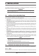
2. INSTALLATION This chapters illustrates the instructions on mechanical and electrical connections of the Radar and the necessary software settings to operate it. WARNING In order for the Radar Antenna to communicate with the Chart Plotter, the software must be configured as explained in the Par. 2.7. 2.0 INSTALLATION CONSIDERATIONS Prior to the actual installation of the Radar Antenna, several factors must be considered to ensure maximum performance (see also Appendix B). a.
unit that are needed for installation or operation. The cable must remain attached. For ease of handling, coil the cable and place it on top of the scanner. Then secure it with tape. Invert the scanner and make sure the four mounting holes are clear to accept bolts. Working at higher elevations may become necessary while installing the scanner unit. Observe safety measures and take sufficient precaution to avoid personal injury or damage to the equipment. 2.
12-24VDC White Black Black JUNCTION BOX Orange Brown Yellow Red EXTERNAL SWITCH Blue Green Figure 2.3 - Antenna Cable 2.4 CONNECTION PROCEDURE NOTE In the following procedure the small wires must be stripped and tinned, and then connected to the proper connections in the Radar Junction Box, and to pins on the On/Off control switch. If you are uncertain of your skill in completing these tasks, it is strongly advised to obtain the services of a qualified technician.
WAAS Radar On/Off Switch (Green & Blue wires from Radar Cable) Radar Cable GPS Char t CP300 Power / Data Swiched DC Power Figure 2.4 - Example of Connection Procedure for CP300 2.5 RADAR JUNCTION BOX CONNECTIONS Referring to the diagram below, connect the color coded wires from the Radar cable to the designated place on Terminal strip A in Radar Junction Box as follows. TERMINAL C Radar Cable TERMINAL A Chart Plotter MOUNTING INSTRUCTIONS 1. Open the box unscrewing the 4 bottom screws. 2.
Standard Horizon Chart Plotter. Do not omit the in-line fuse unless a dedicated and fused terminal is available. If so, install a 5 Amp fuse. Terminal Strip C - Radar Cable This terminal strip is used to connect the Radar Antenna. 2.6 RADAR ANTENNA CONNECTIONS 2.6.
2.7 CHART PLOTTER CONNECTIONS AND SET UP The following instructions refer to Dome Antennas; refer to Open Array for connections. 2.7.0 CP180 & CP180i Connections A switch MUST be connected to turn the Radar On or Off Radar Switch PWR & ACC 1 Cable PLOTTER CABLE RADAR CABLE WIRE COLOR FUNCTION GREEN GND No connection AUX OUT+ BROWN (Port 1) OUTPUT+ (TX+) BLUE (Port 1) INPUT+ (RX+) BLACK POWER- /GND RED POWER+ WIRE COL.
2. 3. 4. 5. 6. Move the ShuttlePoint knob to highlight ADVANCED SETUP and press [ENT]. Move the ShuttlePoint knob to highlight IN/OUT CONNECTIONS and press [ENT]. Move the ShuttlePoint knob to highlight PORT 1 INPUT and press [ENT]. Move the ShuttlePoint knob up/down to select RADAR and press [ENT]. Press [CLR] or move the ShuttlePoint knob to the left until the Chart page is shown. 2.7.
1. From the Chart page, press [MENU]. Move the ShuttlePoint knob to highlight SETUP MENU and press [ENT]. 2. Move the ShuttlePoint knob to highlight ADVANCED SETUP and press [ENT]. 3. Move the ShuttlePoint knob to highlight IN/OUT CONNECTIONS and press [ENT]. 4. Move the ShuttlePoint knob to highlight PORT 1 INPUT and press [ENT]. 5. Move the ShuttlePoint knob up/down to select RADAR and press [ENT]. 6. Press [CLR] or move the ShuttlePoint knob to the left until the Chart page is shown. 2.7.
Port Setup When an optional Radar Antenna is connected, Port 1 of the NMEA In/Out Communication Setup menu must be changed to RADAR as shown below for communications. 1. From the Chart page, press [MENU]. Move the ShuttlePoint knob to highlight SETUP MENU and press [ENT]. 2. Move the ShuttlePoint knob to highlight ADVANCED SETUP and press [ENT]. 3. Move the ShuttlePoint knob to highlight IN/OUT CONNECTIONS and press [ENT]. 4. Move the ShuttlePoint knob to highlight PORT 1 INPUT and press [ENT]. 5.
Port Setup When an optional Radar Antenna is connected, Port 1 of the NMEA In/Out Communication Setup menu must be changed to RADAR as shown below for communications. 1. From the Chart page, press [MENU]. Move the ShuttlePoint knob to highlight SETUP MENU and press [ENT]. 2. Move the ShuttlePoint knob to highlight ADVANCED SETUP and press [ENT]. 3. Move the ShuttlePoint knob to highlight IN/OUT CONNECTIONS and press [ENT]. 4. Move the ShuttlePoint knob to highlight PORT 1 INPUT and press [ENT]. 5.
Port Setup When an optional Radar Antenna is connected, Port 1 of the NMEA In/Out Communication Setup menu must be changed to RADAR as shown below for communications. 1. From the Chart page, press [MENU]. Move the ShuttlePoint knob to highlight SETUP MENU and press [ENT]. 2. Move the ShuttlePoint knob to highlight ADVANCED SETUP and press [ENT]. 3. Move the ShuttlePoint knob to highlight IN/OUT CONNECTIONS and press [ENT]. 4. Move the ShuttlePoint knob to highlight PORT 1 INPUT and press [ENT]. 5.
Page 22 Radar Installation Manual
3. TECHNICAL SPECIFICATIONS Features Antenna Peak Power Output Beam Width (degree) Horizontal Beam Width (degree) Vertical Rotation (RPM) 3.0 MDS-8 MDS-9 MDS-10-4/MDS-10-5 12.4 Inch-Dome 20 Inch-Dome 23.5 Inch-Dome 47.25/59.1 Inch-Open Array 2KW 7° 25° 30 2KW 4.7° 25° 30 4KW 4.0° 25° 24 4KW 2.4°/1.7° 25° 24 MDS-1 3.0.
3.0.1 Dimensions and Mounting Figure 3.0.1 - Radar MDS-1 (I) Weight: 4.5 kg (10 lb) without cable Weight: 5.5 kg (12.5 lb) 10m cable included Figure 3.0.
3.1 MDS-8 3.1.0 Antenna Unit · · · · · · · · · · · · · · · · · · · · · · Power supply Power consumption Preheat times Aerial Peak power output Transmitting frequency Beam width (degree) : : : : : : Horizontal : Vertical : Sidelobes Within +/-10° : Rotation : Pulse Length (μsec)/PRF (Hz) S : M, M1 : L, M2 : IF center frequency : IF bandwidth S : M, M1 : L, M2 : Noise figure : Operating Temperature : Operation in wind (relative) : Water Resistance : Preheat times output (by 5 sec step) : 3.1.1 10.
Weight: 8.1 kg (18.0 lb) 10m cable included Weight: 6.8 kg (15.0 lb) without cable Figure 3.1.1a - Radar MDS-8 (II) 3.2 MDS-9 3.2.0 · · · · · · · · · · · · · · · · · · · Antenna Unit Power supply Power consumption Preheat times Aerial Peak power output Transmitting frequency Beam width (degree) Sidelobes Within +/-10° Rotation Pulse Length (μsec)/PRF (Hz) IF center frequency IF bandwidth Page 26 : : : : : : Horizontal : Vertical : : : S : M, M1 : L, M2 : L, L1 : : S : M, M1 : L, M2 : L, L1 : 10.
· · · · · Noise figure Operating Temperature Operation in wind (relative) Water Resistance Preheat times output (by 5 sec step) 3.2.1 : : : : : 6.0dB or less -25°C ~ +55°C 100 knots IPX6 (IEC60529) 115 sec to 5 sec Dimensions and Mounting Figure 3.2.1 - Radar MDS-9 (I) Weight: 9.7 kg (21.5lb) 10m cable included Weight: 8.4 kg (19.0lb) without cable Figure 3.2.
3.3 MDS-10-4/MDS-10-5 3.3.
3.3.1 Dimensions and Mounting Figure 3.3.1 - Radar MDS-10-4/MDS-10-5 (II) Weight: 21.2 Kg (47lb) 4 feet Weight: 21.9 Kg (49lb) 5 feet Figure 3.3.
Page 30 Radar Installation Manual
Appendix A. WHAT IS RADAR? A.0 GENERAL The word “radar” is an acronym for “RAdio Detecting And Ranging.” In very simple terms, this is how it works. A radio transmitter sends a quick microwave pulse, and then a receiver listens for that signal’s echo when it is bounced back from something in its path. The returning signal is processed by a computer to determine its relative distance, position and bearing. This information is graphically displayed on a screen for you to see.
Beam Side lobe Main Side Antenna Figure A.0.1 - Antenna pattern A.1 CHARACTERISTICS OF RADAR WAVE Radio waves travel out from the antenna while bending slightly along the earth’s surface. The amount they bend depends on atmospheric conditions. The sight distance of a radar generally is about 6% longer than the optical sight distance and is calculated using this equation: Radar sight distance (NM) = 2.22 ( antenna height (m) + target height (m)) Line of sight h1 Radar Radio Wave h2 Earth Figure A.
create a shdow zone behind it and prevent you from seeing targets on the other side. More importantly, if a mast or some part of the boat’s superstructure is in the path of the antenna’s sweep, this will also create a shadow zone. No targets will be recognized behind it and it could create a dangerous situation. A.1.2 False echoes Sometimes radar will display targets on screen that do not exist in the real world. You should be aware of how and why this happens.
3 1 Real echo { HU Multiple echoes Figure A.1.2a - Multiple Echoes False echoes caused by side lobe An antenna’s side lobe emissions are low power, and will not register distant targets. However, if there is a strong reflecting target near your boat, it sometimes may appear as a circular-arc false echo on the screen. WARNING When near large targets or land, your boat's mast may sometimes appear as circular-arc shaped false echo.
or eliminate the interference. 3 1 HU Radar interference Figure A.1.
Page 36 Radar Installation Manual
Appendix B. INSTALLATION B.0 B.0.0 MORE INSTALLATION CONSIDERATIONS Shifting from keel line By shifting the scanner position from the keel line to the starboard side of the boat, it is possible to move shadow zones to the port side. This makes it possible to keep a clear view to the bow. The distance to be shifted can calculated using the following equation: Ls = 0.4R+D/2 [m] (when R<15m) Ls = 0.
B.1 INSTALLING SCANNER UNIT Use a mounting base such as the ones shown in Figure B.1, or you can install the scanner directly to a roof or other flat surface. Be certain you keep the water drain tube clear. It’s located at the bottom of the scanner unit. NOTE If the mounting bracket or surface has a curvature of more than 2mm, use spacers with the mounting bolts to prevent stress on the scanner housing. Do not use an edge that might trap water. Figure B.
INDEX A Aerial ........................................... 23, 25, 26, 28 Antenna ........................................................... 31 ANTENNA CONNECTIONS ........................... 15 Antenna Unit ............................... 23, 25, 26, 28 B Backing up ...................................................... 21 Beam width ................................. 23, 25, 26, 28 C cable from Antenna ......................................... 12 CONNECTION PROCEDURE ........................
PLEASE NOTE The following "Limited Warranty" is for customers that have purchased products in the United States. For Limited Warranty details outside the United States, contact the dealer in your country.