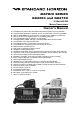
MATRIX SERIES GX2000 and GX2150 25 Watt VHF/FM Marine Transceivers Owner's Manual Integrated dual channel AIS (Automatic Identification System) receiver (GX2150) AIS (Automatic Identification System) receiver or transponder connection (GX2000) 4800 or 38400 NMEA baud rate selection for plotters with 1 NMEA port (GX2150) Able to use PA or Fog signaling when on AIS display (GX2150) True and Magnetic bearing selection on AIS display AIS target display: MMS
TABLE OF CONTENTS Quick Reference Guide ............................................................................................ 4 1 GENERAL INFORMATION ................................................................................ 5 2 PACKING LIST ................................................................................................... 6 3 OPTIONS .............................................................................................................
TABLE OF CONTENTS 10 GENERAL SETUP ........................................................................................... 77 10.1 DISPLAY ............................................................................................ 77 10.2 LOCAL DISTANCE RECEIVER ATTENUATOR .............................. 78 10.3 DIMMER ADJUSTING ....................................................................... 79 10.4 CONTRAST .......................................................................................
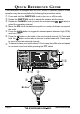
QUICK REFERENCE GUIDE This transceiver is equipped with the E2O (Easy-To-Operate) system. Basic operation may be accomplished by following the procedure below: Press and hold the PWR /VOL knob to turn on or off the radio. Rotate the PWR /VOL knob to adjust the speaker audio volume. Rotate the CHANNEL knob (or press the microphones / button) to select the operating channel. Move the SQL knob clockwise to squelch or counter clockwise un-squelch the radio.
1 GENERAL INFORMATION The STANDARD HORIZON MATRIX Series GX2000 and GX2150 Marine VHF/ FM Marine Transceivers are designed to be used in USA, International and Canadian Marine bands. The GX2000 and GX2150 can be operated from 11 to 16 VDC and has a switchable RF output power of 1 watt or 25 watts.
2 PACKING LIST When the package containing the transceiver is first opened, please check it for the following contents: GX2000 or GX2150 Transceiver Mounting Bracket and hardware Owner’s Manual DSC Warning Sticker Flush Mount Template Power Cord Dust Cover 3 OPTIONS MMB-84 ......................................................................... Flush-Mount Bracket RAM3B/W ....................... Remote-Access Microphone (CMP30Black/White) HC2000 .............................................
5 GETTING STARTED 5.1 PROHIBITED COMMUNICATIONS The FCC prohibits the following communications: • False distress or emergency messages: • Messages to “any boat” except in emergencies and radio tests; • Messages to or from a vessel on land; • Transmission while on land; • Obscene, indecent, or profane language (potential fine of $10,000). 5.2 ABOUT VHF RADIO The radio frequencies used in the VHF marine band lie between 156 and 158 MHz with some shore stations available between 161 and 163 MHz.
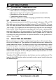
5.4 COAXIAL CABLE VHF antennas are connected to the transceiver by means of a coaxial cable – a shielded transmission line. Coaxial cable is specified by it’s diameter and construction. For runs less than 20 feet, RG-58/U, about 1/4 inch in diameter is a good choice. For runs over 20 feet but less than 50 feet, the larger RG-8X or RG213/U should be used for cable runs over 50 feet RG-8X should be used. For installation of the connector onto the coaxial cable refer to the figure below.
7. Estimate the present seaworthiness and condition of your vessel. 8. Give your vessel’s description: length, design (power or sail), color and other distinguishing marks. The total transmission should not exceed 1 minute. 9. End the message by saying “OVER”. Release the microphone button and listen. 10. If there is no answer, repeat the above procedure. If there is still no response, try another channel.
After a transmission, say “over,” and release the microphone’s push-to-talk (PTT) switch. When all communication with the other vessel is completed, end the last transmission by stating your Call Sign and the word “out.” Note that it is not necessary to state your Call Sign with each transmission, only at the beginning and end of the contact. Remember to return to Channel 16 when not using another channel. Some radios automatically monitor Channel 16 even when set to other channels or when scanning. 5.
The Automated Radio Check Service is currently available in the areas listed below. West Coast Northeast Mid-Atlantic North Carolina Florida Sea Tow Newport/LA - Ch. 27 Sea Tow San Diego - Ch. 27 Sea Tow Portland-Midcoast (Maine) - Ch. 27 Sea Tow Boston - Ch. 27 Sea Tow South Shore (Mass.) - Ch. 28 Sea Tow Rhode Island - Ch. 24 Sea Tow Eastern Long Island - Ch. 27 Sea Tow Huntington (N.Y.) - Ch. 27 Sea Tow Manasquan (N.J.) - Ch. 28 Sea Tow Northern Chesapeake (Md.) - Ch.
6 INSTALLATION 6.1 SAFETY / WARNING INFORMATION This radio is restricted to occupational use, work related operations only where the radio operator must have the knowledge to control the exposure conditions of its passengers and bystanders by maintaining the minimum separation distance of 0.89 m (2.92 feet). Failure to observe these restrictions will result in exceeding the FCC RF exposure limits. Antenna Installation: The antenna must be located at least 0.89 m (2.
6.3 MOUNTING THE RADIO 6.3.1 Supplied Mounting Bracket The supplied mounting bracket allows overhead or desktop mounting. Use a 13/64” (5.2-mm) bit to drill the holes to a surface which is more 0.4 inch (10 mm) thick and can support more than 3.3 lbs (1.5 kg) and secure the bracket with the supplied screws, spring washers, flat washers, and nuts. DESKTOP MOUNTING OVERHEAD MOUNTING 6.3.2 Optional MMB-84 Flush Mount Bracket 1.
6.4 ELECTRICAL CONNECTIONS CAUTION Reverse polarity battery connections will damage the radio! Connect the power cord and antenna to the radio. Antenna and Power Supply connections are as follows: 1. Mount the antenna at least 3 feet (1 m) away from the radio. At the rear of the radio, connect the antenna cable. The antenna cable must have a PL259 connector attached. RG-8/U coaxial cable must be used if the antenna is 25 feet (7.6 m) or more from the radio.
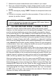
6.5 ACCESSORY CABLES 6.5.1 MATRIX GX2000 Connection The image and table below show the wires of the MATRIX (GX2000) and the connections to optional devices such as a PA Speaker (Horn), External Speaker, GPS Chart plotter and a AIS receiver or Transponder. The MATRIX uses NMEA 0183 protocol to communicate to a GPS chart plotter and a AIS device. GPS Chart Plotter connections are at 4800 baud and AIS device signalling is at 38400 baud sometimes called High Speed (HS).
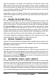
6.6 MATRIX AIS+ CONNECTIONS The image and table below show the wires of the MATRIX AIS+ (GX2150) and the connections to optional devices such as a PA Speaker (Horn), External Speaker and a GPS Chart plotter. The GX2150 uses NMEA 0183 protocol to share coordinates, DSC and AIS information to and from a GPS chart plotter. The GX2150 transfers targets to a GPS Chart plotter or PC at 38400 baud (sometimes called High Speed HS).
6.6.2 MATRIX AIS+ 38400 Baud Connections Use the image and table below when connecting to a GPS Chart plotter which has one NMEA 0813 ComPort.
GPS Connections (GX2000: 4800 baud) NMEA INPUT (GPS Information) • The GPS must have the NMEA Output turned on and set to 4800 Baud in the setup menu. If there is a selection for parity select none. • For further information on interfacing /setting up your GPS. Please contact the manufacturer of the GPS receiver. • GX2000 can read NMEA-0183 version 2.0 or higher. • The NMEA 0183 input sentences are GLL, GGA, RMC, and GNS (RMC sentence is recommended).
6.7 CHECKING GPS CONNECTIONS After connections have been made between the GX2000/GX2150 and the GPS, a small satellite icon will appear on the top right corner of the display and your current location (Latitude/Longitude) will be shown on the display. NOTE If there is a problem with the NMEA connection between the radio and the GPS, the GPS icon will blink continuously until the connection is corrected. 6.
6.9 CHANGING THE TIME AREA This menu selection allows the radio to show UTC time or your local time with the offset which is enabled in section “6.8 CHANGING THE GPS TIME”. 1. Press and hold down the key until “Setup Menu” appears, then select “GENERAL SETUP” with the CHANNEL knob. 2. Press the soft key, then rotate the CHANNEL knob to “TIME AREA”. 3. Press the soft key. 4. Rotate the CHANNEL knob to select “UTC” or “LOCAL”. 5. Press the soft key to store the selected setting.
6.11 CHANGING COG TO TRUE OR MAGNETIC Allows the GPS COG (Course Over Ground) and the BRG from a AIS target to be selected to show in True or Magnetic. Factory default is True however by following the steps below the COG can be changed to Magnetic. 1. Press and hold down the key until “Setup Menu” appears, then select “GENERAL SETUP” with the CHANNEL knob. 2. Press the soft key, then rotate the CHANNEL knob to select “MAGNETIC”. 3. Press the soft key. 4.
5. Referring to illustration below, make a 1.2” (30 mm) hole in the wall, then insert the Extension Cable into this hole. Connect the Gasket and Mount Base to the Extension Cable Connector using the Nut. 6. Drill the four Screw holes (approx. 2 mm) on the wall, then install the Mounting Base to the wall using four screws. 7. Put the Rubber Cap on to the Nut. The installation is now complete.
6.12.1 Connecting an External Speaker to the RAM3 Mic Cable In noisy locations and optional external speaker may be connected to the white speaker wires on the RAM3 (CMP30) routing cable. The RAM3 (CMP30) can drive the internal speaker or the external speaker one at a time. When connecting an external speaker, follow the procedure below to turn off the RAM3 (CMP30) audio and enable the external speaker wires on the RAM3 (CMP30) routing cable. 1.
7 CONTROLS AND INDICATORS NOTE This section defines each control of the transceiver. See illustration at the next page for location of controls. For detailed operating instructions refer to chapter 8 of this manual. 7.1 FRONT PANEL CHANNEL Knob Rotary knob is used to select channels and to choose menu items (such as the DSC menu, Radio Setup and DSC Setup menu). The / keys on the microphone can also be used to select channels and menu items.
SQL Knob (Squelch Control) Adjusting this control clockwise, sets the point at which random noise on the channel does not activate the audio circuits but a received signal does. This point is called the squelch threshold. Further adjustment of the squelch control will degrade reception of wanted transmissions. Soft Keys The 3 soft keys functions can be customized by the Setup Menu mode section “10.14 SOFT KEYS”.
Key Press the key briefly to recall channel 16 from any channel location. key to recall channel 9. Pressing the [16/9] key Press and hold the again reverts to the previous selected working channel. [DISTRESS] Key Used to send a DSC Distress Call. To send the distress call refer to section “9.3.1 Transmitting a DSC Distress Alert”. 7.2 REAR PANEL Never remove this rubber cap. When this rubber cap is removed, the water resistance performance is lost.
PA Speaker Connection Cable (Red & Shield) Connects the GX2000/GX2150 to a optional PA speaker. Refer to section “3 OPTIONS” for a list of optional STANDARD HORIZON Speakers. External Speaker Connection Cable (White & Shield) an external speaker. See section “3 OPTIONS” for a list of optional STANDARD HORIZON Speakers. DC Input Cable Connects the radio to a DC power supply capable of delivering 11 to 16V DC.
7.3 MICROPHONE PTT Switch (Push-To-Talk Switch) 1. When in radio mode and the PTT button pressed, the transmitter is enabled for voice communications to another vessel. 2. When PA mode is selected, pressing the PTT button allows your voice to be amplified and supplied to a connected PA horn. 3.
MEMO GX2000/GX2150 Page 29
8 BASIC OPERATION 8.1 RECEPTION 1. After the transceiver has been installed, ensure that the power supply and antenna are properly connected. 2. Press and hold the PWR /VOL knob until the radio turns on. 3. Rotate the SQL knob fully counterclockwise. This state is known as “squelch off”. 4. Turn up the PWR /VOL knob until noise or audio from the speaker is at a comfortable level. 5. Rotate the SQL knob clockwise until the random noise disappears. This state is known as the “squelch threshold.” 6.
8.4 SIMPLEX/DUPLEX CHANNEL USE Refer to the VHF MARINE CHANNEL CHART (page 117) for instructions on use of simplex and duplex channels. NOTE All channels are factory-programmed in accordance with FCC (USA), Industry Canada (Canada), and International regulations. Mode of operation cannot be altered from simplex to duplex or vice-versa. 8.
6. Press the soft key several times to return to radio operation. NOTE To show Position information, show AIS targets and use the Compass display: GX2150 - external GPS must be connected. GX2000 - external AIS receiver or transponder and a external GPS must be connected. 8.6 USA, CANADA, AND INTERNATIONAL MODE To change the channel group from USA to Canada or International: key until 1. Press and hold down the “Setup Menu” appears. 2. Rotate the CHANNEL knob to select “CH FUNCTION SETUP”. 2.
When an alert is received on a NOAA weather channel, scanning will stop and the transceiver will emit a loud beep to alert the user of a NOAA broadcast. Pess any key to stop the alert and receive the weather report. Press the soft key to return to the last selected channel. To disable the Weather Alert function, refer to section “11.6 WEATHER ALERT”. NOTE If the key is not pressed the alert will sound for 5 minutes and then the weather report will be received. 8.7.
8.9 PRESET CHANNELS (0 ~ 9): INSTANT ACCESS 10 Preset Channels can be programmed for instant access. Press the one of soft keys, then press the soft key to activate the preset channel bank. soft is pressed and no channels have been assigned, an alert If the beep will be emitted from the speaker. 8.9.1 Preset Channel Programming 1. Rotate the CHANNEL knob to select the channel to be programmed. 2.
5. Repeat steps 2 through 4 to delete the desired channels from Preset Channels “0” ~ “9”. 6. To finish the deleting the Preset Channel, press the soft key 8.10 SCANNING The GX2000/GX2150 will automatically scan channels programmed into Preset Channel Memory and also Scan Channel Memory, and last selected Weather Channel. When an incoming signal is detected on one of the channels during scan, the radio will pause on that channel, allowing you to listen to the incoming transmission.
8.10.2 Scan Memory Programming 1. Press and hold down the key until “Setup Menu” appears. 2. Rotate the CHANNEL knob to select “CH FUNCTION SETUP”. 3. Press the soft key, then rotate the CHANNEL knob to select “SCAN MEMORY”. soft key. 4. Press the 5. Rotate the CHANNEL knob to select a desired channel to be scanned, the press the soft key. “MEM” icon appears on the display, which indicates the channel has been selected to the scan channel. 6. Repeat step 5 for all the desired channels to be scanned. 7.
8.11 PA/FOG OPERATION The GX2000/GX2150 has a 30W Hailer built-in and can be used with any 4 Ohm PA Horns. Standard Horizon offers a small and a large PA horn called the 220SW and 240SW. When in Hail mode the PA speaker Listen’s Back (acts as a microphone and sends sound to the front panel speaker and the speaker mic: GX2150 only) through the PA horn speaker which provides two-way communications through the PA horn speaker. NOTE When in PA or FOG mode, the GX2000/GX2150 will receive: 1.
NOTE When in the PA HAIL mode it is possible to simultaneously use the AIS page by press the key. 8.11.2 FOG HORN Operation The user can select from “Underway”, “Stop”, “Sail”, “Tow”, “Aground”, “Anchor”, “Horn”, and “Siren”. 1. Press the one of the soft keys momentarily, then press the soft key. Note: The soft key may have to be pressed to see the soft key if the soft keys have not be customized. 2. Rotate the CHANNEL knob to select “FOG”, then press the soft key. 3.
8.11.3 Fog Signal Timing Chart TYPE UNDERWAY PATTERN One 5-second blasts every 120 seconds. Motor vessel underway and making way. Listen Back 120s STOP Two 5-second blasts (separated by 2 seconds) every 120 seconds. 5s Motor vessel underway but stopped (not making way). 5s Listen Back 2s SAIL 120s 2s One 5-second blasts followed by two 1second blasts (separated by 2 seconds) every 120 seconds.
8.12 INTERCOM OPERATION To access the following Intercom functions one of the soft keys must be setup as IC. Refer to section “10.14 SOFT KEYS”. In addition an optional RAM3 (CMP30) Remote Station Microphone must be connected to perform intercom functions between the GX2000/GX2150 and the RAM3 (CMP30). 8.12.1 Communication 1. Press the one of the soft keys momentarily, then press the soft key to enable the intercom mode.
8.13 VOICE SCRAMBLER If privacy of communications is desired, a CVS2500 4 code voice scrambler (VS) can be installed in the transceiver. Contact your Dealer to have a CVS2500 installed. Refer to the section “11.8 SCRAMBLER SETUP” to program the voice scrambler. 1. Select a channel that was programmed for scrambler mode (“Vs” and scrambler number will appear on the display). 2. Monitor the channel before transmitting. 3. Transmit the voice message. The signal sent will be scrambled.
9 DIGITAL SELECTIVE CALLING 9.1 GENERAL WARNING This radio is designed to generate a digital maritime distress and safety call to facilitate search and rescue. To be effective as a safety device, this equipment must be used only within communication range of a shorebased VHF marine channel 70 distress and safety watch system. The range of signal may vary but under normal conditions should be approximately 20 nautical miles. NOTE A DSC Warning sticker is included with the GX2000/GX2150.
How can I obtain an MMSI assignment? In the USA, visit the following websites to register: http://www.boatus.com/mmsi/ or http://seatow.com/boating_safety/mmsi.asp In the Canada, visit http://www.ic.gc.ca/epic/site/smt-gst.nsf/en/sf01032e.html or http://www.usps.org/php/mmsi/rules.php 9.2.2 Programming the MMSI WARNING A user MMSI can be inputted only once. Therefore please be careful not to input the incorrect MMSI number.
9.3 DSC DISTRESS ALERT The GX2000/GX2150 is capable of transmitting and receiving DSC Distress messages to all DSC radios. The GX2000/GX2150 may be connected to a GPS to also transmit the Latitude, Longitude of the vessel. 9.3.1 Transmitting a DSC Distress Alert NOTE To be able to transmit a DSC Distress Alert an MMSI number must be programmed, refer to section “9.2.2 Programming the MMSI.
9.3.1.1 Transmitting a DSC Distress Alert with Nature of Distress The GX2000/GX2150 is capable of transmitting a DSC Distress Alert with the following “Nature of Distress” categories: Undesignated, Fire, Flooding, Collision, Grounding, Capsizing, Sinking, Adrift, Abandoning, Piracy, MOB 1. Lift the red spring loaded DISTRESS cover and press the [DISTRESS] key. The “DISTRESS ALERT” menu will appear on the display. 2.
2. Press the soft key. 3. Enter the latitude/longitude of your vessel and your local UTC time in the 24-hour notation by the CHANNEL knob. Rotate the CHANNEL knob to select the number and press the soft key to move the cursor to the next character. You may backspace the cursor by pressing the soft key, if you make a mistake. 4. When you have completed your selection, press and hold in the soft key for two seconds to save the setting. 5. Press and hold the [DISTRESS] key.
9.3.1.3 Pausing a DSC Distress Call After a DSC Distress call is transmitted, the DSC distress call is repeated every 4 minutes until the call is canceled by the user or until the radio is turned on and off again. The GX2000/GX2150 has provision to suspend (Pause) the retransmitting of the distress call by the procedure below. 1. After the distress call is transmitted, the radio will show the top display to the right.
(select the letter/number by rotating the CHANNEL knob and move the Received DISTRESS cursor by pressing the / soft key). Name:VERTEX ID:123456789 6. The ID is the MMSI from the vessel in distress. Since: 01:03 -DISTRESS INFO7. When you are finished entering the waypoint name, Nature of:Undesignate DIST ID:123456789 WPT QUIT soft key to replace the press and hold the display to the “WAYPOINT” Screen.
9.4 ALL SHIPS CALL The All Ships Call function allows contact to be established with DSC equipped vessels without having their MMSI in the individual calling directory. Also, priority for the call can be designated as Urgency or Safety. URGENCY Call: This type of call is used when a vessel may not truly be in distress, but have a potential problem that may lead to a distress situation. This call is the same as saying PAN PAN PAN on channel 16.
9.4.2 Receiving an All Ships Call 1. When an all ships call is received, an emergency alarm will sound. The display shows the MMSI of the vessel transmitting the All Ships Call and the radio will change to the requested channel after 10 seconds. 2. Press any key to stop the alarm. 3. Monitor the requested channel until the ALL SHIPs voice communication is completed. On the display you will notice 3 soft key selections. These selections are described below: a. : Accept to auto switching to requested channel.
9.5 INDIVIDUAL CALL This feature allows the GX2000/GX2150 to contact another vessel with a DSC VHF radio and automatically switch the receiving radio to a desired communications channel. This feature is similar to calling a vessel on CH16 and requesting to go to another channel (switching to the channel is private between the two stations). Up to 80 Individual contacts may be programmed. 9.5.
desired number and move one space to the right by pressing the soft key. Repeat this procedure until all nine space of the MMSI number are entered. 11. If a mistake was made entering in the MMSI number soft key until the wrong number is selected, repeat pressing the then rotate the CHANNEL knob to correct the entry. 12. To store the data entered, press and hold the soft key. 13. To enter another individual address, repeat steps 5 through 12. soft key several times to return to radio operation. 14.
TO COMPLY” or “UNABLE”. 6. Press the soft key to store the selected setsoft key several times ting, then press the to return to radio operation. 9.5.4 Individual/Group Call Ringer Setup When a Individual Call or Group Call is received the radio will produce a ringing sound for 2 minutes. This selection allows the Individual Call ringer time to be changed. 1. Press and hold down the key until “Setup Menu” appears. 2. Rotate the CHANNEL knob to select “DSC SETUP” menu. soft key, then select “INDI3.
9.5.5 Transmitting an Individual Call This feature allows the user to contact another vessel with a DSC radio. This feature is similar to calling a vessel on CH16 and requesting to go to another channel. 9.5.5.1 Individual Call using the Individual Directory 1. Press the key. The “DSC Menu” will appear. 2. Rotate the CHANNEL knob to select “INDIVIDUAL”. (To cancel, press the soft key.) 3. Press the soft key. The transceiver will beep, and the “Last Individual Call” will appear.
9.5.5.2 Individual Call by Manually Entering a MMSI You may enter an MMSI number manually to contact without storing it in the Individual Directory. 1. Press the key. The “DSC Menu” menu will appear. 2. Rotate the CHANNEL knob to select “INDIVIDUAL”. soft key.) (To cancel, press the 3. Press the soft key. NOTE If you have transmitted a Individual call before, the radio will show the name of the last person you called as shown in the display at the right.
and a ringing tone sounds. 12. Press the soft key to listen to the channel to make sure it is not busy, then press the microphone’s PTT switch and talk into the microphone to the other vessel. 9.5.6 Receiving an Individual Call When a Individual DSC call is received, the radio will automatically respond (Default setting) to the calling ship, and switch to the requested channel for voice communications. Refer to section “9.5.
9.6 DSC LOG OPERATION The GX2000/GX2150 logs received distress calls and individual calls. The DSC Log feature is similar to an answer machine where calls are recorded for review and a “ ” icon will appear on the radios display. The GX2000/GX2150 can store up to the latest 26 Distress, and up to the latest 64 other calls (Individual, Group, All Ship etc.). 9.6.1 Reviewing a Logged DSC Distress Call The GX2000 / GX2150 radios allows logged DSC distress call to be reviewed. key. The “DSC menu” will appear.
9.6.2 Reviewing a Logged All Ship or Individual Call Reviewing a logged All ship or Individual call. 1. Press the key. The “DSC Menu” will appear. 2. Rotate the CHANNEL knob to select “DSC LOG” menu. soft key, then rotate the CHAN3. Press the NEL knob to select “OTHER CALL LOG”. soft key, then rotate the 4. Press the CHANNEL knob to select the station (name or MMSI number) you want to review and/or call back.
9.6.3 Deleting a Call from the “DSC LOG” Directory 1. Press the key. The “DSC Menu” will appear. 2. Rotate the CHANNEL knob to select “DSC LOG” menu. 3. Press the soft key, then rotate the CHANNEL knob to select “LOG DELETE” menu. soft key, then rotate the 4. Press the CHANNEL knob to select the category (“DISTRESS LOG” or “OTHER CALL LOG”) to be deleted. 5. Press the CHANNEL knob.
9.7 GROUP CALL This feature allows the user to contact a group of specific vessels (example members of a yacht club) using DSC radios with Group call function to automatically switch to a desired channel for voice communications. This function is very useful for yacht clubs and vessels traveling together that want to collectively make announcements on a predetermined channel. Up to 32 Group MMSI may be programmed. 9.7.
5. Press the soft key. 6. Rotate the CHANNEL knob to scroll through the first letter of the name of the group you want to reference in the directory. 7. Press the soft key to store the first letter in the name and step to the next letter to the right. 8. Repeat step 6 and 7 until the name is complete. The name can consist of up to eleven characters, if you do not use all eleven characters press the soft key to move to the next space. This method can also be used to enter a blank space in the name.
6. 7. 8. 9. NEL knob to select the operating channel you want to communicate on, then press the soft key. If the channel you want is soft key, then not shown, press the rotate the CHANNEL knob to select the operating channel you want to communicate on, then press the soft key. Press the soft key to transmit the Group Call signal. When the Group Call signal is sent, the display will be as shown in the illustration at the right.
9. 10. 11. 12. 13. number, repeat pressing the soft key until the wrong number is selected, then rotate the CHANNEL knob to correct the entry. When finished entering the MMSI number, press and hold the soft key. Rotate the CHANNEL knob to select the operating channel you want to communicate on, then press the soft key. If the channel you want is not shown, press the soft key, then rotate the CHANNEL knob to select the operating channel you want to communicate on, then press the soft key.
9.8 POSITION REQUEST Advancements in DSC have made it possible to poll the location of another vessel and show the position of that vessel on the display of the GX2000/ GX2150. Standard Horizon has taken this feature one step further, if any compatible GPS chart plotter is connected to the GX2000/GX2150, the polled position of the vessel is shown on the display of the GPS chart plotter making it easy to navigate to the location of the polled vessel.
9.8.2 Position Request Ringer Setup The GX2000/GX2150 has the capability to turn off the Position Request ringer. 1. Press and hold down the key until “Setup Menu” appears. 2. Rotate the CHANNEL knob to select “DSC SETUP” menu. soft key, then select “DSC 3. Press the BEEP” with the CHANNEL knob. soft key, then select “POS 4. Press the Request” with the CHANNEL knob. 5. Press the soft key, then select “Off” with the CHANNEL knob. 6. Press the soft key to store the selected setting.
9.8.3.2 Position Request by Manually Entering a MMSI This feature allows you to request the position of vessel by manually entering the MMSI of the ship you want to send your position to. 1. Press the key. The “DSC Menu” will appear. 2. Rotate the CHANNEL knob to select “POS REQUEST”. soft key to show the “Last 3. Press the Individual Call”. 4. Rotate the CHANNEL knob to select the “MANUAL,” then press the soft key. 5.
Manually reply: 1. When a position request call is received from another vessel, the display will be as shown in the illustration at the right. 2. A ringing alarm sounds 4 times. To send your vessels position to the requesting vessel, press the soft key. Or to exit from position request display, press the soft key.
9.9 POSITION REPORT The feature is similar to Position Request, however instead of requesting a position of another vessel this function allows you to send your position to another vessel. Your vessel must have an operating GPS receiver connected for the GX2000/GX2150 to send the position. NOTE To transmit a Position Report Call, a GPS must be connected to the radio and the GX2000 / GX2150 Individual directory must be programmed with stations you wish to send your position to.
5. Press the soft key to send your position to the selected vessel. 6. Press the soft key to return to radio operation. 9.9.2.2 DSC Position Report Call manually entering a MMSI This feature allows you to send your position to another vessel by manually entering the MMSI of the ship you want to send your position to. 1. Press the key. The “DSC Menu” will appear. 2. Rotate the CHANNEL knob to select “POS REPORT”. (To cancel, press the soft key.) 3. Press the soft key.
9.9.3 Receiving a DSC Position Report Call When another vessel transmits their vessels location to the GX2000/GX2150 the following will happen: 1. A ringing sound will be produced when the call is received and NMEA sentences DSC, DSE are outputted so the position can be shown on a chart plotter or a computer. 2. Press the key to stop ringing. 3. Rotate the CHANNEL knob to see position information of the station. 4. To exit to radio mode, press the soft key. 9.9.
9.9.6 Saving a Position Report as a Waypoint The GX2000/GX2150 can save a Position Report call in the radios memory as a waypoint. 1. After the Position Report call has been received: Press the soft key. 2. Rotate the CHANNEL knob to change the first letter in the name of the waypoint and press the soft key. 3. Repeat step 2 until the WPT Name is entered. 4. Press and hold the soft key to save the waypoint into memory. 9.9.7 Navigating to a saved waypoint 1.
9.10 MANUAL INPUTTING OF THE GPS LOCATION (LAT/LON) You may send the Latitude/Longitude of your vessel manually even if the GX2000/GX2150 is not connected the GPS receiver unit. After the position is entered, transmitting a DSC Distress, Position Request, or Position Report will contain the manually entered position. 1. Press and hold down the key until “Setup Menu” appears. 2. Rotate the CHANNEL knob to select “DSC SETUP” menu. 3. Press the soft key, then select “POSITION INPUT” with the CHANNEL knob.
9.11 AUTO DSC POLLING The GX2000/GX2150 has the capability to automatically track four stations programmed into the Indvidual directory. The following procedure allows the time interval between position requests to be setup. 9.11.1 Polling Time Interval Setup 1. Press and hold down the key until “Setup Menu” appears. 2. Rotate the CHANNEL knob to select “DSC SETUP” menu. soft key, then select “AUTO 3. Press the DSC INTERVAL” with the CHANNEL knob. 4.
and CALL 4 entries. 7. When finished, press the soft key numerous times to exit to the radio mode. 9.11.3 Enable/Disable Auto DSC Polling 1. Press the key. The “DSC Menu” will appear. 2. Rotate the CHANNEL knob to select “AUTO POS POLLING”, then press the soft key. 3. Rotate the CHANNEL knob to select the “ACTIVAsoft key. TION”, then press the 4. Select “START” to enable transmissions to the stations or “STOP” to disable transmissions to stations. 5. Press the soft key. 6.
9.12 DSC TEST This function is used to contact another DSC equipped vessel to ensure the DSC functions of the radio are operating. NOTE To use this feature, the radio you will be transmitting the test call to needs to have the DSC Test feature. To perform the DSC test you will need to enter a MMSI of another vessel into the Individual directory or manually enter in the MMSI using the procedure below. 9.12.1 Programming MMSI into Individual Directory Refer to section “9.5.
9.12.3 DSC Test Call by Manually Entering a MMSI 1. Press the key. The “DSC Menu” will appear. 2. Rotate the CHANNEL knob to select “DSC TEST”, then press the soft key. 3. Rotate the CHANNEL knob to select “MANUAL” and press the soft key. 4. Rotate the CHANNEL knob to select the first digit in the MMSI and press the soft key. 5. Repeat step 4 until all the numbers of the MMSI are shown on the display. soft key to show 6. Press and hold the the Test Call page. 7.
10 GENERAL SETUP The optional RAM3 (CMP30) Remote Station Microphone can also change the SETUP menu using the following procedure. 10.1 DISPLAY The GX2000/GX2150 can select additional screens other than the default normal (Radio) display by using the procedure below. “NORMAL” DISPLAY 1 “AIS” DISPLAY 1 “WAYPOINT” DISPLAY “COMPASS” DISPLAY 1 “GPS STATUS” DISPLAY 2 NOTE 1.
NOTE To show Position information, show AIS targets and use the Compass display: GX2150 - external GPS must be connected. GX2000 - external AIS receiver or transponder and a external GPS must be connected. 10.2 LOCAL DISTANCE RECEIVER ATTENUATOR In some areas, signals from external sources may cause interference to receiving marine transmissions.
10.3 DIMMER ADJUSTING This menu selection adjusts the backlight intensity. 1. Press and hold down the key until “Setup Menu” appears. 2. Rotate the CHANNEL knob to select “GENERAL SETUP” menu. 3. Press the soft key, then select “DIMMER” with the CHANNEL knob. 4. Press the soft key. 5. Rotate the CHANNEL knob to select the desired level (“HIGH” is default). When “OFF” is selected, the lamp is turned off. 6. Press the soft key to store the selected level. 7.
10.5 TIME OFFSET Sets the time offset between local time (with inputted offset) and UTC (without time offset) shown on the display. Time is displayed only when an optional GPS Chart Plotter is connected. 1. Press and hold down the key until “Setup Menu” appears, then select “GENERAL SETUP” with the CHANNEL knob. 2. Press the soft key, then select “TIME OFFSET” with the CHANNEL knob. 3. Press the soft key, then rotate the CHANNEL knob to select time offset of your location.
10.6 TIME AREA This menu selection allows the radio to show UTC time or local time with the offset. 1. Press and hold down the key until “Setup Menu” appears, then select “GENERAL SETUP” with the CH knob. 2. Press the soft key, then rotate the CHANNEL knob to “TIME AREA”. 3. Press the soft key. 4. Rotate the CHANNEL knob to select “UTC” or “LOCAL”. 5. Press the soft key to store the selected setting. soft key several times to return to 6. Press the radio operation. 10.
10.8 UNIT OF MEASURE Allows Navigation and AIS displays to be shown in “Knot”, “Mile/Hour” or “KiloMeter/Hour” (for speed) and “Nautical Mile” or “Kilo-Meter” (for distance). NOTE A GPS must be connected to the radio to be able to show SPEED and DISTANCE. 1. Press and hold down the key until “Setup Menu” appears, then select “GENERAL SETUP” with the CHANNEL knob. 2. Press the soft key, then rotate the CHANNEL knob to select “UNIT OF MEASURE”. 3. Press the soft key. 4.
10.10 NMEA DATA IN/OUT This section is used to setup the NMEA 0183 baud rate of the GPS input (Blue wire) and DSC output (Gray wire). The default setting is 4800 BPS. When 38400 BPS is selected the AIS sentences (VDM) and DSC sentences (DSC & DSE) both are output on the Gray wire after a DSC Distress, Position Request or AIS transmission is received. This Setup Menu works only in GX2150. 1. Press and hold down the key until “Setup Menu” appears, then select “GENERAL SETUP” with the CHANNEL knob. 2.
10.12 FOG ALERT TONE FREQUENCY The function allows the radio to be setup to send the proper fog frequency which is dependant on vessel size, shown below: 70 - 200Hz: Vessel that are 200 meters or more in length 130 - 350Hz: Vessel that are 75 Meters but less than 200 meters or more in length 250 - 525Hz: Vessel that are 66 Feet (20 Meters) but less than 247.5 Feet (75 Meters) in length 250 - 525Hz: Vessel that are 39.6 Feet (12 Meters) but less than 66 Feet (20 Meters) in length 1.
10.13 STATION NAME This function allows you to change the name of the radio or second station microphone. Example: “Radio - Cabin”, “RAM1 - Flybridge”. 1. Press and hold down the key until “Setup Menu” appears, then select “GENERAL SETUP” with the CHANNEL knob. 2. Press the soft key, then rotate the CHANNEL knob to select “STATION NAME”. 3. Press the soft key. 4. With the second station microphone connected, rotate the CHANNEL knob to select the Unit (“Radio” or “RAM1”) to be named, then press the soft key.
10.14 SOFT KEYS This menu item allows selection of the number of soft keys, soft key selection and how long the display will show the soft key icon after a soft key is pressed. 10.14.1 Selecting the Number of Soft Keys 1. Press and hold down the key until “Setup Menu” appears, then select “GENERAL SETUP” with the CHANNEL knob. 2. Press the soft key, then rotate the CHANNEL knob to “SOFT KEY”. 3. Press the soft key, then rotate the CHANNEL knob to “NUMBER OF SOFT KEYS”. soft key, then rotate the 4.
10.14.3 Selectiong How Long the Soft Keys are Shown 1. Press and hold down the key until “Setup Menu” appears, then select “GENERAL SETUP” with the CHANNEL knob. 2. Press the soft key, then rotate the CHANNEL knob to “SOFT KEY”. 3. Press the key, then rotate the CHANNEL knob to select “KEY TIMER” (selects how long the soft key icon will be shown on the display after a soft key is pressed, default is 5 seconds). 4. Press the soft key, then rotate the CHANNEL knob to select the time.
11 CHANNEL FUNCTION SETUP 11.1 CHANNEL GROUP This section selects a channel group from USA, Canada, and International. 1. Press and hold down the key until “Setup Menu” appears. 2. Rotate the CHANNEL knob to select “CH FUNCTION SETUP”. 3. Press the soft key, then rotate the CHANNEL knob to select “CH GROUP”. soft key. 4. Press the 5. Rotate the CHANNEL knob to select desired channel group “USA”, “INTL”, or “CANADA”. 6. Press the soft key to store the selected setting. 7.
11.3 SCAN TYPE This selection is used to select the scan mode between “Memory Scan” and “Priority Scan”. The default setting is Priority Scan. 1. Press and hold down the key until “Setup Menu” appears. 2. Rotate the CHANNEL knob to select “CH FUNCTION SETUP”. soft key, then select “SCAN TYPE” 3. Press the with the CHANNEL knob. 4. Press the soft key. 5. Rotate the CHANNEL knob to select “PRIORITY SCAN” or “MEMORY SCAN”. 6. Press the soft key to store the selected setting. 7.
11.5 PRIORITY CHANNEL By default the radio priority channel is set to channel 16. This procedure allows the radio to use a different priority channel used when priority scanning. 1. Press and hold down the key until “Setup Menu” appears. 2. Rotate the CHANNEL knob to select “CH FUNCTION SETUP”. soft key, then select “PRIORITY CH” 3. Press the with the CHANNEL knob. 4. Press the soft key. 5. Rotate the CHANNEL knob to select the desired channel to be a priority. 6.
11.7 CHANNEL NAME When radio mode (NORMAL) is selected, the display will show a name under the channel number. This name describes the use of the channel. The radio has the capability to customize the name by the procedure below. Example: CH69 PLEASURE to HOOKUP 1. Press and hold down the key until “Setup Menu” appears. 2. Rotate the CHANNEL knob to select “CH FUNCTION SETUP”. 3. Press the soft key, then select “CH NAME” with the CHANNEL knob. 4. Press the soft key. 5.
11.8 SCRAMBLER SETUP NOTE Operates only when the optional CVS2500 is installed. This menu will not appear unless a CVS2500 is installed. 1. Press and hold down the key until “Setup Menu” appears. 2. Rotate the CHANNEL knob to select “CH FUNCTION SETUP”. soft key, then select “SCRAMBLER” 3. Press the with the CHANNEL knob. 4. Press the soft key. 5. Rotate the CHANNEL knob to select the channel to be scrambled and press the soft key. 6. Rotate the CHANNEL knob to select the scrambler code.
11.9 DEMO MODE This mode is used by Standard Horizon sales persons and dealers to demonstrate radio, DSC and AIS functions in show rooms or at boat shows. Demo mode allows Latitude, longitude and time to be entered to simulate radio displays. When DEMO mode is enabled, the radio display will automatically switch from NORMAL, COMPASS, AIS and WAYPOINT displays. NOTE When demo mode is enabled and the radio is turned off and back on the radio will still be in DEMO mode. 1.
12 DSC SETUP 12.1 INDIVIDUAL DIRECTORY The GX2000/GX2150 has a DSC directory that allows you to store a vessel or person’s name and the MMSI number associated with vessels you wish to transmit Individual calls, Position Requests and Position Send transmissions. To transmit an Individual call you must program this directory with information of the persons you wish to call, similar to a cellular phones telephone directory. Refer to section “9.5.1 Individual / Position Call Directory Setup” for programming.
14.6 POSITION REPLY The GX2000/GX2150 can be set up to automatically (default setting) or manually send your position when requested by another vessel. This selection is important if you are concerned about someone polling the position of your vessel that you may not want to. In the manual mode you will see the MMSI or persons name shown on the display allowing you to choose to send your position to the requesting vessel. Refer to section “9.8.1 Position Reply Setup” for setting. 12.
13 AIS/COMPASS SETUP 13.1 AUTOMATIC IDENTIFICATION SYSTEM (AIS) NOTE The MATRIX AIS+ GX2150 does not require a special marine VHF antenna to receive AIS transmissions. The MATRIX AIS+ GX2150 does not transmit AIS signals, it is NOT recommended to use an antenna dedicated for AIS operation. The Automatic Identification System (AIS) is a short range coastal tracking system. AIS is intended to assist in collision avoidance by seeing positions and courses of AIS equipped vessels around your vessel.
13.2 DIRECTION This function allows you to select the top of the AIS compass to be orientated in Course Up or North Up. 1. Press and hold down the key until “Setup Menu” appears. 2. Rotate the CHANNEL knob to select “AIS/ COMPASS SETUP”. soft key, then select “DIRECTION” 3. Press the with the CHANNEL knob. 4. Press the soft key. 5. Rotate the CHANNEL knob to select “NORTH UP” or “COURSE UP”. 6. Press the soft key to store the selected setting. 7.
13.4 CPA ALARM This function allows you to set the CPA (Closest Point of Approach) alarm distance. : CPA means the positions at which two moving vessels reach their closest possible distance. 1. Press and hold down the key until “Setup Menu” appears. 2. Rotate the CHANNEL knob to select “AIS/ COMPASS SETUP”. 3. Press the soft key, then select “CPA ALARM” with the CHANNEL knob. soft key. 4. Press the 5.
4. Press the soft key. 5. Rotate the CHANNEL knob to select the time that the TCPA alarm will sound. 6. Press the soft key, then rotate the CHANNEL knob to set the Alarm item to “On”. 7. Press the soft key to store the selected setting. 8. Press the soft key several times to return to radio operation. NOTE The alarm will sound until it is disabled (1) by pressing any key, (2) following the steps above and in step 6 select “Off” or (3) when the ship is out of the selected TCPA alarm time.
13.7 AIS OPERATION The GX2150 is equipped with an AIS (AUTOMATIC IDENTIFICATION SYSTEM) receiver and can display AIS targets around your vessel on the radios display. Therefore, you can identify and avoid other large vessels nearby your vessel. The GX2000 can also show AIS targets, however a separate AIS receiver or transponder with NMEA VDM 34800 baud must be connected to the accessory cable.
13.7.1 Transmitting and Individual Call to an AIS Ship It is possible for the GX2000 or GX2150 to transmit a DSC Individual call to a received AIS target by the procedure below: 1. Press the one of the soft keys momentarily, then press the soft key. 2. Rotate the CHANNEL knob to select the operating channel you want to communicate on and press the CHANNEL knob.
14 WAYPOINTS The GX2000/GX2150 is capable of storing up to 100 waypoint and navigating to them using the compass page. In addition DSC distress calls with position or a position received from a another DSC radio using DSC polling can be navigated to. 14.1 MARKING A POSITION This feature allows the radio to mark the current position of the vessel. 1. Press and hold down the key until “Setup Menu” appears. 2. Rotate the CHANNEL knob to select “WAYPOINT SETUP”. soft key, then select “WAYPOINT 3.
14.2 ADDING A WAYPOINT 1. Press and hold down the key until “Setup Menu” appears. 2. Rotate the CHANNEL knob to select “WAYPOINT SETUP”. 3. Press the soft key, then select “WAYPOINT DIRECTORY” with the CHANNEL knob. 4. Press the soft key, then select “ADD” with the CHANNEL knob. soft key. 5. Press the 6. Enter the Waypoint Name, by rotating the CHANNEL knob to select the first letter. 7. Press the soft key to store the first letter and to move to the second letter in the name. 8.
14.3 EDITING A WAYPOINT This function allows a previously entered waypoint to be edited. 1. Press and hold down the key until “Setup Menu” appears. 2. Rotate the CHANNEL knob to select “WAYPOINT SETUP”. 3. Press the soft key, then select “WAYPOINT DIRECTORY” with the CHANNEL knob. 4. Press the soft key, then select “EDIT” with the CHANNEL knob. 5. Rotate the CHANNEL knob to select the waypoint to be edited. 6. Press the soft key to show the waypoint Input display. 7.
14.5 SAVING A DSC POSITION CALL AS A WAYPOINT When a position is received from a another DSC radio the GX2000/GX2150 allows the position to be saved as a waypoint. 1. After a position has been received, press the soft key two times. 2. The first digit in the WPT Name will be flashing, rotate the CHANNEL knob to the first letter of the name you want to input. 3. Press the soft key, then rotate the CHANNEL knob to select the second letter in the name. 4. Repeat step 3 until the name is shown. 5.
14.7 STOP NAVIGATING TO A WAYPOINT 1. Press the one of the Soft key to show the key selections. 2. Press the key. The radio will stop navigating to a the waypoint and the Normal VHF display will be shown.
MEMO GX2000/GX2150 Page 107
15 RAM3 (CMP30) REMOTE MIC OPERATION When the Remote MIC is connected to the GX2000/GX2150, all VHF, DSC, setup menus, AIS, Waypoint, Compass functions and PA/Fog modes can be remotely operated. The RAM3 (CMP30) Remote Station Microphone operation is same as GX2000/GX2150 except the receiver audio volume setting and squelch level setting. The reason for the same operation is to make the operation of the radio and RAM3 (CMP30) easy.
PTT (Push-To-Talk) Key Push this key to enable the transmitter. (POWER) Key Press and hold down this key to turn the transceiver and Remote MIC on or off. MICROPHONE The internal ClearVoice Noise Canceling mic is located here. When transmitting, position your mouth about 1/2 to 1 inch (1.2 ~ 2.5 cm) away from the small mic hole. Speak slowly and clearly into the microphone. DISPLAY 132 x 64 pixels Full dot matrix display. SOFT KEY These three key’s functions can be customized by the Setup Menu mode.
Key Press to CLEAR a function or menu selection. Press and hold to select NOAA Weather channels. Press and hold again to exit Weather mode and revert to radio mode. Secondary use Hold down the key while pressing the key to change the mode from USA to International or Canadian. Key This key functions as the enter key. SPEAKER The internal speaker is located here. [DISTRESS] KEY Used to send a DSC Distress call. Refer to section “9 DIGITAL SELECTIVE CALLING”. 15.
gram the other soft keys. 7. Press the soft key, then press the or key to select “KEY TIMER” (selects how long the soft key icon will be shown on the display after a soft key is pressed, default is 5 seconds). Then, press the soft key. 8. Press the or key to select the time. 9. Press the soft key to store the selected setting. 10. Press the soft key several times to return to radio operation.
16 MAINTENANCE The inherent quality of the solid-state components used in this transceiver will provide many years of continuous use. Taking the following precautions will prevent damage to the transceiver. • • • • Keep the microphone connected or the jack covered at all times to prevent corrosion of electrical contacts; Never key the microphone unless an antenna or suitable dummy load is connected to the transceiver.
An “RA” Return Authorization number is not necessary to send a product in for service. Include a brief note describing the problem along with your name, return address, phone number, and proof of purchase. 16.3 TROUBLESHOOTING CHART SYMPTOM PROBABLE CAUSE REMEDY Transceiver fails to power up. No DC voltage to the a. Check the 12VDC battery connections and transceiver, or blown the fuse. fuse. b. The VOL/PWR knob needs to be pressed and held to turn the radio on.
17 CHANNEL ASSIGNMENTS Tables on the following columns list the VHF Marine Channel assignments for U.S.A. and International use. Below are listed some data about the charts. 1. VTS. Where indicated, these channels are part of the U.S. Coast Guard’s Vessel Traffic System. 2. Alpha channel numbers, that is, channel numbers followed by the letter A (such as Channel 07A) are simplex channels on the U.S.A. or Canadian channel assignments whose counterparts in the International assignments are duplex channels.
6. Marine vessels equipped with VHF radios are required to monitor Channel 16. 7. 156.050 MHz and 156.175 MHz are available for port operations and commercial communications purposes when used only within the U.S. Coast Guard designated Vessel Traffic Services (VTS) area of New Orleans, on the lower Mississippi River from the various pass entrances in the Gulf of Mexico to Devil’s Swamp Light at River Mile 242.4 above head of passes near Baton Rouge. 8. 156.
12. Use of 156.375 MHz is available for navigational communications only in the Mississippi River from South Pass Lighted Whistle Buoy “2” and Southwest Pass entrance Mid channel Lighted Whistle Buoy to mile 242.
CH 01 01A 02 03 03A 04 U C X X X X X 04A X 05 05A 06 07 X X X X 07A 08 09 X X X X X X 10 11 12 13 14 15 15 16 17 18 18A 19 19A 19A 20 X X X X X X X X X X X 20A 21 21A 22 22A 23 23A 24 25 26 27 28 X X X X X X X X X X X X X X X X X X X X X X X X X X X X VHF MARINE CHANNEL CHART I S/D TX RX CHANNEL USE X D 156.050 160.650 Public Correspondence (Marine Operator) S 156.050 Port Operation and Commercial. VTS in selected areas X D 156.100 160.
CH 60 61 U C X 61A X X 62 62A X 63 63A X 64 64A X X X X 65A 66 X X 66A 67 X X X X 68 69 X X X X 70 X X 71 X X 72 73 X X X X 74 X X 75 76 77 77 78 X X X X X X 78A 79 79A X X X X 65 Page 118 VHF MARINE CHANNEL CHART I S/D TX RX CHANNEL USE X D 156.025 160.625 Public Correspondence (Marine Operator) X D 156.075 160.675 Public Correspondence (Marine Operator), Port operation, ship movement S 156.
CH 80 80A 81 81A 81A 82 82A 83 83 83A 84 85 86 87 87A 88 88A WX01 WX02 WX03 WX04 WX05 WX06 WX07 WX08 WX09 WX10 NOTE: VHF MARINE CHANNEL CHART I S/D TX RX CHANNEL USE X D 157.025 161.625 Port operation, ship movement X X S 157.025 Commercial X D 157.075 161.675 Port operation, ship movement X S 157.075 U.S. Government Only Environmental protection operations. X S 157.075 Canadian Coast Guard Only X D 157.125 161.725 Public Correspondence (Marine Operator), Port operation, ship movement X X S 157.125 U.S.
18 WARRANTY Marine Products Limited Warranty PLEASE NOTE The following “Limited Warranty” is for valid for products that have been purchased in the United States and Canada. For limited Warranty details outside the United States, contact the dealer in your country.
appear to be defective or not up to factory specifications. STANDARD HORIZON may, at its option, repair or replace parts or subassemblies with new or reconditioned parts and subassemblies. Parts thus repaired or replaced are warranted for the balance of the original applicable warranty. STANDARD HORIZON will not warrant installation, maintenance or service of the Products. In all instances, STANDARD HORIZON’s liability for damages shall not exceed the purchase price of the defective Product.
Some states do not allow the exclusion or limitation of incidental or consequential damages, or limitation on how long an implied warranty lasts, so the above limitations or exclusions may not apply. This warranty gives specific legal rights, and there may be other rights which may vary from state to state. ONLY PRODUCTS SOLD ON OR AFTER JANUARY 1, 1991 ARE COVERED UNDER THE TERMS OF THIS LIMITED WARRANTY.
19 RESET PROCEDURES 19.1 MEMORY CLEAR To clear the Scan memory and Preset memory: 1. Turn the radio off. 2. Press and hold in the three Soft keys while turning the radio on. 19.2 MICROPROCESSOR RESETTING To clear all memories and other settings to factory defaults (except the Channel Group, MMSI number, and DSC directory information): 1. Turn the radio off. 2. Press and hold in the on.
20 SPECIFICATIONS Performance specifications are nominal, unless otherwise indicated, and are subject to change without notice. 20.1 GENERAL Channels ............................................... All USA, International and Canadian Normal Input Voltage ...................................................................... 13.8 V DC Operating Voltage Range ......................................................... 11 V to 16.5 V Current Drain Standby ............................................... 0.
20.3 RECEIVER (for Voice and DSC) Frequency Range ............................................ 156.050 MHz to 163.275 MHz Sensitivity 20 dB Quieting .............................................................................. 0.35 µV 12 dB SINAD ................................................................................. 0.30 µV Squelch Sensitivity (Threshold) ..................................................... 0.13 µV Modulation Acceptance Bandwidth ................................................
20.6 DIMENSIONS 6.3” (159 mm) 6.2” (156 mm) 1.5” (38.6 mm) 7.1” (180 mm) 4.8” (121.8 mm) 3.8” (97.4 mm) 3.1” (80 mm) 3.1” (80 mm) 1” (25.1 mm) 2.5” (63 mm) 7.1” (180 mm) 1.6” (39.9 mm) 6.3” (159 mm) 6.2” (156 mm) 1.5” (38.6 mm) 7.1” (180 mm) 4.8” (121.8 mm) 3.8” (97.4 mm) 3.1” (80 mm) 3.1” (80 mm) 1” (25.1 mm) 2.5” (63 mm) 7.1” (180 mm) 1.6” (39.
21 FCC RADIO LICENSE INFORMATION Standard Horizon radios comply with the Federal Communication Commission (FCC) requirements that regulate the Maritime Radio Service. 21.1 STATION LICENSE An FCC ship station license is no longer required for any vessel traveling in U.S. waters (except Hawaii) which is under 20 meters in length.
22 FCC NOTICE NOTICE Unauthorized changes or modifications to this equipment may void compliance with FCC Rules. Any change or modification must be approved in writing by STANDARD HORIZON. NOTICE This equipment has been tested and found to comply with the limits for a Class B digital device, pursuant to Part 15 of the FCC Rules. These limits are designed to provide reasonable protection against harmful interference in a residential installation.
MEMO GX2000/GX2150 Page 129
MEMO Page 130 GX2000/GX2150
This device complies with part 15 of the FCC rules. Operation is subject to the condition that this device does not cause harmful interference. Part 15.21: Changes or modifications to this device not expressly approved by Vertex Standard could void the User’s authorization to operate this device.
Marine Division of VERTEX STANDARD US Headquarters 10900 Walker Street, Cypress, CA 90630, U.S.A. www.standardhorizon.com Copyright 2011 VERTEX STANDARD CO., LTD. All rights reserved. No portion of this manual may be reproduced without the permission of VERTEX STANDARD CO., LTD.