
User Manual


GX2000/GX2150Page 22
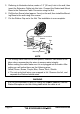
Wall
Gasket
Mounting Bracket
Routing Cable
Cap
Nut
External Speaker Connections
5. Referring to illustration below, make a 1.2” (30 mm) hole in the wall, then
insert the Extension Cable into this hole. Connect the Gasket and Mount
Base to the Extension Cable Connector using the Nut.
6. Drill the four Screw holes (approx. 2 mm) on the wall, then install the Mount-
ing Base to the wall using four screws.
7. Put the Rubber Cap on to the Nut. The installation is now complete.
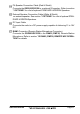
NOTE
The routing cable can be cut and spliced, however care needs to be
taken when reconnecting the wires to ensure water integrity.
Before cutting the cable make sure it is not plugged into the radio. After
cutting you will notice there are the following wires:
Yellow, Green, Brown, Purple, Blue, Green, Red
, Shield
The red and shield wires are wrapped in foil. Remove the foil, and
separate the Red and shield wires.
WARNING
It is not recommended to plug or unplug the RAM3
(
CMP30
)
Remote
Station Microphone into the routing cable while the radio is on.