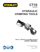
CT10 1650 PSI HYDRAULIC CRIMPING TOOLS Safety, Operation and Maintenance USER’S MANUAL © 2011 Stanley Black & Decker, Inc. New Britain, CT 06053 U.S.A. 58545 3/2014 Ver.
TABLE OF CONTENTS SAFETY SYMBOLS.........................................................................................................................................................4 SAFETY PRECAUTIONS.................................................................................................................................................5 TOOL STICKERS & TAGS............................................................................................................................................
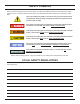
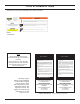
SAFETY SYMBOLS Safety symbols and signal words, as shown below, are used to emphasize all operator, maintenance and repair actions which, if not strictly followed, could result in a life-threatening situation, bodily injury or damage to equipment. This is the safety alert symbol. It is used to alert you to potential personal injury hazards. Obey all safety messages that follow this symbol to avoid possible injury or death.
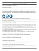
SAFETY PRECAUTIONS Tool operators and maintenance personnel must always comply with the safety precautions given in this manual and on the stickers and tags attached to the tool and hose. These safety precautions are given for your safety. Review them carefully before operating the tool and before performing general maintenance or repairs. Supervising personnel should develop additional precautions relating to the specific work area and local safety regulations.
TOOL STICKERS & TAGS Please refer to the Parts List Illustration for location of stickers. 58499 CT10 Sticker NOTE THE INFORMATION LISTED ON THE STICKERS SHOWN, MUST BE LEGIBLE AT ALL TIMES. REPLACE DECALS IF THEY BECOME WORN OR DAMAGED. REPLACEMENTS ARE AVAILABLE FROM YOUR LOCAL STANLEY DISTRIBUTOR. D A N G E R D A N G E R 1. FAILURE TO USE HYDRAULIC HOSE LABELED AND CERTIFIED AS NON-CONDUCTIVE WHEN USING HYDRAULIC TOOLS ON OR NEAR ELECTRICAL LINES MAY RESULT IN DEATH OR SERIOUS INJURY.
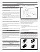
TOOL HOSE INFORMATION HOSE TYPES The rated working pressure of the hydraulic hose must be equal to or higher than the relief valve setting on the hydraulic system.There are three types of hydraulic hose that meet this requirement and are authorized for use with Stanley Hydraulic Tools. They are: Certified non-conductive - constructed of thermoplastic or synthetic rubber inner tube, synthetic fiber braid reinforcement, and weather resistant thermoplastic or synthetic rubber cover.
19-30 19-30 34-45 34-45 34-45 49-60 49-60 5-8 5-8 5-8 9-12 9-12 9-12 13-16 13-16 METERS up to 15 15-30 30-90 up to 15 15-30 30-60 up to 8 8-30 FEET up to 50 51-100 100-300 up to 50 51-100 100-200 up to 25 26-100 Each Hose Length 16 19 19 25.4 16 19 19 25.
HTMA / EHTMA REQUIREMENTS HTMA / EHTMA REQUIREMENTS HTMA HYDRAULIC SYSTEM REQUIREMENTS TYPE I Nominal Operating Pressure (at the power supply outlet) 4-6 gpm (15-23 lpm) 1500 psi (103 bar) TOOL TYPE TYPE II TYPE RR 7-9 gpm (26-34 lpm) 1500 psi (103 bar) 9-10.
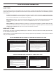
OPERATION TO CHANGE THE CURRENT SETTING: PRE-OPERATION Careful inspection of the tool and hydraulic system before startup is important for safe, reliable operation of the tool. Cylinder Open-Center (no gap) The following items should be checked daily at the start and the end of each work shift. 1. Make sure the proper dies are securely in place. Operating the tool without dies can deform the crimping heads. Refer to Die Installation for instructions. 2. Connect hoses.
OPERATION To install dies, follow the instructions below for your model of crimping head. TO INSTALL DIES ON KEARNEY CRIMPING HEAD -WH3 STYLE: 1. If the hydraulic hoses are connected: Install the die to the C-Frame: • Turn the hydraulic system control valve OFF. • Disconnect first the hydraulic input (supply) hose, then the output (return) hose. 1. Loosen the capscrew at the side of the C-frame. 2. Press the stub on the die into the socket. 2.
OPERATION 2. Connect the tool to an appropriate hydraulic power source. Follow the Hydraulic Hose Connection safety guidelines and instructions in this section. If possible, use the hydraulic power source you plan to use for crimping. The hydraulic fluid temperature should be at least 80°F/27°C for this test. 3. Place the die load tester between the blank (test) dies. 1. Wipe all hose couplers with a clean, lint-free cloth before making connections. 4.
OPERATION 2. Remove any trapped air from the tool by squeezing the trigger 4 or 5 times to advance and retract the piston nearly a full stroke. 3. Position the tool to make the crimp. STORAGE Replace any damaged or missing safety labels and tags before storing the tool. Clean, dry and lubricate moving parts before storage. Store in a clean, dry place. IMPORTANT Failure to center the connector between the dies will damage the dies and/or die holders. 4.
EQUIPMENT PROTECTION & CARE NOTICE In addition to the Safety Precautions in this manual, observe the following for equipment protection and care. • Make sure all couplers are wiped clean before connection. • The hydraulic circuit control valve must be in the “OFF” position when coupling or uncoupling hydraulic tools. Failure to do so may result in damage to the quick couplers and cause overheating of the hydraulic system. • Always store the tool in a clean dry space, safe from damage or pilferage.
TROUBLESHOOTING If symptoms of poor performance develop, the following chart can be used as a guide to correct the problem. When diagnosing faults in operation of the grinder, always check that the hydraulic power source is supplying the correct hydraulic flow and pressure to the grinder as listed in the table. Use a flowmeter known to be accurate. Check the flow with the hydraulic oil temperature at least 80°F/27°C. PROBLEM Tool does not operate. CAUSE SOLUTION Hydraulic hoses not connected properly.
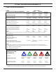
SPECIFICATIONS Capacity (depending on model)..........................................................................500 MCM Copper to 1033 MCM Aluminum Crimping Force..................................................................................................... 12 tons @ 1650 psi / 10,886 kg @ 114 bar Pressure Range............................................................................................................................1650-2500 psi/114-172 bar Flow Range...........................
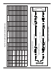
CT10016N PARTS ILLUSTRATION 38A 20A 17 14 19A 15A THIS IS A OLDER MODEL CYLINDER HEAD AND C-FRAME. THE CYLINDER HEAD (ITEM 38A) HAS A THREAD DIAMETER OF 2-3/16 AND A THREAD LENGTH OF 1.100. CHECK THESE DIMENSIONS ON YOUR CYLINDER HEAD BEFORE ORDERING PARTS TO MAKE SURE YOU ARE ORDERING THE CORRECT PARTS. 39 THIS IS A NEWER MODEL CYLINDER HEAD AND C-FRAME. THE CYLINDER HEAD (ITEM 38) HAS A THREAD DIAMETER OF M60X1.5 (METRIC) AND A THREAD LENGTH OF 1.100.
CT10016N PARTS LIST Item No. Part No. Retaining Ring 36 58485 1 O-Ring 14 HSHCS 37 58493 1 Cylinder 07626 2 O-Ring 38 67276 1 Cylinder Head * 4 09330 1 O-Ring 38A 58494 1 Cylinder Head ** 5 00294 1 O-Ring 39 58499 1 Sticker 6 00360 1 O-Ring 40 58583 1 T-Seal 58594 1 Retaining Ring Item No. Part No.
CT10056DN & DH PARTS ILLUSTRATION üüüüüüüüüüüüüüüüüüüü C-FRAME. THE CYLINDER HEAD (ITEM 38A) HAS A THREAD DIAMETER OF 2-1/8 AND A THREAD LENGTH OF 1.650. CHECK THESE DIMENSIONS ON üüüüüüüüüüüüüüüüüüüü TO MAKE SURE YOU ARE ORDERING THE CORRECT PARTS. 16 22A 24A 23A 38A 25A üüüüüüüüüüüüüüüüüüüü C-FRAME. THE CYLINDER HEAD (ITEM 38) HAS A THREAD DIAMETER OF M60X1.5 (METRIC) AND A THREAD LENGTH OF 1.100.
CT10056DN & DH PARTS LIST Item No. Part No.
CT10056N PARTS ILLUSTRATION 21
CT10056N PARTS LIST Item No. Part No. Qty 1 00118 1 2 00144 3 4 Description Item No. Part No.
CT10066AN PARTS ILLUSTRATION 17 20A 41A 3A 18 15 43 45 This is an older model cylinder head and c-frame. The cylinder head (item 41A) has a threaded diameter of 2-3/8 and a thread length of 1.500. Check these dimensions on your cylinder head before ordering parts to make sure you are ordering correct parts. 44 46 47 40 This is a newer model cylinder head and c-frame. The cylinder head (item 41) has a threaded diameter of M60x1.5 (metric) and a thread length of 1.100.
CT10066AN PARTS LIST Item No. Part No.
Stanely Hydraulic Tools 3810 SE Naef Road Milwaukie, Oregon 503-659-5660 / Fax 503-652-1780 www.stanleyhydraulic.