BR40 HYDRAULIC BREAKER Safety, Operation and Maintenance USER MANUAL © 2011 Stanley Black & Decker, Inc. New Britain, CT 06053 U.S.A. 62399 2/2011 Ver.
DECLARATION OF CONFORMITY DECLARATION OF CONFORMITY ÜBEREINSTIMMUNGS-ERKLARUNG DECLARATION DE CONFORMITE CEE DECLARACION DE CONFORMIDAD DICHIARAzIONE DI CONFORMITA Hydraulic Tools ______________________________________________________________________ I, the undersigned: Ich, der Unterzeichnende: Je soussigné: El abajo firmante: lo sottoscritto: Weisbeck, Andy Surname and First names/Familiennname und Vornamen/Nom et prénom/Nombre y apellido/Cognome e nome hereby declare that the equipment specified here
TABLE OF CONTENTS DECLARATION OF CONFORMITY...........................................................................................................................2 safety SYMBOLS...................................................................................................................................................4 SAFETY PRECAUTIONS...........................................................................................................................................5 TOOL STICKERS & TAGS..
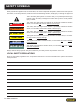
safety SYMBOLS Safety symbols and signal words, as shown below, are used to emphasize all operator, maintenance and repair actions which, if not strictly followed, could result in a life-threatening situation, bodily injury or damage to equipment. This is the safety alert symbol. It is used to alert you to potential personal injury hazards. Obey all safety messages that follow this symbol to avoid possible injury or death.
SAFETY PRECAUTIONS Tool operators and maintenance personnel must always comply with the safety precautions given in this manual and on the stickers and tags attached to the tool and hose. These safety precautions are given for your safety. Review them carefully before operating the tool and before performing general maintenance or repairs. Supervising personnel should develop additional precautions relating to the specific work area and local safety regulations.
Safety PRECAUTIONS • Warning: Hydraulic fluid under pressure could cause skin injection injury. If you are injured by hydraulic fluid, get medical attention immediately. • Never use the tool in an explosive atmosphere, sparks from the breaking process could ignite explosive gas. • Keep all body parts away from the working tool. • • Always wear personal protection equipment (PPE) such as goggles, safety shoes, head, eye, breathing, and ear protection when operating the tool.
TOOL STICKERS & TAGS Stanley Hydraulic tools division of the Stanley Works 3810 SE Naef Road Milwaukie, OR 97267 05152 Stanley Decal 28374 Name Tag (BR40568YA) 12835 Name Tag (BR40550) 71072 CE Tool Plate 58601 Sound Level Decal (CE Tool only) 28409 Composite Decal (CE Tool only) 11206 Circuit Type C Decal (CE Tool only) NOTE: THE INFORMATION LISTED ON THE STICKERS SHOWN, MUST BE LEGIBLE AT ALL TIMES. REPLACE DECALS IF THEY BECOME WORN OR DAMAGED.
HOSE TYPES The rated working pressure of the hydraulic hose must be equal to or higher than the relief valve setting on the hydraulic system. There are three types of hydraulic hose that meet this requirement and are authorized for use with Stanley Hydraulic Tools. They are: Certified non-conductive — constructed of thermoplastic or synthetic rubber inner tube, synthetic fiber braid reinforcement, and weather resistant thermoplastic or synthetic rubber cover.
All hydraulic hose must meet or exceed specifications as set forth by SAE J517. All hydraulic hose must have at least a rated minimum working pressure equal to the maximum hydraulic system relief valve setting. This chart is intended to be used for hydraulic tool applications only based on Stanley Hydraulic Tools tool operating requirements and should not be used for any other applications.
HTMA REQUIREMENTS TOOL CATEGORY HYDRAULIC SYSTEM REQUIREMENTS TYPE I TYPE II TYPE III TYPE RR Flow Rate 4–6 gpm (15–23 lpm) 7–9 gpm (26–34 lpm) 11–13 gpm (42–49 lpm) 9–10.
OPERATION The recommended hose size is .500 inch/12 mm I.D. up to 50 ft/15 m long and .625 inch/16 mm I.D. minimum up to 100 ft/30 m. Pre-Operation Procedures NOTE: Partially depressing the trigger allows the tool to run at slow speed. Slow-speed operation permits easier starting of the tool bit into the work surface. 1. Using a calibrated flowmeter and pressure gauge, check that the hydraulic power source develops a flow of 4–6 gpm/15–23 lpm at 1300 psi/90 bar. 5.
TOOL PROTECTION & CARE NOTICE In addition to the Safety Precautions found in this manual, observe the following for equipment protection and care. • Make sure all couplers are wiped clean before connection. • Always keep critical tool markings, such as warning stickers and tags legible. • The hydraulic circuit control valve must be in the OFF position when coupling or uncoupling hydraulic tools. Failure to do so may result in damage to the quick couplers and cause overheating of the hydraulic system.
TROUBLESHOOTING PROBLEM Tool does not run. CAUSE REMEDY Power unit not functioning. Check power unit for proper flow and pressure (4–6 gpm/15–23 lpm, 1300– 2000 psi/90–140 bar. Couplers or hoses blocked. Remove restriction. Pressure and return line hoses reversed at ports. Be sure hoses are connected to their proper ports. Mechanical failure of piston or automatic valve. Disassemble breaker and inspect for damaged parts. Power unit not functioning.
CHARGING THE ACCUMULATOR Accumulator Testing Procedure To check or charge the accumulator the following equipment is required: • 31254 Charge Kit: which includes the following. –– Accumulator Tester (Part Number 02835). –– Charging Assembly (P/N 15304, includes a liquid filled gauge with snub valve, hose and fittings). • NITROGEN bottle with an 800 psi/55 bar minimum charge.(Not included in 31254 kit) Accumulator Charging 1. Perform Steps 1 through 4 of the accumulator testing procedure above. 2.
CHARGING THE ACCUMULATOR Charging the Accumulator (BR40 with Anti-Vibration Handles) CW TESTER CHARGING VALVE CHUCK GAUGE ACCUMULATOR TESTER ( P/N 02835 ) LOCATION OF CHARGING VALVE Figure 2 Figure 2.
SPECIFICATIONS Pressure Range................................................................................................................ 1300–2000 psi/90–140 bar Flow Range.................................................................................................................................. 4–6 gpm/15–23 lpm Optimum Flow........................................................................................................................................ 5 gpm/20 lpm Maximum Back Pressure...
BR40 T-HANDLE PARTS ILLUSTRATION BR40 User Manual ◄ 17
BR40 T-HANDLE Parts LIST Item Part No. Qty Description Item Part No. Qty Description 1 03971 1 Coupler Set 47 04780 1 Back-Up Washer 2 — — No Item 48 04386 4 Cup Seal 3 02900 2 Roll Pin 49 04373 1 Side Rod 4 01652 2 Alternate Hose Assy. – 12 inch.
BR40 PARTS br40 ANTI-VIBRATION HANDLE PARTS ILLUSTRATION BR40 User Manual ◄ 19
BR40 Parts LIST br40 ANTI-VIBRATION HANDLE PARTS LIST Item Part No. Qty Description Item Part No.
Stanley Hydraulic Tools 3810 SE Naef Road Milwaukie, Oregon 503-659-5660 / Fax 503-652-1780 www.stanleyhydraulic.com IMPORTANT To fill out a Product Warranty Recording form, and for information on your warranty, visit Stanleyhydraulic.com and select the Warranty tab. (Note: the warranty recording form must be submitted to validate the warranty).