TT46 HYDRAULIC TIE TAMPER USER MANUAL Safety, Operation and Maintenance © 2012 Stanley Black & Decker, Inc. New Britain, CT 06053 U.S.A.
DECLARATION OF CONFORMITY DECLARATION OF CONFORMITY ÜBEREINSTIMMUNGS-ERKLARUNG DECLARATION DE CONFORMITE CEE DECLARACION DE CONFORMIDAD DICHIARAZIONE DI CONFORMITA Hydraulic Tools ______________________________________________________________________ I, the undersigned: Ich, der Unterzeichnende: Je soussigné: El abajo firmante: lo sottoscritto: Weisbeck, Andy Surname and First names/Familiennname und Vornamen/Nom et prénom/Nombre y apellido/Cognome e nome hereby declare that the equipment specified here
TABLE OF CONTENTS DECLARATION OF CONFORMITY...........................................................................................................................2 SAFETY SYMBOLS....................................................................................................................................................4 SAFETY PRECAUTIONS...........................................................................................................................................5 TOOL STICKERS & TAGS.
SAFETY SYMBOLS Safety symbols and signal words, as shown below, are used to emphasize all operator, maintenance and repair actions which, if not strictly followed, could result in a life-threatening situation, bodily injury or damage to equipment. This is the safety alert symbol. It is used to alert you to potential personal injury hazards. Obey all safety messages that follow this symbol to avoid possible injury or death.
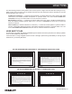
SAFETY PRECAUTIONS Tool operators and maintenance personnel must always comply with the safety precautions given in this manual and on the stickers and tags attached to the tool and hose. These safety precautions are given for your safety. Review them carefully before operating the tool and before performing general maintenance or repairs. Supervising personnel should develop additional precautions relating to the specific work area and local safety regulations.
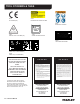
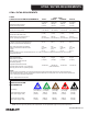
TOOL STICKERS & TAGS 28322 CE STICKER (CE) 25610 RAILROAD HELP DESK STICKER Lwa 28409 COMPOSITE STICKER 107 11206 CIRCUIT TYPE C STICKER (CE) 17784 SOUND POWER STICKER 07589 CAUTION/GPM STICKER 23230 NAME TAG (4-6 GPM MODELS) 65049 NAME TAG (10 GPM MODEL) NOTE: THE INFORMATION LISTED ON THE STICKERS SHOWN, MUST BE LEGIBLE AT ALL TIMES. REPLACE DECALS IF THEY BECOME WORN OR DAMAGED. REPLACEMENTS ARE AVAILABLE FROM YOUR LOCAL STANLEY DISTRIBUTOR.
HOSE TYPES The rated working pressure of the hydraulic hose must be equal to or higher than the relief valve setting on the hydraulic system. There are three types of hydraulic hose that meet this requirement and are authorized for use with Stanley Hydraulic Tools. They are: Certified non-conductive — constructed of thermoplastic or synthetic rubber inner tube, synthetic fiber braid reinforcement, and weather resistant thermoplastic or synthetic rubber cover.
► TT46 User Manual All hydraulic hose must meet or exceed specifications as set forth by SAE J517. All hydraulic hose must have at least a rated minimum working pressure equal to the maximum hydraulic system relief valve setting. This chart is intended to be used for hydraulic tool applications only based on Stanley Hydraulic Tools tool operating requirements and should not be used for any other applications.
HTMA / EHTMA REQUIREMENTS HTMA / EHTMA REQUIREMENTS HTMA HYDRAULIC SYSTEM REQUIREMENTS TYPE I Nominal Operating Pressure (at the power supply outlet) 4-6 gpm (15-23 lpm) 1500 psi (103 bar) TOOL TYPE TYPE II TYPE RR 7-9 gpm (26-34 lpm) 1500 psi (103 bar) 9-10.
OPERATION PREOPERATION PROCEDURES making connections. CHECK HYDRAULIC POWER SOURCE 2. Connect the hoses from the hydraulic power source to the tool fitting or quick disconnects. It is a good practice to connect the return hose first and disconnect it last to minimize or avoid trapped pressure within the tool. 1. Using a calibrated flowmeter and pressure gauge, check that the hydraulic power source develops a flow of 4-6 gpm/15-23 lpm at 1500-2000 psi/106-140 bar. For TT46233 Model, 7-10 gpm/26-38 lpm.
TOOL PROTECTION & CARE NOTICE In addition to the Safety Precautions found in this manual, observe the following for equipment protection and care. • Make sure all couplers are wiped clean before connection. • The hydraulic circuit control valve must be in the “OFF” position when coupling or uncoupling hydraulic tools. Failure to do so may result in damage to the quick couplers and cause overheating of the hydraulic system. • Always store the tool in a clean dry space, safe from damage or pilferage.
TROUBLESHOOTING If symptoms of poor performance develop, the following chart can be used as a guide to correct the problem. When diagnosing faults in operation of the wrench, always check that the hydraulic power source is supplying the correct hydraulic flow and pressure to the tool as listed in the following table. Use a flow meter known to be accurate. Check the flow with the hydraulic fluid temperature at least 80o F/27o C. SYMPTOM CAUSE SOLUTION Tie tamper does not run. Power unit not functioning.
CHARGING THE ACCUMULATOR CHARGING THE ACCUMULATOR To check or charge the accumulator the following equipment is required: • Accumulator tester (Part Number 02835). • Charging assembly (Part Number 15304) (includes a guage w/snub valve, hose and fitting). • NITROGEN bottle with a 800 psi/56 bar minimum charge. 1. On charge valves containing 5/8 inch hex locking nuts, first loosen the locking nut 1-1/2 turns. 2.
CHARGING THE ACCUMULATOR Charge Location TT46113, TT46113C, TT46133, TT46133B, TT46133C, TT46133UP Charging theonAccumulator (BR 45 with Anti-Vibration Handles)and TT46233 CW TESTER CHARGING VALVE CHUCK GAUGE LOCATION OF CHARGING VALVE ACCUMULATOR TESTER ( P/N 02835 ) Figure 2 Liquid Filled Gauge w/Snub Valve Charge Fitting Nitrogen Tank (Not included in Kit) Charging Valve 31254 ACCUMULATOR CHARGE KIT Includes: Liquid Filled Gauge w/Snub Valve, Hose, Charge Fitting, 02835 Tester, and Box (not pic
SPECIFICATIONS SPECIFICATIONS Pressure Range........................................................................................................................1500-2000 psi /106-140 bar Maximum Back Pressure............................................................................................................................. 200 psi / 14 bar Flow Range ..........................................................................................................................................
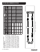
TT46113/133/233 PARTS ILLUSTRATION TT46113/TT46113C Use Lower End Assy Shown Below.
TT46113/133/233 PARTS LIST Item 1 2 3 4 5 6 7 8 9 10 11 12 13 14 15 16 17 18 19 20 21 22 23 24 25 26 27 Part No.
TT46112 PARTS ILLUSTRATION 18 ► TT46 User Manual
TT46112 PARTS LIST Item 1 2 3 4 5 6 7 8 9 10 11 12 13 14 15 16 17 18 19 20 21 22 23 24 25 26 27 28 29 30 31 32 33 34 35 36 37 38 39 40 41 42 43 Part No.
Stanley Hydraulic Tools 3810 SE Naef Road Milwaukie, Oregon 97267-5698 USA (503) 659-5660 / Fax (503) 652-1780 www.stanleyhydraulics.