BR89 Hydraulic breaker Safety, Operation and Maintenance USER MANUAL © 2011 Stanley Black & Decker, Inc. New Britain, CT 06053 U.S.A. 70063 2/2011 Ver.
Table of contents Safety symbols...................................................................................................................................................4 Safety Precautions...........................................................................................................................................5 Tool stickers & tags.........................................................................................................................................7 Hose types...
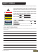
Safety symbols Safety symbols and signal words, as shown below, are used to emphasize all operator, maintenance and repair actions which, if not strictly followed, could result in a life-threatening situation, bodily injury or damage to equipment. This is the safety alert symbol. It is used to alert you to potential personal injury hazards. Obey all safety messages that follow this symbol to avoid possible injury or death.
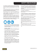
Safety Precautions Tool operators and maintenance personnel must always comply with the safety precautions given in this manual and on the stickers and tags attached to the tool and hose. These safety precautions are given for your safety. Review them carefully before operating the tool and before performing general maintenance or repairs. Supervising personnel should develop additional precautions relating to the specific work area and local safety regulations.
Safety Precautions • Warning: Hydraulic fluid under pressure could cause skin injection injury. If you are injured by hydraulic fluid, get medical attention immediately. • Keep all body parts away from the working tool. • When handling material or the tool bit, wear your (PPE) Personal Protection Equipment. • Be observant of the hydraulic hoses lying about the work area, they can be a tripping hazard. • Always de-energize the hydraulic system when changing a tool bit.
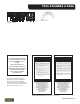
Tool stickers & tags 10180 Caution Decal 13842 BR89 Name Decal NOTE: THE INFORMATION LISTED ON THE STICKERS SHOWN, MUST BE LEGIBLE AT ALL TIMES. REPLACE DECALS IF THEY BECOME WORN OR DAMAGED. REPLACEMENTS ARE AVAILABLE FROM YOUR LOCAL STANLEY DISTRIBUTOR. The safety tag (p/n 15875) at right is attached to the tool when shipped from the factory. Read and understand the safety instructions listed on this tag before removal. We suggest you retain this tag and attach it to the tool when not in use.
Hose types The rated working pressure of the hydraulic hose must be equal to or higher than the relief valve setting on the hydraulic system. There are three types of hydraulic hose that meet this requirement and are authorized for use with Stanley Hydraulic Tools. They are: Certified non-conductive — constructed of thermoplastic or synthetic rubber inner tube, synthetic fiber braid reinforcement, and weather resistant thermoplastic or synthetic rubber cover.
All hydraulic hose must meet or exceed specifications as set forth by SAE J517. All hydraulic hose must have at least a rated minimum working pressure equal to the maximum hydraulic system relief valve setting. This chart is intended to be used for hydraulic tool applications only based on Stanley Hydraulic Tools tool operating requirements and should not be used for any other applications.
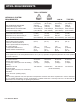
Htma requirements TOOL CATEGORY HYDRAULIC SYSTEM REQUIREMENTS TYPE I TYPE II TYPE III TYPE RR Flow Rate 4–6 gpm (15–23 lpm) 7–9 gpm (26–34 lpm) 11–13 gpm (42–49 lpm) 9–10.
Operation The recommended hose size is .500 inch/12 mm ID up to 50 ft/15 m long and .625 inch/16 mm ID minimum up to 100 ft/30 m. Pre-Operation Procedures Check Power Source 1. Using a calibrated flowmeter and pressure gauge, check that the hydraulic power source develops a flow of 7–9 gpm/26–34 lpm at 1500–2000 psi/105– 140 bar. 2. Make certain the hydraulic power source is equipped with a relief valve set to open at 2100–2250 psi/145– 155 bar maximum. Install Tool Bit 1.
Tool protection & care NOTICE In addition to the Safety Precautions found in this manual, observe the following for equipment protection and care. • Make sure all couplers are wiped clean before connection. • Do not force a small breaker to do the job of a large breaker. • The hydraulic circuit control valve must be in the OFF position when coupling or uncoupling hydraulic tools. Failure to do so may result in damage to the quick couples and cause overheating of the hydraulic system.
troubleshooting PROBLEM Tool does not run. CAUSE Solution Power unit not functioning. Check power unit for proper flow and pressure (7–9 gpm/26–34 lpm, 1500– 2000 psi/105–140 bar. Couplers or hoses blocked. Remove restriction. Pressure and return line hoses reversed at ports. Be sure hoses are connected to their proper ports. Mechanical failure of piston or automatic valve. Disassemble breaker and inspect for damaged parts. Power unit not functioning.
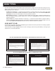
Charging the accumulator Accumulator Testing Procedure To check or charge the accumulator the following equipment is required: • 31254 Charge Kit: which includes the following. –– Accumulator Tester (Part Number 02835). –– Charging Assembly (P/N 15304— includes a liquid filled gauge with snub valve, hose and fittings.) • and connect the charging assembly chuck directly to the charging valve. 3. Adjust the regulator to the charging pressure of 800 psi/55 bar.
Charging the accumulator Liquid filled gauge with snub valve Nitrogen tank not included in kit Charge fitting 02835 Tester 15304 Accumulator Charge Assy, (includes liquid filled gauge with snub valve, hose and charge fitting) 31254 Accumulator Charge Kit (includes everything pictured, except nitrogen tank and includes a 372047 box) Figure 2.
Specifications Pressure Range.............................................................................................................. 1500–2000 psi/105–140 bar Flow Range.................................................................................................................................. 7–9 gpm/26–34 lpm Optimum Flow........................................................................................................................................ 8 gpm/30 lpm Maximum Back Pressure....
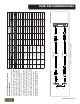
br89 parts illustration BR89 User Manual ◄ 17
BR89 parts list Item Part No. Qty Description Item Part No.
Stanley Hydraulic Tools 3810 SE Naef Road Milwaukie, Oregon 503-659-5660 / Fax 503-652-1780 www.stanleyhydraulic.com IMPORTANT To fill out a Product Warranty Recording form, and for information on your warranty, visit Stanleyhydraulic.com and select the Warranty tab. (Note: the warranty recording form must be submitted to validate the warranty).