B.A.S.I.S.
Copyright © 2004 Stanley Security Solutions, Inc. and Stanley Logistics, Inc. All rights reserved. Printed in the United States of America. Information in this document is subject to change without notice and does not represent a commitment on the part of Stanley Security Solutions, Inc. The software described in this document are furnished under a license agreement or nondisclosure agreement.
FCC Compliance Statement Note: This equipment has been tested and found to comply with the limits for a Class B digital device, pursuant to part 15 of the FCC Rules. These limits are designed to provide reasonable protection against harmful interference in a residential installation. This equipment generates, uses and can radiate radio frequency energy and, if not installed and used in accordance with the instructions, may cause harmful interference to radio communications.
Contents 1 Introduction Related documents 1–1 Getting technical support 1–2 How to use this guide 1–2 2 Architectural overview B.A.S.I.S. online and offline diagram 2–3 How B.A.S.I.S. G ‘Guest’ locks work 2–4 Components and connections 2–6 Feature comparison of B.A.S.I.S. G and B.A.S.I.S. V 2–7 Setup overview 2–10 3 First-time B.A.S.I.S.
4 Setting up and Maintaining B.A.S.I.S.® Offline Locks Introducing B.A.S.I.S. Transport 4–1 Programming locks 4–2 Retrieving history records 4–11 Using diagnostics features 4–14 5 Managing B.A.S.I.S.
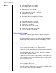
C h a p t e r 1 Introduction Thank you for choosing B.A.S.I.S.® G and V, the world’s leading combination online and offline access control system. Use this guide to make sure that you set up your system in the most efficient way and to get the most out of it. The initial setup of the B.A.S.I.S. G & V system is not trivial, but if done thoroughly it will pay many dividends. Related documents The following documents are available to help you install, maintain, or operate other related systems.
Chapter 1: Introduction Notes ■ ■ ■ ■ ■ ■ ■ ■ ■ ■ ■ ■ ■ ■ ■ ■ ■ ■ ID CredentialCenter User Guide Basic Import Utility User Guide Installation & Setup User Guide MapDesigner™ User Guide System Administration User Guide Universal Interface Server User Guide Replicator User Guide View/Edit Only Workstation User Guide Alternative Wiring Configurations Guide Legato® Co-StandbyServer™ User Guide Hardware Installation Guide Visitor Management User Guide Area Access Manager User Guide Digital Video User Guide Vi
Chapter 1: Introduction Appendix A, Glossary – This appendix provides a list of terms that are specifically used in the B.A.S.I.S. software. Terms that appear in the glossary are set in italics when they are first used.
Chapter 1: Introduction 1–4
C h a p t e r 2 Architectural overview This chapter describes the ‘big picture’ of the online B.A.S.I.S.® access control system world and how the offline B.A.S.I.S. G and V product fits into that world. The B.A.S.I.S. product line is composed of two general architectural models used to address the security needs of most customer requirements and applications. These two models can be generally categorized as online and offline.
Chapter 2: Architectural overview This configuration is accomplished through an operator entering data on or through a computer called a server. In the world of B.A.S.I.S. this server is a computer where the access control system database resides. An operator can enter configurations in the server database through a B.A.S.I.S. application that resides on the server or through one of many possible B.A.S.I.S. workstations that exist on the access control network.
Chapter 2: Architectural overview B.A.S.I.S. online and offline diagram Notes The B.A.S.I.S. system is capable of being configured as both an online and an offline access control system. This means that with B.A.S.I.S. you can manage readers, locks, controllers, in fact, any access control hardware, whether or not they are wired directly to a panel or not. This diagram describes a typical combined online and offline B.A.S.I.S. system. Figure 2.1 B.A.S.I.S.
Chapter 2: Architectural overview Notes How B.A.S.I.S. G ‘Guest’ locks work B.A.S.I.S. G offline locks are designed primarily for the college and university dormitory. But they can be effectively used in any application where a room has continuous occupancy change over a period of time, or where the lock location is remote or isolated enough that going out to reprogram the lock becomes undesirable.
Chapter 2: Architectural overview Figure 2.2 1001 issue code: 01 1001 issue code: 00 Lost card Notes Guest functionality diagrammed Issue codes 00 01 02 03 Newly encoded card Issue codes offset of 1 range of 3 valid issue codes 01 02 03 04 lost card does not work new offset new range Auto update B.A.S.I.S. G Lock Same B.A.S.I.S.
Chapter 2: Architectural overview Notes Figure 2.3 1001 issue code: 00 1001 issue code: 99 Lost card Guest functionality in rollover diagrammed Issue codes 00 01 02 Newly encoded card offset of 1 range of 3 valid issue codes Issue codes 00 01 02 03 new offset new range lost card does not work Auto update B.A.S.I.S. G Lock Same B.A.S.I.S.
Chapter 2: Architectural overview Feature comparison of B.A.S.I.S. G and B.A.S.I.S. V Notes The differences between B.A.S.I.S. G and B.A.S.I.S. V can be confusing since they share many of the same features. The following table compares the two systems side by side. B.A.S.I.S. Feature Description G V Guest (dormitory feature Provides the ability to issue pre-created badge ID's to students. This supports the assignment of one reader directly to the badge.
Chapter 2: Architectural overview Notes B.A.S.I.S. Feature Description G V Denied attempts Includes attempts count and time out duration. Sometimes referred to as ‘Three strikes your out.’ Logging (grant, denies, status) Provides the ability to filter the displaying/ logging of history events. This feature is implemented at the Management System level. ■ ■ always logged configurable Daylight saving time Support for all OS world time zones.
Chapter 2: Architectural overview Notes B.A.S.I.S. Feature Description G V Cycle count/ reset The lockset will maintain a current count of access grants. The count can be reset by the user. ■ ■ DIagnostics code This code provides some feedback of the lockset's status. ■ ■ Backup battery level Displays the current level of the backup battery. ■ ■ Displays the current level of the main electronics battery. ■ ■ This feature allows for the unlocking of the door for the unlock duration.
Chapter 2: Architectural overview Notes Setup overview In the next chapter you will find complete step-by-step instructions on the first-time configuration of a B.A.S.I.S.® offline system. But listed here are the major steps of that process and cross-references where you can find each corresponding task. Task 1 Install the system components. This task begins on page 3-2. B.A.S.I.S. Software, see page 3-2. ■ Encoder, see page 3-3. ■ PDA, see page 3-5. ■ B.A.S.I.S. Transport, see page 3-6.
C h a p t e r 3 First-time B.A.S.I.S.® Offline System Configuration You are now ready to start setting up your B.A.S.I.S.® offline system. The following tasks do not include the installation of the locks themselves. The installation of the B.A.S.I.S. G or B.A.S.I.S. V locks are fully described in the following installation instruction documents.
Chapter 3: First-time B.A.S.I.S.® Offline System Configuration Make sure that the B.A.S.I.S. G or V locks are at least on site and ready to be programmed. Locks may be programmed before installation. Notes Installing the system Make sure that you have the following components before you start installing the B.A.S.I.S. Offline system: ■ ■ ■ ■ ■ B.A.S.I.S. software, version 5.8, build 41b or higher Dedicated computer, see your BEST representative for complete details. Personal digital assistant (PDA).
Chapter 3: First-time B.A.S.I.S.® Offline System Configuration Installing the encoder Notes Two types of encoders are available for the B.A.S.I.S. Offline system: Magnetic stripe encoder Unitech model MSR206 part number MSR206-33 ■ Smart card encoder GemPlus model GEMPC410 part number GCR410-P BEST part number 1825235 ■ For proper setup of the smart card encoder, contact your BEST Representative.
Chapter 3: First-time B.A.S.I.S.® Offline System Configuration 10 Click Add. Notes Figure 3.1 Configuring the encoder Click to test whether the encoder is online 11 Under Encoder Settings, in the name field, type a name for the encoder. 12 In the Encoder Type field, select: Magstripe Swipe Reader/Writer (Model 712 or 722) 13 Click Test. Note The encoder can be tested at any time by returning to the Encoder tab. You do not need to put the encoder in modify mode to test the encoder. 14 Click OK.
Chapter 3: First-time B.A.S.I.S.® Offline System Configuration Installing the PDA Notes The Personal Digital Assistant (PDA) is your link from the B.A.S.I.S. workstation to the B.A.S.I.S. G and V lock. With the help of your computer network administrator, if necessary, perform the following steps to set up the connection between the PDA and the B.A.S.I.S. workstation. To install Microsoft ActiveSync 1 Connect the PDA to the B.A.S.I.S. workstation. 2 Install Microsoft ActiveSync.
Chapter 3: First-time B.A.S.I.S.® Offline System Configuration Installing B.A.S.I.S. Transport Notes Confirm that the following requirements are met for running B.A.S.I.S. Transport. For detailed instructions see the B.A.S.I.S. Installation & Configuration User Guide. B.A.S.I.S. System Administration is installed. B.A.S.I.S. Communication Server is installed. Microsoft ActiveSync is installed. A connection is established between the PDA and the PC using ActiveSync. Note Before you can install B.
Chapter 3: First-time B.A.S.I.S.® Offline System Configuration Defining the system Notes Overview To define a B.A.S.I.S.® G or B.A.S.I.S. V system, you need to configure: Card formats Badge types ‘Virtual’ offline access panels Guest readers Although B.A.S.I.S. locks are offline (stand-alone) and are not managed by access control panels, you must define Access Panel settings for the locks. In effect, you define ‘virtual’ access control panels for the locks.
Chapter 3: First-time B.A.S.I.S.® Offline System Configuration Notes Choose the appropriate card format 3 Choose the appropriate card format and click OK. The modify card format window displays Figure 3.2 Defining card formats When the guest format check box is selected, the data is offset from the start of the card by the fact that the activation and deactivation dates are encoded onto the card. Set the access control track to 3.
Chapter 3: First-time B.A.S.I.S.® Offline System Configuration 4 Type the name of the card format. A typical name for the guest format is ‘Guest format.’ 5 Complete all appropriate fields including facility code, access control track, total characters on track, and the guest format check box. Defining badge types To use B.A.S.I.S. G functionality, you must define a guest badge type. This badge type allows you to define and allocate a range of badge ID numbers that will be programmed into the lock.
Chapter 3: First-time B.A.S.I.S.® Offline System Configuration To define a guest badge type Notes 1 From System Administration, click Administration > Badge Types. The Badge Types form displays 2 Click Add. The modify badge type window displays Figure 3.3 type Selecting the Guest class for B.A.S.I.S. G badge Choosing the Guest classification enables the features of the Badge ID Allocation tab. 3 Select the Guest class from the drop down box. 4 Complete all other necessary information on the tab.
Chapter 3: First-time B.A.S.I.S.® Offline System Configuration Notes Figure 3.4 Making sure that the Guest Card format is selected for printing and encoding Make sure that the Guest format is selected for encoding Guest Badge Types. 6 Select the appropriate card format to be encoded for the badge type. 7 Make sure that a check mark appears next to the selected card format. 8 Click the Badge ID Allocation tab.
Chapter 3: First-time B.A.S.I.S.® Offline System Configuration Notes Figure 3.5 Entering the range of Badge IDs Enter the appropriate range of badge IDs for your application. 9 Enter the First ID number in the badge range that you want to create. Application note Make sure to allocate a range of badge numbers that will facilitate the future growth of a group of locks.
Chapter 3: First-time B.A.S.I.S.® Offline System Configuration Defining ‘virtual’ offline access panels Notes Although B.A.S.I.S. Locks are offline (stand-alone) locks and are not managed by access control panels, you must define Access Panel settings for the locks. In effect, you define ‘virtual’ access control panels for the locks. Using the virtual access panel concept allows the programming of guest locks to follow the same conventions as B.A.S.I.S. online products.
Chapter 3: First-time B.A.S.I.S.® Offline System Configuration Notes Figure 3.6 Naming the offline lock access panel Name the offline lock access panel appropriately for all of the possible 64 locks that it controls. The workstation name refers to the technical name of the computer to which the PDA is attached. 4 In the Name field, type the name of the ‘virtual’ access control panel. 5 Click OK. 6 Repeat steps 3 and 4 as necessary.
Chapter 3: First-time B.A.S.I.S.® Offline System Configuration Defining the Guest reader/lock Notes In the B.A.S.I.S. software locks are referred to as readers to conform and maintain consistency with B.A.S.I.S. online terminology conventions. You can define up to 64 readers or locks for each ‘virtual’ offline access control panel. And each reader or lock will accept up to eight different card formats. It would be highly unusual to use this many formats in one lock.
Chapter 3: First-time B.A.S.I.S.® Offline System Configuration 8 Under the Card Format section, select the Guest Card Format. Notes Application note Selecting the ‘Offline Guest’ reader type refers to a B.A.S.I.S. V configuration. A selection of the Offline reader type is not recommended. 9 Make any other selections as necessary. 10 Click OK. The Reader is listed in the Reader listing at the top of the window. 11 Repeat steps 3 – 10 for each additional lock/reader.
Chapter 3: First-time B.A.S.I.S.® Offline System Configuration To define other guest reader features Notes 1 From System Administration, click Access Control > Readers. 2 Click the Offline tab. 3 Select the Reader that you want to define. Make sure that the check mark is next to the reader to be modified. 4 Click Modify. The Modify Offline Reader window displays Figure 3.
Chapter 3: First-time B.A.S.I.S.® Offline System Configuration 8 In the Guest Parameters section, select whether the lock/ reader will be a Common door. Notes 9 In the Badge Type field, select a guest badge type from the list that was created. See page 3-9. 10 In the Number of badges field, enter the number of guest badges to be allocated to this lock/reader from the total pool of badge IDs.
C h a p t e r 4 Setting up and Maintaining B.A.S.I.S.® Offline Locks This section describes how to use your B.A.S.I.S.® Transport software. The following topics are covered. Introducing B.A.S.I.S. Transport The B.A.S.I.S. Transport software application lets you: program B.A.S.I.S. G and B.A.S.I.S. V Locks by transferring reader configurations from B.A.S.I.S. System Administration to the locks ■ transfer history records from B.A.S.I.S.
Chapter 4: Setting up and Maintaining B.A.S.I.S.® Offline Locks Notes Programming locks To program a B.A.S.I.S. G or B.A.S.I.S. V Lock, you need to: Define an access control panel and reader configuration for the lock using B.A.S.I.S. System Administration. For more information, see page 3-7 of this guide as well as the B.A.S.I.S. System Administration User Guide. Transfer the reader configuration from the PC to the PDA. See the next section.
Chapter 4: Setting up and Maintaining B.A.S.I.S.® Offline Locks Figure 4.1 Notes System Administration System Tree You can expand the entries in the System Tree to see the hierarchy of access control devices in your system. To expand an entry, click the plus sign (+) to the left of the entry. To collapse an entry, click the minus sign (–) to the left of the entry. 5 Expand the Hardware entry to view the access control panels defined for your system.
Chapter 4: Setting up and Maintaining B.A.S.I.S.® Offline Locks To highlight multiple readers, hold down the Ctrl key and click each reader. Notes 7 Right-click on the selection in the System Tree. The menu shown in Figure 4.3 appears. Figure 4.3 Right mouse button menu for readers in the System Tree Use the right mouse button on any reader to display this menu. 8 Click Download. The PC begins transferring the highlighted reader configurations to the PDA.
Chapter 4: Setting up and Maintaining B.A.S.I.S.® Offline Locks Transferring a configuration from the PDA to a lock The sections below provide instructions for sending a panel/ reader configuration to a B.A.S.I.S. G or B.A.S.I.S. V Lock. To connect the PDA to a lock See Figure 4.4 and perform these steps: Figure 4.4 Connecting the PDA to a lock PDA Serial cable Communication port Programming cable 1 Connect the serial cable to the PDA. 2 Connect the serial cable to the programming cable.
Chapter 4: Setting up and Maintaining B.A.S.I.S.® Offline Locks To start B.A.S.I.S. Transport On the PDA, tap Start, then Programs, then BAS, then Transport. Notes The Main window appears, as shown in Figure 4.5 Figure 4.5 B.A.S.I.S. Transport Main window To transfer a panel/reader configuration to a lock 1 Connect the PDA to the lock. See page 4-5. 2 Start B.A.S.I.S. Transport. See page 4-6. 3 From the B.A.S.I.S. Transport Main window on the PDA, tap View, then Transport.
Chapter 4: Setting up and Maintaining B.A.S.I.S.® Offline Locks Figure 4.6 Notes Panel/Reader Tree Click the minus sign to collapse. Click the plus sign to expand. To expand a panel, tap the plus sign (+) to the left of the panel. To collapse a panel, tap the minus sign (–) to the left of the panel. 4 Highlight the reader configuration that you want to transfer to the lock. 5 Tap Transport, then Configure Lockset. The Login window appears, as shown in Figure 4.7. Figure 4.
Chapter 4: Setting up and Maintaining B.A.S.I.S.® Offline Locks A message appears stating, “Attempting login . . . Please swipe a card . . . .” d Use the temporary operator card to activate the lock. Notes A message appears asking, “Reader ID’s don’t match. Continue anyway?” 7 Tap Yes. The PDA begins transferring the selected reader configuration to the lock. On the PDA, watch the messages indicating the progress of the transfer.
Chapter 4: Setting up and Maintaining B.A.S.I.S.® Offline Locks Notes Figure 4.8 Disconnecting the programming cable from the lock Button on the programming cable connector If you are updating the configuration for the lock: 1 Enter the lock’s password in the Enter Password field. For instructions to use the PDA’s virtual keyboard, see the documentation provided with the PDA. Note The password for a lock is the password programmed for the reader in the virtual access control panel.
Chapter 4: Setting up and Maintaining B.A.S.I.S.® Offline Locks To manually change the PIN in a B.A.S.I.S. dual validation lock If you must use your card and PIN to unlock the door during some or all time periods, change your PIN periodically for added security. You can change your PIN only during a time period when both your card and PIN are required to unlock the door. For more information about changing a lock’s mode, see page 4-17.
Chapter 4: Setting up and Maintaining B.A.S.I.S.® Offline Locks Retrieving history records Notes History retrieval overview To retrieve and view history records from a B.A.S.I.S. G or B.A.S.I.S. V Lock, you need to: Transfer the history records from the lock to the PDA. See the next section. ■ Transfer the history records from the PDA to the B.A.S.I.S. PC. See page 4-13. ■ Use System Administration to generate reports using the transferred records. See page 4-13.
Chapter 4: Setting up and Maintaining B.A.S.I.S.® Offline Locks Note Notes The password for a lock is the password programmed for the reader configuration’s access control panel. You must enter the password exactly as it was entered in the Password field on the Offline Lock form in the Access Panels folder. Capitalization must be the same. 6 Tap OK. A message appears stating, “Attempting login . . . Please swipe a card . . . .” 7 Use the temporary operator card to activate the lock.
Chapter 4: Setting up and Maintaining B.A.S.I.S.® Offline Locks To Transfer history records from the PDA to the B.A.S.I.S. PC Notes 1 On the B.A.S.I.S. PC, launch B.A.S.I.S. System Administration and B.A.S.I.S. Communication Server. 2 Establish ActiveSync connection between the PDA and the PC. Note When ActiveSync is running, the ActiveSync icon, shown in the taskbar on the PC’s desktop, is green. When the connection has been established, the PDA automatically transfers all history records to the PC.
Chapter 4: Setting up and Maintaining B.A.S.I.S.® Offline Locks Notes Using diagnostics features Diagnostics overview Figure 4.11 B.A.S.I.S. Transport Domestics window You can use B.A.S.I.S. Transport to view diagnostics information for a lock. Figure 4.11 shows an example of the diagnostics information provided. The table below describes each of the fields in the Diagnostics window. This field Shows Firmware ID indicating the type of firmware in the lock.
Chapter 4: Setting up and Maintaining B.A.S.I.S.® Offline Locks Notes This field Shows Diagnostics Code Hexadecimal number indicating firmware conditions, such as firmware resets, that have occurred at the lock since the diagnostics code was last cleared. The code 0x00 means no conditions have occurred. To view the meaning of the code, tap the more button (...). The Diagnostics Code window shows each active diagnostics code and its meaning. See Figure 4.12. Tap the close button (X) to close this window.
Chapter 4: Setting up and Maintaining B.A.S.I.S.® Offline Locks To view diagnostics information Notes 1 Connect the PDA to the lock. See page 4-5. 2 Start B.A.S.I.S. Transport. See page 4-6. 3 From the B.A.S.I.S. Transport Main window on the PDA, tap View, then Diagnostics. The Diagnostics window appears, with the fields blank. 4 Tap Diagnostics, then Connect. The Login window appears. 5 Enter the lock’s password in the Enter Password field.
Chapter 4: Setting up and Maintaining B.A.S.I.S.® Offline Locks Changing a lock’s online mode Notes When a B.A.S.I.S. G or B.A.S.I.S. V Lock’s mode of operation is determined by its programming, the diagnostics information for the lock indicates that the lock’s “online mode” is Automatic. In effect, the lock is under time zone control. For information about defining time zones for a lock, see the B.A.S.I.S. System Administration User Guide.
Chapter 4: Setting up and Maintaining B.A.S.I.S.® Offline Locks To change a lock’s online mode, perform these steps: Notes 1 If you are already viewing diagnostics information for the lock, go to Step 2. If you are not viewing diagnostics information for the lock, perform Step 1 through Step 7 on page 4-16. 2 From the B.A.S.I.S. Transport Diagnostics window on the PDA (Figure 4.11 on page 4-14), tap Diagnostics, then Set Online Mode, then the mode that you want. A confirmation message appears.
Chapter 4: Setting up and Maintaining B.A.S.I.S.® Offline Locks Resetting the use count Notes Every B.A.S.I.S. G and B.A.S.I.S. V Lock counts the number of times access is granted to a card or PIN since the use count was last reset. You can use this count to track how often a lock is used during a selected time frame. To reset the use count for a lock 1 If you are already viewing diagnostics information for the lock, go to Step 2.
Chapter 4: Setting up and Maintaining B.A.S.I.S.® Offline Locks Clearing the diagnostics code Notes The lock’s diagnostics code indicates firmware conditions, such as firmware resets, that have occurred at the lock since the diagnostics code was last cleared. For more information, see page 4-15. To clear a lock’s diagnostics code, perform these steps: 1 If you are already viewing diagnostics information for the lock, go to Step 2.
C h a p t e r 5 Managing B.A.S.I.S.® G Cardholders Introduction Use this section to understand how to manage B.A.S.I.S.® G cardholders. Managing cardholders involves three activities: Editing cardholders ■ Searching for cardholders ■ Encoding cardholders’ badges ■ These activities form the bulk of day-to-day operations that are necessary for maintaining a B.A.S.I.S. G System in good working order. This section will help you master these activities.
Chapter 5: Managing B.A.S.I.S.® G Cardholders Notes Editing cardholders The first of the three activities, editing cardholders involves the following: Adding ■ Modifying ■ Deleting ■ Adding cardholders Although it’s not required, to make the process of adding cardholders more efficient, we recommend using the List Builder feature of B.A.S.I.S.
Chapter 5: Managing B.A.S.I.S.® G Cardholders To create lists of cardholder data Notes 1 From the System Administration application, click Administration > List Builder. The List Builder screen displays Figure 5.1 Build lists of departments names, building names, locations, and even custom cardholder information before actually creating the individual cardholder records. 2 Click the List that you want to add to, so that check mark appears on the highlighted list. 3 Click Add.
Chapter 5: Managing B.A.S.I.S.® G Cardholders To create a cardholder: Notes 1 From System Administration, click Administration > Cardholders. 2 Click Add. The Add Cardholders window displays Figure 5.2 Adding cardholders Completion of at least the last name field is required to temporarily save the cardholder record. Only complete those fields that are necessary for your business or institution. 3 Complete all appropriate fields in the form.
Chapter 5: Managing B.A.S.I.S.® G Cardholders The badge form displays Notes Figure 5.3 Complete at least two fields: badge type and allow access to (readers): 5 Complete all appropriate fields in the form. For a compete list of field definitions, see the System Administration Help or the Glossary. Note Completion of at least the badge type field and the reader field (Allow access to) is required to temporarily save the cardholder record. Complete only those fields that are necessary for your business.
Chapter 5: Managing B.A.S.I.S.® G Cardholders If the issue code is at zero, the following confirmation is displayed: Notes Figure 5.4 Question regarding the issue code Click No, if you are assigning a new badge. Click Yes, if the card is lost or stolen. 8 Click No. The Encode Badge window displays: Figure 5.5 Choosing a card format to encode Click the Encode button to start the encoding process. 9 Make sure that the checkmark is on the card to be encoded, then click Encode.
Chapter 5: Managing B.A.S.I.S.® G Cardholders 10 Slowly swipe the card through the encoder as shown below. Figure 5.7 Notes Swiping the magstripe card through the encoder Encoder LED Encoder slot widens here 11 Confirm that the encoding is complete.
Chapter 5: Managing B.A.S.I.S.® G Cardholders Modifying cardholders Notes When a cardholder’s name, location, title, or any other piece of data changes, use the modify function of the same cardholder forms that you used in adding a cardholder. To be able to synchronize changes in other administration databases or meal card databases, you can use the Data Exchange application, the same utility used to import data.
Chapter 5: Managing B.A.S.I.S.® G Cardholders Deleting cardholders Notes To maintain a high degree of security, when someone graduates, retires, is transferred, resigns, or is terminated, that person’s computer record, along with the person’s badge, must be deleted or inactivated. To delete a cardholder 1 From System Administration, click Administration > Cardholders. 2 Search for the cardholder record that you want to delete. For more information on searching, see page 5-10. 3 Click Delete. 4 Click OK.
Chapter 5: Managing B.A.S.I.S.® G Cardholders Notes Searching for cardholders The search facility of B.A.S.I.S. is extensive and is an important function that can be used for many reasons. It’s important to understand how to search if you’re: modifying a cardholder ■ deleting a cardholder ■ checking the status of a cardholder ■ inquiring on a cardholder’s address, phone number, etc.
Chapter 5: Managing B.A.S.I.S.® G Cardholders visits ■ directory accounts ■ guard tours ■ reports Notes ■ 4 Select and complete any one or any combination of fields. For example, to search for all students on the first floor of Johnson East dormitory, the following screen shows that two data fields are necessary: Figure 5.10 Example of searching for all Johnson East, first floor residents Searching specifically for residents of Johnson East Dormitory . . . on the first floor. 5 Click OK.
Chapter 5: Managing B.A.S.I.S.® G Cardholders Encoding existing cardholders Once a cardholder has been added with the proper badge information, you’re ready to encode the card. For the complete encoder installation procedure, see page 3-3. To encode an existing cardholder’s badge 1 From System Administration, click Administration > Cardholders. 2 Click the Badge form tab. 3 Search for the cardholder record that you want to encode. For more information on searching, see page 5-10.
Chapter 5: Managing B.A.S.I.S.® G Cardholders If the issue code is at zero, the following confirmation is displayed: Figure 5.13 Notes Question regarding the issue code Click No, if you are assigning a new badge. Click Yes, if the card is lost or stolen. 6 Click No. The Encode Badge window displays: Figure 5.14 Choosing a card format to encode Click the Encode button to start the encoding process. 7 Make sure that the checkmark is on the card to be encoded, then click Encode.
Chapter 5: Managing B.A.S.I.S.® G Cardholders 8 Slowly swipe the card through the encoder as shown below. Notes Figure 5.16 Swiping the magstripe card through the encoder Encoder LED Encoder slot widens here 9 Confirm that the encoding is complete.
A p p e n d i x A Glossary of Terms Use this glossary as a reference and whenever you see a word in italic type, like this: card format A–1
Appendix A: Glossary of Terms Notes Terms access level access panel (Intelligent System Controller/ISC) activation/deactivation date A circuit board with on-board memory that is responsible for making most of the decisions in an access control system. The date that a credential becomes active or expires. ActiveSync A Microsoft utility designed to synchronize the data between a PC-based application and a PDA application. ActiveSync is used to synchronize the data between B.A.S.I.S. and B.A.S.I.S.
Appendix A: Glossary of Terms B.A.S.I.S. Transport battery alarm battery warning The application that runs on a PDA designed to update B.A.S.I.S. locks and retrieve lock history. Notes The diagnostic code that a B.A.S.I.S. Lock displays when the main batteries are low. The diagnostic code that B.A.S.I.S. Transport PDA displays when the main batteries must be replaced. card format The way that data is arranged and ordered on the card. cardholder An individual who is issued a particular credential.
Appendix A: Glossary of Terms Notes extended unlock The extra period of time the lock will unlock when an authorized credential with extended unlock privileges is presented. facility code Part of the access control information that can be encoded to a credential. This information, usually numerical, is unique to a group of credentials. Usually this feature is used to authenticate a credential to a particular organization.
Appendix A: Glossary of Terms programming cable The cable used to connect the PDA to the B.A.S.I.S. Lock. reader interface module (RIM) A circuit board that acts as the integration point for access activity at a particular opening. The RIM integrates Card Reader, Door Position, Request-to-Exit, and Lock Control activity with the ISC. request to exit A sensor usually installed on the non-secure side of the door that will mask the door position switch upon activation.