36” Brush Mower Owner’s Manual This manual contains important safety instructions for the gasoline engine powered brush mower models: 36BS, 36BDS READ SAFETY WARNINGS AND OPERATING INSTRUCTIONS CAREFULLY. SAVE THIS MANUAL. Need Help? Parts, Service and Technical Assistance call: 1-919-550-3259 www.mower911.
36BS, 36BDS Copyright© 2009 by GXi Outdoor Power, LLC. All rights reserved. No part of this publication can be reproduced or distributed without prior written permission of GXi Outdoor Power, LLC Clayton, NC 27520 USA. is a registered trademark of The Stanley Works or its affiliates and is used under license by GXi Outdoor Power, LLC GXi Outdoor Power, LLC reserves the right to discontinue or change specifications or design at any time without notice and without incurring any obligation whatsoever.
6BS, 36BDS Check out our other great products at www.mower911.com or visit our web site at www.mower911.
36BS, 36BDS Contents Safety Information and Warnings ............................................................... 1 Operation Safety Precautions ..................................................................... 2 Safety Decals ................................................................................................ 3 Product Specifications................................................................................. 4 Control Panel and Brush Mower Components ...............................
Safety Information and Warnings 36BS, 36BDS Safety Information Mower Inspection STANLEY brush mowers are designed to give safe and dependable service if operated according to instructions. Read and understand this owner’s manual before operating your brush mower. For your safety, inspect the mower before each use.
Operation Safety Precautions 36BS, 36BDS 9. Never operate the mower with defective guards or shields, or without the safety devices securely mounted in place. 10. Never direct discharge of material toward bystanders nor allow anyone near the mower during operation. 11. Do not change the governor settings or over speed the engine. 12. Always stop the engine when you leave the mower, even for a moment. 13.
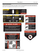
Safety Decals 36BS, 36BDS Safety Decal Identification The labels shown below are located on your mower to warn you of potential hazards and provide you with important safety information. If these decals become difficult to read or are missing from the mower, please contact GXi Parts & Service, LLC at 1-919-550-3259 or www.mower911.com for a replacement.
Control Panel and Brush Mower Components 36BS, 36BDS Throughout this manual, instructions are given on the operation of your STANLEY mower. We recommend that while going through this manual, you have your mower available for quick and easy access in order to orient yourself with the controls, maintenance and orientation of different parts. Please read through the manual before operating. Control Panel Below, you will find a diagram of the control panel.
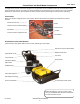
Assembly Instructions Step 1: Front Assist Wheel Assembly The mower is shipped in a steel shipping rack (see adjacent photo). Note: Some mowers are shipped with the front wheels pre-assembled. A. Remove the rack by removing the front mounting bolt. B. Remove packaging materials surrounding the front skid wheel and remove the bolt. Retain the bolt, spacer, nut and bushing for future use. C. Remove the fastener holding the bolt to the steel shipping rack.
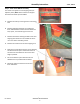
Assembly Instructions 36BS, 36BDS Step 2: Mower Assembly Instructions A. Attach handle bars using the upper hole position setting. Using this hole position sets the handle bars several inches lower. Use the lower hole position raising the handle bar location by several inches for comfort, if necessary. These hole positions can also be used for adjusting the handle bar location for operators of different heights and arm lengths. Select the height that is most comfortable for you. B.
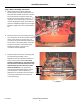
Assembly Instructions 36BS, 36BDS Step 3: Wire Harness Assembly and Connections The pre-wired handle bar assembly has a total of four (4) connections. Route the wire harness as shown in the top right photo and make the following connections indentified by number in the other photos: 1. Route the smaller, white, 2-pin connector through a hole in the chassis and connect it to the blade activation safety switch 2-pin connector. 2.
Assembly Instructions 36BS, 36BDS Step 5: Fuel Tank Connections Locate the fuel tank on the fuel tank bracket with the recessed area pointing toward the rear so any spills drain away from the engine. Align the fuel valve in the center of the clearance hole. Place the fuel tank straps into position, wrapping them around the tank and the bracket. Battery pan Once the fuel tank and straps are in place, securely tighten the straps using the bolts provided.
Operating Instructions 36BS, 36BDS Starting the Engine Operating the Mower 1. Make sure the brake has been moved to the OFF Position. 2. Push down and hold the operator presence control levers on the handle bar with both hands. 3. The forward and reverse levers are spring loaded to the neutral position. 4. To drive the mower forward, slide both hands slightly back on the handle bar and gently squeeze the forward levers toward the handle bar.
Operating Instructions 36BS, 36BDS Disengaging Hydrostatic Drive Units Return to Neutral Before physically moving the mower when the engine is NOT running, the hydrostatic drive units need to be disengaged into free-wheel mode. If the mower creeps or will not stop as desired when the handles are in neutral position, adjustments are necessary. CAUTION: Be sure the engine is OFF before you open the hydro access panel. 1. Remove the bolts to access hydro panel.
Operating Instructions 36BS, 36BDS Cutting Brush WARNING Thoroughly inspect the area where you plan to use the mower. Look for items such as stones, sticks , wire, and other foreign objects. If struck by the mower, these and other objects may become projectiles that could lead to serious injury or death. Clear area of all debris. Keep people and pets at a safe distance. DANGER DANGER! Do not operate the mower with defective guards, shields, or without the safety devices securely in place. 1.
Operating Instructions 9. Tighten the blade pivot nuts properly. 10. Refasten the access hole cover to the deck to prevent debris from entering underneath the guard. 11. Inspect the work done to the blade system to make certain everything is properly secured. Note: Check to be sure blades rotate freely. 12. Replace the mower guard and the visual warning disk and secure both properly. 13. Start the engine and blades safely and properly.
General Maintenance 36BS, 36BDS Fuel The Importance of Maintenance Regular maintenance is essential to ensure your brush mower continues to deliver safe and high-quality performance. DANGER DANGER: Gasoline is highly flammable and explosive. Do not add fuel while the engine is running or is hot. Keep open flames, sparks, and heat away from the fuel and store fuel in containers specifically designed for that purpose. Add fuel outdoors only and if the fuel is spilled, do not start the engine.
36BS, 36BDS Maintenance Schedule Time Interval Item Procedure Break-in Every 8 hrs Every 40 hrs Every 100 (first 5 hrs) (daily) (weekly) hrs (Bi-weekly) Belts Inspect (adjust if needed) Blades Inspect and Sharpen X Engine Air Filter Inspect (see Engine Owner’s Manual) X Engine Cooling Areas Clean (see Engine Owner’s Manual) X X X Check (see Engine Owner’s Manual) Engine Oil X Change (see Engine Owner’s Manual) X Engine Oil Filter Change (see Engine Owner’s Manual) X Engine Spark Pl
Service Adjustments 36BS, 36BDS DANGER IMPORTANT! The brush mower blades do NOT stop quickly. Visual indication that the blades are turning is provided at the center of the belt guard. DO NOT approach the brush mower deck for service, cleaning, removing debris, or for any other reason until after the visual warning disk has stopped completely. Even at slow speeds the blades can cause serious injury or death.
Service Adjustments 36BS, 36BDS Hydro System Maintenance Safety System Adjustments The hydrostatic drives are coupled to the output drives with a multi-v belt. Occasional retensioning of the belt may be necessary. If performance decreases or hydro control handles are activated and the wheels do not turn, inspect the multi-v belt. 1. Remove the hydro access panel. WARNING WARNING: Do not bypass, modify, alter, or disconnect the safety system.
Lubrication Points 36BS, 36BDS To ensure proper lubrication of moving parts, GXi recommends that you lubricate the following components with a high-quality, EP2 high-temperature-based grease or equivalent. Should the conditions of operation be more severe than normal, the lubrication interval may need to be shortened. GTR/OPE grease is the recommended lubricant. 2. Blade activation rod supports (2 locations: one at the support under the fuel tank bracket and one adjacent to the engine.
Troubleshooting Problem Possible Causes Solution Engine will not start 1. 2. 3. 4. 5. 6. Key in the OFF position Insufficient fuel in the tank Air bubble in the fuel line Fuel valve in OFF position Choke not ON Choke linkage out of adjustment Low engine oil Blade control in ON position Loose spark plug wire Fouled spark plug Plugged or dirty air filter Bad gasoline Plugged or dirty fuel filter Safety switches out of alignment or loose Dead battery (electric start models) 1. 2. 3. 4. 5. 6. 7. 8. 9. 10.
Troubleshooting 36BS, 36BDS Problem Possible Causes Solution Mower will not move forward or reverse 1. Brake ON 2. Bypass levers pulled out 1. Release brake on control panel 2. Ensure bypass pins are retracted Cannot move mower when the engine is off 1. Bypass not engaged 1. Pull left and right bypass pins and set them in slots in the chassis (p. 11) Engine is overheating 1. 2. 3. 4. 5. 6. 7. 1. 2. 3. 4. 5. 6. 7.
Limited Warranty & Service Products Covered by this Warranty 36BS, 36BDS Length of Warranty: *(from the date of original retail purchase) Residential Commercial Rental Engine Manufacturer’s warranty Manufacturer’s warranty Transmission Manufacturer’s warranty Manufacturer’s warranty Mower frame Lifetime (original owner only) Belts, Tires, Battery Lifetime (original owner only) 90 days Manufacturer’s warranty Manufacturer’s warranty 90 days 90 days 90 days Attachments 1 yr limited 1 yr li