
Stanley-Aoife-Eco Stove manual

FLUES
Flues should be vertical wherever possible and
where a bend is necessary, it should not make an
angle of more than 45
o
with the vertical. Horizontal
flue runs should be avoided except in the case of a
back outlet connection where the length of the hori-
zontal section should not exceed 150mm.
CHIMNEY
The Aoife is a radiant room heater and must be con-
nected to a chimney of the proper size and type. The
chimney must have a diameter of at least 150mm.
Never connect to a smaller size chimney. Do not
connect to a chimney serving another appliance.
Minimum chimney height 4.5 meters from floor on
which stove is installed. The stove is supplied with a
5” flue spigot, the flue installation will require a 5” to
6” increaser which must be fitted within 1 meter of
flue outlet.
A flue that has proved to be unsatisfactory, particu-
larly with regard to down draught should not be used
for venting this appliance until it has been examined
and any faults corrected. An existing masonry chim-
ney should be inspected and if necessary repaired
by a competent mason or relined using an approved
lining system.
The stove must be connected to a chimney with a
minimum continuous draught of 0.06 w.g. Poor
draught conditions will result in poor performance.
All register plates, restricter plates, damper etc.,
which could obstruct the flue at a future date should
be removed before connecting this appliance.
If connecting to an existing chimney with a flue
diameter of more that 8” it is recommend to line the
flue using a suitable stainless steel flue liner.
Where a masonry chimney is not available a propri-
etary type of 6”/150mm - twin wall, fully insulated
pipe may be used. The pipe must terminate at a
point not lower than the main ridge of adjacent out-
side obstructions. With such installation, access to
the chimney must be provided for cleaning purpos-
es.
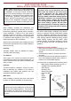
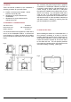
A chimney / flue termination must be located to min-
imise wind effects, a basic guide is that the distance
from the termination to the roof should be at be at
least 2300mm when measured horizontally and at
least 1000mm when measured vertically, (see
Fig.2). In circumstances where there are adjoining
buildings/ structures / roof openings there are addi-
tional requirements, please refer to building regula-
tions part J.
Fig. 2
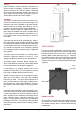
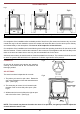
TOP FLUE EXIT
For the top outlet configuration, remove the blank-
ing plate from the hob, remove the flue spigot from
the back plate and fix it to the hob. Fix the outlet
blanking plate to back plate (see Fig. 3). Push the
flue outlet connector pipe (not supplied) into the flue
spigot and cement into place using approved fire
cement ensuring that no cement blocks the flue pas-
sageway.
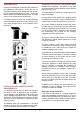
Fig.3
Top Outlet
Rear Outlet
REAR FLUE EXIT
Push the flue connector pipe (not supplied) into the
flue spigot and cement into place using approved
fire cement ensuring that no cement blocks the flue
passageway.
7