
Operation Manual


9
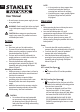
Accuracy Check and
Calibration
NOTE:
• The laser tools are sealed and calibrated at the
•
future use.
• The laser tool should be checked regularly to ensure
its accuracies, especially for precise layouts.
• When performing the accuracy checks, use the
the easier to measure the accuracy of the laser.
• The lock must be in the unlocked position to allow
the laser tool to self-level before checking the
accuracy.
SCAN DIRECTION (FIG. E)
Checking the horizontal scan calibration of the laser
requires two walls 30' (9m) apart. It is important to
than the distance of the applications for which the tool
will be used.
facing straight ahead toward the opposing wall
2.
vertical beam, mark the beam position on the
opposing wall directly across from the laser. Always
3.
Pivot the laser -90 degree to the left of center and
mark the beam position (a) on the opposing wall.
4.
Pivot the laser +90 degrees to the right of center
and mark the beam position (b) on the opposing
wall.
Measure the vertical distance between the
lowest mark (a) and the highest mark (b). If the
measurement is greater than the values shown
below, the laser must be serviced at an authorized
service center.
Distance
Between Walls
Allowable Distance
Between Marks
30' (9.0m)
PITCH DIRECTION (FIG. F)
Checking the horizontal pitch calibration of the
applications for which the tool will be used.
bracket or mount on tripod close to the wall
with the laser facing straight ahead toward the
opposing wall (0 degree position).
2.
laser toward the opposite wall and approximately
parallel to the adjacent wall.
3.
Mark the center of the beam at two locations (c, d)
at least 30' (9m) apart.
4.
Reposition the laser to the opposite wall with the
laser facing straight ahead toward the first wall
laser back toward the first wall and approximately
parallel to the adjacent wall.
Adjust the height of the laser so that the center of
the beam is aligned with the nearest mark (d).
7.
Mark the center of the beam (e) directly above or
below the farthest mark (c).
Measure the distance between these two marks
shown below, the laser must be serviced at an
authorized service center.
Distance
Between Walls
Allowable Distance
Between Marks
30' (9.0m)