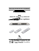
INSTALLATION AND INSTRUCTION MANUAL Models 2364LED, 2464LED and 2564LED ® Plus Lightbars PLIT429 REV.
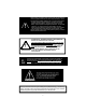
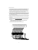
When mounting your lightbar, please be sure to keep any radio frequency sensitive equipment at least 20” from the bar and power cable(s). This is especially critical in lightbars utilizing strobes. Our strobe power supplies have been designed to limit RFI emissions, but certain very sensitive equipment may still be affected. Symptoms may include, but are not limited to, sporadic operation and degraded performance. Star Headlight & Lantern Co., Inc.
Please Note: These instructions are provided as a general guideline only. Specific mounting, wiring, and/or weather-sealing may be necessary and are the sole responsibility of the installer. Star Headlight & Lantern Co., Inc. assumes no responsibility for the integrity of the installation for this or any of its products.
QUICK-INSTALL WIRING GUIDE ! WIRE COLORS AND FUNCTIONS WILL VARY FROM HARNESS TO HARNESS. PLEASE BE SURE TO CORRECTLY IDENTIFY YOUR HARNESS AND USE THE CORRESPONDING TABLE. IN ADDITION, ALL LIGHTBARS ARE SHIPPED WITH A WORKSHEET THAT IDENTIFIES THE FUNCTION FOR EACH WIRE COLOR IN THAT SPECIFIC LIGHTBAR.
QUICK-INSTALL WIRING GUIDE ! WIRE COLORS AND FUNCTIONS WILL VARY FROM HARNESS TO HARNESS. PLEASE BE SURE TO CORRECTLY IDENTIFY YOUR HARNESS AND USE THE CORRESPONDING TABLE. IN ADDITION, ALL LIGHTBARS ARE SHIPPED WITH A WORKSHEET THAT IDENTIFIES THE FUNCTION FOR EACH WIRE COLOR IN THAT SPECIFIC LIGHTBAR.
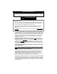
Mounting Instructions Please review the separate Mounting Bracket manual that is also enclosed with your bar for mounting instructions. Wiring Harness Replacement All standard lightbar models are designed for 12VDC negative ground vehicles only. Reverse polarity will cause serious damage to the lightbar and/or vehicle. Contact the automotive dealer if there are any doubts about the polarity of your vehicle.
(Direct Wiring Guide CONT’D) 4. The wiring harness will connect to one or more terminal blocks inside the lightbar. All of the wires coming from the harness are terminated on one side of the terminal block and the wires leading to the internal components terminate on the opposite side of the terminal block. The Wiring Guide on pages 1-2 lists the wire colors from the harness in the same order as they are connected to the terminal block(s).
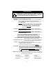
Electrical Connections All standard lightbar models are designed for 12VDC negative ground vehicles only. Reverse polarity will cause serious damage to the lightbar and/or vehicle. Contact the automotive dealer if there are any doubts about the polarity of your vehicle. RF INTERFERENCE Please take the following steps to help eliminate any Radio Frequency Interference (RFI) with your two-way radio. • DO NOT run the power wire for the lightbar along same path as any antenna wires.
Wire Functions WIRE COLORS AND FUNCTIONS WILL VARY FROM HARNESS TO HARNESS. PLEASE BE SURE TO CORRECTLY IDENTIFY YOUR HARNESS AND USE THE CORRESPONDING TABLE IN THE WIRING GUIDE ON PAGES 1-2. IN ADDITION, ALL LIGHTBARS ARE SHIPPED WITH A WORKSHEET THAT IDENTIFIES THE FUNCTION FOR EACH WIRE COLOR IN THAT SPECIFIC LIGHTBAR. ! Ground - Connect to the negative side of the battery. Bare/Shield - Connect to the negative side of the battery. Power (Red) - Connect to +12-24 VDC through your switch.
Pattern Programming Before changing the pattern, please review these key points about programming the lightbar: • The lightbar consists of two separate circuits. One circuit controls the driver's side and the other circuit controls the passenger's side. • The driver's side circuit and passenger's side circuit are programmed with different wires. The colors will vary depending upon your harness.
Flash Patterns Flash Pattern # Pattern Description CPS** 1 Alternating Flicker 1.0 2 Alternating Fast Double Flash 3.3 3 Alternating Triple Flash 2.5 4 Alternating PSU Flicker 0.7 5 Alternating PSU Random 0.6 6 Alternating Quad Flash 1.0 7 Alternating Quad Flash w/Post-Pop 1.0 8 Alternating Single Flash 1.0 9 Alternating Slow Double Flash 1.
Synchronization You can synchronize up to six total If you will be synchronizing your light with any of our following: approved lights. products, please note the • All units that are to be synchronized MUST have the same Pattern. • To check pattern compatibility with other products, review the Pattern List for each product, noting the Pattern. Certain patterns are compatible with some lights, but not compatible with others.
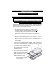
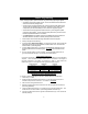
Parts Please note that these items are not drawn to scale. Many have been enlarged to show more detail.
(Parts CONT’D) *=COLOR Please note that these items are not drawn to scale.
Optional Switch Boxes SP3860-1 SP3860-4 SP3860-2 ROTATORS STROBES LEFT ALLEY SP3860-3 SP1515 SB1515 SP3015 SB3015 RIGHT ALLEY WORK LIGHTS MODE 1 2 3 FLASHERS SB4020 ROTATORS STROBES LEFT ALLEY RIGHT ALLEY WORK LIGHTS GRILL LIGHTS HEADLIGHT FLASHER CORNER LIGHTS SB4040 FLASHERS SB4020T SB4425 -12- TAKE DOWN
Warranty ONE YEAR LIMITED WARRANTY LED FIVE YEAR LIMITED WARRANTY The manufacturer warrants each new product, under normal use, against factory defects in material and workmanship for one year after the date of purchase. The manufacturer warrants the LED components in this light against factory defects in material and workmanship for five years after the date of purchase. The owner will be responsible for returning to the Service Center any defective item(s) with the transportation costs prepaid.