
Owner's manual


-5-
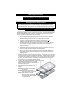
• For all standard Razor lightbars, 15 feet of cable (plus a drain wire and a foil shield) is
supplied with the bar. All wires are color coded and sized at the correct gauge. If this
length is not sufficient, it is recommended that the wire harness be completely replaced
with the only connections to be made directly at the terminal block inside the lightbar.
This will reduce the number of wire connections and help prevent any weathering
problems on these connections. Refer to the Direct Wiring Guide on pages 3-4 for
further instructions on this.
• CAUTION: All wires and switches should be rated for at least 125% of their
maximum current load. In addition, all wires connected to the positive terminal of the
battery should be fused at the battery for 125% of their rated load. The load can be
calculated by adding all lamp wattages and dividing by 13. (Load <Amps> = Total
Watts / 13 volts) Do not use 1/4" diameter glass fuses, as they are not suitable for
continuous duty above 20 amps. If you are unsure of the current draw, please contact
our Customer Service Department.
• TESTING THE LIGHTBAR BEFORE IT IS PROPERLY FUSED & INSTALLED WILL
VOID THE WARRANTY!!
• The black ground wire should be connected to the negative terminal of your vehicle’s
battery. This wire should be as short as possible in order to minimize the voltage loss
in this wire and reduce any chance of overheating.
• Your harness will contain all of the colored wires in its corresponding harness. Most
applications though, will not use every wire. The “dead” wires in the harness will be
connected to the terminal block inside your lightbar, but there will be no wires
connected to the terminal across from them. These “dead” wires can be used for
additional components that may be added at some point in the future, or they may be
used to separately switch components that are currently wired together.
• Since many of the lightbars we build have custom components, and numerous different
harnesses are used, wire colors WILL vary. You can use the Wire Guide on pages 1-2
or the worksheet shipped with each bar to identify the function of each wire If you are
still unsure of the function of a particular wire, you may test the function by grounding
the black wire and applying +12VDC to the wire in question. Be sure to use a 20-amp
fuse when testing.
All standard lightbar models are designed for 12VDC negative ground vehicles
only. Reverse polarity will cause serious damage to the lightbar and/or vehicle.
Contact the automotive dealer if there are any doubts about the polarity of your vehicle.
Please take the following steps to help eliminate any Radio Frequency Interference (RFI)
with your two-way radio.
• DO NOT run the power wire for the lightbar along same path as any antenna wires.
• DO NOT run the power wire for the lightbar along same path as any radio power wires.
• DO NOT tap power for the lightbar off of the radio power wires.
• DO NOT mount the lightbar within 20” of any antennae. Sometimes mounting the
lightbar or antenna over by just one foot can make a large difference in the
interference.
• Ensure the black wire from the lightbar has a good connection to the negative side of
the battery.
RF INTERFERENCE
Electrical Connections