INSTALLATION AND INSTRUCTION MANUAL PLITSTR341 REV F 8/4/11
When mounting your lightbar, please be sure to keep any radio frequency sensitive equipment at least 20” from the bar and power cable(s). This is especially critical in lightbars utilizing strobes. Our strobe power supplies have been designed to limit RFI emissions, but certain very sensitive equipment may still be affected. Symptoms may include, but are not limited to, sporadic operation and degraded performance. Star Headlight & Lantern Co., Inc.
Please Note: These instructions are provided as a general guideline only. Specific mounting, wiring, and/or weather-sealing may be necessary and are the sole responsibility of the installer. Star Headlight & Lantern Co., Inc. assumes no responsibility for the integrity of the installation for this or any of its products.
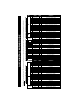
Wire Harness for Bars Without Stop/Tail/Turn Lights P271-RAZOR Wire Harness for Bars with Incandescent STT Lights P271-TOWBAR Layout 1 Wire Harness for Bars With LED STT Lights P271-TOWBAR Layout 2 Please Note: If your lightbar has an LED or incandescent traffic director in it, there will also be a separate bundled 9-conductor cable specifically for that function.
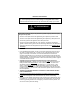
Typical 46" Lightbar Layouts Orange Brown Brown w/Yellow w/Yellow w/Yellow te hi d W /Re w Orange w/Red Brown Brown Orange w/Yellow w/Yellow w/Yellow w Wh /Y it el e lo w Main LEDs/Strobe Power White w/Brown: High Power/Low Power (Pursuit Mode) Pattern Select Ground Drain/Shield (connect to Ground) Brown w/Red Green w/Red Brown w/Red Gray Green w/Red Brown w/Red Brown w/Red Orange w/Red W w/ hit R e ed Red: Purple: Red w/Green Stripe: Black: Bare Wire: Blue Green Green w/Yellow w/Yellow {
Mounting Instructions Please review the separate Mounting Bracket manual that is also enclosed with your bar for mounting instructions. Wiring Instructions All standard lightbar models are designed for 12VDC negative ground vehicles only. Reverse polarity will cause serious damage to the lightbar and/or vehicle. Contact the automotive dealer if there are any doubts about the polarity of your vehicle.
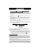
(Direct Wiring Guide CONT’D) 5. All of the wires coming from outside of the lightbar are terminated on the same side of the terminal block and the wires leading to the internal components terminate on the opposite side of the terminal block. Loosen the screws on the terminal block and remove only those wires that exit the lightbar through the hole in the base.
Electrical Connections All standard lightbar models are designed for 12VDC negative ground vehicles only. Reverse polarity will cause serious damage to the lightbar and/or vehicle. Contact the automotive dealer if there are any doubts about the polarity of your vehicle. RF INTERFERENCE Please take the following steps to help eliminate any Radio Frequency Interference (RFI) with your two-way radio. • DO NOT run the power wire for the lightbar along same path as any antenna wires.
Wire Functions PLEASE NOTE: There are three different harnesses that could be installed on your lightbar. Please review the Quick-Install Wiring Guide on page 1 for proper connection of your wires. Your harness will contain all of the colored wires, the drain wire, and the foil shield, but most applications will not use every wire. The “dead” wires in the harness will be connected to the terminal block inside your lightbar, but there will be no wires connected to the terminal across from them.
Pattern Programming ● Lightbars with LEDs or strobes can be programmed with the user’s choice of flash pattern. ● If you have both strobes and LEDs in your lightbar, programming of the strobe pack(s) and LED flasher(s) must be done separately.
LED Flash Patterns Front and Rear DLX6 and Batwing LED Patterns (LDF375-1 Flasher) Pattern 1 2 3 4 5 6 7 8 9 10 11 12 13 14 15 16 17 18 19 20 21 22 23 24 25 26 27 28 29 30 31 32 Please Note: Warning Pattern Style Pursuit Mode (1 flash/3 sec default) Alternating Slow Single (1-5 vs 6-10) (Title 13 Approved) Alternate Pursuit Mode Alternating Quad Flash (1-5 vs 6-10) Alternating Triple (1,2,6,7,8 vs 3,4,5,9,10) Alternating Quint (1,2,6,7,8 vs 3,4,5,9,10) Simultaneous Slow Single (All Modules) (Title 13 App
(LED Pattern Programming CONT’D) Takedown or Alley Light DLX6 and Batwing LED Patterns (LDF375-2 Flasher) Pattern 1 2 3 4 5 6 7 8 9 10 11 12 13 14 15 16 17 18 19 20 21 22 23 24 25 26 27 28 29 30 Warning Pattern Style Pursuit Mode (1 flash/3 sec default) Alternating Slow Single (1,3 vs 2,4) (Title 13 Approved) Alternate Pursuit Mode Alternating Quad Flash (1,3 vs 2,4) Alternating Triple (1,3 vs 2,4) Alternating Quint (1,3 vs 2,4) Simultaneous Slow Single (All Modules) (Title 13 Approved) Simultaneous Fast
(LED Pattern Programming CONT’D) Patterns for All LEDs Excluding DLX6 and Batwing (LDF398 Flasher) Pattern 1 2 3 4 5 6 7 8 9 10 11 12 13 14 15 16 17 18 19 20 21 22 23 24 25 26 27 28 29 30 Warning Pattern Style Pursuit Mode (Default) Alternating Slow Single (1-5 vs 6-10) (Title 13 Approved) Alternate Pursuit Mode Alternating Quad Flash (1-5 vs 6-10) Alternating Triple (1,2,6,7,8 vs 3,4,5,9,10) Alternating Quint (1,2,6,7,8 vs 3,4,5,9,10) Simultaneous Slow Single (All Modules) (Title 13 Approved) Simultaneo
Parts Please note that these items are not drawn to scale. Many have been enlarged to show more detail.
(Parts CONT’D) *=COLOR Please note that these items are not drawn to scale.
Switches and Switchboxes SP3860-1 ROTATORS STROBES LEFT ALLEY SP3860-2 SP3860-3 SP3860-4 SP1515 SB1515 SP3015 SB3015 RIGHT ALLEY WORK LIGHTS MODE 1 2 3 FLASHERS GRILL LIGHTS HEADLIGHT FLASHER CORNER LIGHTS SB4040 SB4020 -13- TAKE DOWN
Troubleshooting If a light on your bar fails to work, please refer to this section to help solve your problem. If you still cannot resolve your problem, please contact our Customer Service Department at 585-226-9787. The chart below contains some basic guidelines for troubleshooting any problems you may experience with your bar. The section following the chart will explain in further detail how to perform some of the troubleshooting tasks.
Determining if the bar is properly grounded: 1. While the bar is turned on, using a test meter, measure the voltage from the base of the bar itself to the negative post of the battery or a good chassis ground if the battery can’t be easily reached. You may need to scrape away a bit of anodizing or paint in order to ensure a good connection with the probe of your test meter. 2. If the difference shown is greater than .25 volts, then your ground is not sufficient. 3.
Checking multiple non-working strobe or LED heads: If two or more of the heads connected to one of the packs are not flashing, follow these steps to determine the problem: 1. Check the power to the terminal block as explained on the previous page. 2. Check that the bar is grounded properly as explained on the previous page. 3. Check all fuses, including those at the battery, at the switch panel, in the dash, and on the pack (if applicable). Remove these fuses, and check them to confirm they have not blown.
ONE YEAR LIMITED WARRANTY LED FIVE YEAR LIMITED WARRANTY The manufacturer warrants each new product, under normal use, against factory defects in material and workmanship for one year after the date of purchase. The manufacturer warrants the LED components in this light against factory defects in material and workmanship for five years after the date of purchase. The owner will be responsible for returning to the Service Center any defective item(s) with the transportation costs prepaid.