DOT MATRIX PRINTER SP317/347F USERS MANUAL GUIDE D’UTILISATION BEDIENUNGSANLEITUNG MANUALE DI ISTRUZIONI
Federal Communications Commission Radio Frequency Interference Statement This equipment has been tested and found to comply with the limits for a Class A digital device, pursuant to Part 15 of the FCC Rules. These limits are designed to provide reasonable protection against harmful interference when the equipment is operated in a commercial environment.
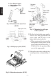
TABLE OF CONTENTS 1. LOADING THE RIBBON CARTRIDGE .......................................... 2 1-1. SP317 ........................................................................................... 2 1-2. SP347 ........................................................................................... 3 2. LOADING THE PAPER ..................................................................... 5 2-1. SP317 ........................................................................................... 5 2-2.
1. LOADING THE RIBBON CARTRIDGE ENGLISH 1-1. SP317 1 Turn the power switch on the printer to the off position. 2 To remove the front cover lift it up approx. 3cm. and pull it forward. NOTE: Do not touch the print head immediately after printing as it can be extremely hot. 3 To remove slack in the ribbon turn the ribbon feed knob of the ribbon cartridge in the direction of the arrow. 4 Align the ribbon cartridge guide with the notched part of the frame.
1 Turn the power switch on the printer to the off position. 2 To remove the front cover lift it up approx. 3cm. and pull it forward. NOTE: Do not touch the print head immediately after printing as it can be extremely hot. Front cover Power off Fig. 1-3 Removing the front cover (SP347) 3 Lift up the auto cutter and put it in a vertical position, as shown in Fig. 14. 4 Remove the packing material. Auto cutter Packing material Fig.
ENGLISH Ribbon cartridge Frame Ribbon feed knob 4 To remove slack in the ribbon turn the ribbon feed knob of the ribbon cartridge in the direction of the arrow. 5 Align the ribbon cartridge guide with the notched part of the frame. Insert the ribbon cartridge from that position until you hear a locking sound. Insert the ink ribbon between the print head and the ribbon separator. Make sure that the ink ribbon is not protruding beyond the ribbon separator.
2-1. SP317 1 Turn the power switch on the printer to the off position. 2 Set DIP switch 2-4 to match the width of the paper that is being used. (Refer to Installation Manual for DIP switch settings.) DIP switches ON OFF 2-4 3.25 inches 3.0 inches 2.25 inches (All the switches in the DIP switch array are factory preset to the “ON” position.) 3 To remove the rear cover lift it up approx. 3cm and push it backwards. Fig. 2-1 Removing the rear cover (SP317) 4 Dependant on the width of the paper (2.
ENGLISH 5 Set the left and right paper guides. Leave a 0.5 mm gap between the paper guide and the edge of the paper and fix the lock lever. • When you insert the stop ring that corresponds to the groove of the paper guide shaft shown in Fig. 23, that will be the position when you set the paper guide. Fig. 2-3 Setting of the paper guide (SP317) Fig. 2-4 Loading the paper (SP317) 6 Turn the power switch on the printer to the on position. 7 Cut off the front edge of the roll paper in a straight line.
1 Turn the power switch on the printer to the off position. 2 To remove the front cover lift it up approx. 3cm. and pull it forward. NOTE: Do not touch the print head immediately after printing as it can be extremely hot. 3 To remove the rear cover lift it up approx. 3cm and push it backwards. Rear cover Power off Fig. 2-5 Removing the rear cover (SP347) 4 Adjust DIP switch 2-4, the roll paper holder and the adjust lever position according to the width and thickness of the roll paper that is being used.
A: One Sheet of paper (standard position) B: Copy paper Roll paper holders ENGLISH Lock lever Paper guides Adjust lever Paper holder mount notch for 3-inch paper For 2.25-inch paper Paper holder mount notch for 3-inch paper Fig. 2-6 Position of the adjust lever (SP347) Paper guide shaft Paper guide 2.25 inch 3 inch 3.35 inch For 2.25-inch paper Fig. 2-7 Mounting the roll paper holders (SP347) Paper guide Fig. 2-8 Roll paper guide (SP347) 5 Set the left and right paper guides. Leave a 0.
–9– ENGLISH 7 Turn the power switch on the printer to the on position. 8 Cut the tip of the roll paper in a straight line. • In case the front edge of the paper is fastened with a label, etc., remove the adhesive part of the label. If any adhesive remains on the paper, it will stick onto the roller of the printer, causing the paper to misfeed. 9 Observe the winding direction of the roll paper and insert the paper until it stops under the guide.
Auto cutter ENGLISH Lower paper Paper insertion slit Paper insetion slit Upper paper Lower paper Upper paper Print head Platen Platen Print head Fig. 2-12 Insertion of the paper into the auto cutter (When using copying paper) (SP347) C Pull on the edge of the paper to remove any slack and then lower the auto cutter. Paper D Insert the paper through the front outlet cover paper outlet and then replace the front cover by reversing the reAuto cutter moval steps.
Fig. 3-1 Control panel 1 “ON LINE” switch Switches the printer between “ON LINE” and “OFF LINE”. Whenever the printer switches between “ON LINE” and “OFF LINE”, the buzzer gives one short beep (“ON LINE” and “OFF LINE” switching is possible only when the paper is loaded in the printer.) 2 “FEED” switch • When this switch is pressed and then released within 0.5 sec., the paper feeds one line. • When this switch is depressed for more than 0.5 sec., the paper feeds continuously.
TABLE DES MATIÈRES 1. INSTALLATION D’UNE CARTOUCHE DE RUBAN .................. 14 1-1. SP317 ......................................................................................... 14 1-2. SP347 ......................................................................................... 15 2. CHARGEMENT DU PAPIER .......................................................... 17 2-1. SP317 ......................................................................................... 17 2-2. SP347 .....................
1. INSTALLATION D’UNE CARTOUCHE DE RUBAN 1-1. SP317 FRANÇAIS 1 Mettez le commutateur d’alimentation de l’imprimante sur la position d’arrêt. 2 Pour retirer le cache avant, soulevez-le d’environ 3 cm, puis tirez-le vers l’avant. N.B. : Ne touchez pas la tête d’impression immédiatement après une impression ; en effet, celle-ci peut être très chaude. 3 Pour tendre le ruban, tournez le bouton d’alimentation du ruban de la cartouche dans la direction de la flèche.
Cache avant 1 Mettez le commutateur d’alimentation de l’imprimante sur la position d’arrêt. 2 Pour retirer le cache avant, soulevez-le d’environ 3 cm, puis tirez-le vers l’avant. N.B. : Ne touchez pas la tête d’impression immédiatement après une impression ; en effet, celle-ci peut être très chaude. Hors tension Fig.
Cartouche de ruban FRANÇAIS Bouton d’alimentation du ruban Cadre 4 Pour tendre le ruban, tournez le bouton d’alimentation du ruban de la cartouche dans la direction de la flèche. 5 Alignez le guide de la cartouche de ruban sur l’encoche du cadre, puis appuyez légèrement sur la cartouche de ruban afin qu’elle se mette en place. Vous entendrez un déclic une fois la cartouche bien en place. Insérez ensuite le ruban encreur entre la tête d’impression et la protection du ruban.
2. CHARGEMENT DU PAPIER 1 Mettez le commutateur d’alimentation de l’imprimante sur la position d’arrêt. 2 Réglez l’interrupteur DIP 2-4 en fonction de la largeur du papier utilisé. (Se référer au Manuel d’installation pour les réglages des microrupteurs). Interrupteurs DIP 2-4 ON OFF 3,25 pouces 2,25 pouces 3,0 pouces (Chacun des interrupteurs DIP sont préréglés sur la position “OUI”.) 3 Pour retirer le cache arrière, releFig.
FRANÇAIS 5 Réglez la position des guides de papier gauche et droit. Veillez à laisser un espace de 0,5 mm entre l’extrémité du guide et du papier, puis bloquez le levier de verrouillage. • Pour régler la position des guides de papier, placez les anneaux d’arrêt dans les espaces sur l’axe des guides de papier qui correspondent à la largeur du papier à charger (voyez la figure 2-3). Fig.
1 Mettez le commutateur d’alimentation de l’imprimante sur la position d’arrêt. 2 Pour retirer le cache avant, soulevez-le d’environ 3 cm, puis tirez-le vers l’avant. N.B. : Ne touchez pas la tête d’impression immédiatement après une impression ; en effet, celle-ci peut être très chaude. 3 Pour retirer le cache arrière, relevez-le d’environ 3 cm, puis repoussez-le vers l’arrière. Cache arrière Hors tension Fig.
A: Une feuille de papier (position standard) B: Papier de copie Attaches pour rouleau de papier Levier de verrouillage Guides du papier Levier d’ajustement Encoche de fixation pour support de papier de 3 pouces FRANÇAIS Pour papier de 2,25 pouces Encoche de fixation pour support de papier de 3 pouces Fig. 2-6 Positionnement du levier d’ajustement (SP347) Axe de guides de papier Guide de papier 2,25 pouces 3 pouces 3,25 pouces Guide de papier Fig.
– 21 – FRANÇAIS 7 Mettez le commutateur d’alimentation de l’imprimante sur la position de marche. 8 Coupez l’extrémité du papier en veillant à couper droit. • Si l’extrémité du papier est fixée à l’aide d’un adhésif, il convient de l’éliminer. En effet, toute trace de matière adhésive sur le papier que vous insérez dans l’imprimante risque d’adhérer au rouleau et d’empêcher l’alimentation correcte du papier.
Coupoir automatique Deuxième feuille Fente d’insertion du papier Fente d’insertion du papier Première feuille Deuxième feuille FRANÇAIS Première feuille Tête d’impression Cylindre d’impression Cylindre d’impression Tête d’impression Fig. 2-12 Insertion du papier dans le coupoir automatique (avec papier de copie) (SP347) C Tirez sur l’extrémité du papier afin de tendre le papier, puis rabaisser le coupoir automatique.
1 Touche “en ligne” ON LINE Cette touche permet de commuter entre les états “en ligne” et “hors POWER ligne”. Un bip sonore court retentit 3 à chaque fois que l’imprimante passe ALARM 4 d’un état à l’autre. Vous ne pouvez modifier l’état que si du papier est 5 chargé dans l’imprimante. ON LINE 2 Touche d’avance FEED 1 • Si vous appuyez sur la touche, FEED puis la relâchez dans la demi-se2 conde, le papier avance d’une ligne. • Si vous appuyez sur la touche Fig.
INHALTSVERZEICHNIS 1. EINLEGEN DER FARBBANDKASSETTE ................................... 26 1-1. SP317 ......................................................................................... 26 1-2. SP347 ......................................................................................... 27 2. EINLEGEN DES PAPIERS .............................................................. 29 2-1. SP317 ......................................................................................... 29 2-2. SP347 ........
1. EINLEGEN DER FARBBANDKASSETTE 1-1. SP317 DEUTSCH 1 Den Netzschalter am Drucker in Aus-Stellung stellen. 2 Zum Abnehmen der Frontabdeckung diese ca. 3 cm anheben, und nach vorne ziehen. HINWEIS: Nicht den Druckkopf sofort nach dem Drukken berühren, da er sehr heiß sein kann. 3 Um Schlaufen im Farbband aufzuwickeln, den Farbbandzuführknopf der Farbbandkassette in Pfeilrichtung drehen. 4 Die Farbbandkassettenführung mit dem eingekerbten Teil am Rahmen ausrichten.
1-2. SP347 Frontabdeckung DEUTSCH 1 Den Netzschalter des Druckers in Aus-Stellung stellen. 2 Zum Abnehmen der Frontabdeckung diese ca. 3 cm anheben, und nach vorne ziehen. HINWEIS: Nicht den Druckkopf sofort nach dem Drukken berühren, da er sehr heißsein kann. Netzschalter aus Abb. 1-3 Abnehmen der Frontabdeckung (SP347) 3 Die automatische Abschneideinheit anheben und in vertikale Position stellen, wie in der Abbildung 1-4 gezeigt. 4 Das Verpackungsmaterial entfernen.
Farbbandkassette DEUTSCH Farbbandzuführknopf Rahmen 4 Um Schlaufen im Farbband aufzuwickeln, den Farbbandzuführknopf der Farbbandkassette in Pfeilrichtung drehen. 5 Die Farbbandkassette mit dem gekerbten Teil am Rahmen ausrichten. Die Farbbandkassette aus dieser Position bis zum hörbaren Einrasten eindrücken. Das Farbband zwischen dem Druckkopf und dem Farbband-Trenner einführen. Sicherstellen, daßkein Farbband über den Farbband-Trenner herausragt.
2. EINLEGEN DES PAPIERS 2-1. SP317 DIPSchalter ON OFF 2-4 3,25 Zoll 3,0 Zoll 2,25 Zoll (Alle Schalter in der DIP-Schalterleiste sind ab Werk auf “ON” gestellt.) 3 Zum Entfernen der Rückabdeckung diese ca. 3 cm anheben und nach Abb. 2-1 Entfernen der Rückabdeckung hinten drücken. (SP317) 4 Je nach der Breite des Papiers (2,25 oder 3 Zoll) die Papierrollenhalter auf die vorgeschriebene Position ausrichten. Abb.
5 Stellen Sie die linke und rechte Papierführung ein. Lassen Sie einen 0,5 mm breiten Abstand zwischen Papierführung und Papierkante und stellen Sie den Sperrhebel fest. • Indem Sie den Sicherungsring einsetzen, der der Rille der Papierführungswelle in Abb. 2-3 entspricht, legen Sie die Position für die Papierführung fest. Abb. 2-3 Einstellung der Papierführung 6 Den Netzschalter des Druckers in Ein-Stellung stellen.
1 Den Netzschalter des Druckers in Aus-Stellung stellen. 2 Zum Entfernen der Frontabdeckung diese ca. 3 cm anheben und nach vorne ziehen. HINWEIS: Nicht den Druckkopf sofort nach dem Drukken berühren, da er sehr heiß sein kann. 3 Zum Entfernen der Rückabdeckung diese ca. 3 cm anheben und nach hinten drücken. Rückabdeckung Netzschalter aus Abb.
A: Ein Blatt Papier (Normalposition) B: Kopierpapier Rollenpapierhalter Sperrhebel Papierführungen Einstellhebel PapierhalterHaltekerbe für 3-Zoll-Papier Für 2,25-ZollPapier DEUTSCH Abb. 2-6 Position des Einstellhebels (SP347) PapierhalterHaltekerbe für 3-Zoll-Papier Papierführungswelle Für 2,25-Zoll-Papier Abb. 2-7 Anbringen der Rollenpapierhalter (SP347) 5 Stellen Sie die linke und rechte Papierführung ein.
– 33 – DEUTSCH 7 Den Netzschalter des Druckers in Ein-Stellung stellen. 8 Schneiden Sie die Vorderkante des Rollenpapiers in einer geraden Linie ab. • Wenn die Vorderkante des Papiers mit einem Aufkleber etc. festgeklebt ist, ziehen Sie den Aufkleber ab. Wenn Klebstoff auf dem Papier verbleibt, kann er an der Walze anhaften und Fehleinzug bewirken. 9 Beachten Sie die Wickelrichtung des Rollenpapiers, und setzen Sie das Papier ein, bis es unter der Führung stoppt.
Automatische Abschneideinheit Unteres Papier Papiereinführschlitz Oberes Papier Papiereinführschlitz Unteres Papier Oberes PapierI Druckwalze Druckkopf Druckwalze Druckkopf DEUTSCH Abb. 2-12 Einsetzen des Papiers in den automatischen Abschneider (bei Verwendung von Durchschlagpapier) (SP347) C Ziehen Sie die Kante des Papierstau, um Schlaufen zu beseitigen, und senken Sie dann die automatische Abschneideinheit ab.
POWER 3 ALARM 4 5 ON LINE 1 FEED 2 Abb. 3-1 Bedienfeld 1 Taste ON LINE Schaltet den Drucker zwischen Online und Off-line Betrieb um. Bei jedem Umschalten zwischen Online und Off-line wird ein kurzer Piepton ausgegeben (Umschalten ist nur möglich, wenn Papier im Drukker eingelegt ist.) 2 FEED-Schalter • Wenn dieser Schalter gedrückt und dann innerhalb von 0,5 s losgelassen wird, wird das Papier um eine Zeile vorgeschoben.
INDICE 1. CARICAMENTO DELLA CARTUCCIA DEL NASTRO .............. 38 1-1. SP317 ......................................................................................... 38 1-2. SP347 ......................................................................................... 39 2. CARICAMENTO DELLA CARTA ................................................. 41 2-1. SP317 ......................................................................................... 41 2-2. SP347 ..........................................
1. CARICAMENTO DELLA CARTUCCIA DEL NASTRO 1-1. SP317 ITALIANO 1 Regolare l’interruttore di alimentazione della stampante sulla posizione di spegnimento. 2 Per rimuovere il coperchio anteriore sollevarlo di circa 3 cm e tirarlo in avanti. NOTA: Non toccare la testina di stampa subito dopo la stampa perché può essere molto calda. 3 Per eliminare allentamenti del nastro girare la manopola di avanzamento del nastro sulla cartuccia del nastro in direzione della freccia.
1-2. SP347 Coperchio anteriore 1 Regolare l’interruttore di alimentazione della stampante sulla posizione di spegnimento. 2 Per rimuovere il coperchio anteriore sollevarlo di circa 3 cm e tirarlo in avanti. NOTA: Non toccare la testina di stampa subito dopo la stampa perché può essere molto calda. Spegnere ITALIANO Fig.
Cartuccia del nastro Manopola di avanzamento del nastro Telaio ITALIANO 4 Per eliminare allentamenti del nastro girare la manopola di avanzamento del nastro sulla cartuccia del nastro in direzione della freccia. 5 Allineare la guida della cartuccia del nastro con la parte incassata del telaio. Inserire la cartuccia del nastro da quella posizione fino a quando si sente uno scatto. Inserire il nastro inchiostro tra la testina di stampa e il separatatore nastro.
2. CARICAMENTO DELLA CARTA 2-1. SP317 Interruttori DIP ON OFF 2-4 3,25 pollici 3,0 pollici 2,25 pollici (Tutti gli interruttori nel gruppo di interruttori DIP sono stati predisposti in fabbrica sulla posizione “ON”.) Fig. 2-1 Rimozione del coperchio posteriore 3 Per rimuovere il coperchio poste(SP317) riore, sollevarlo di circa 3 cm e spingerlo indietro. 4 A seconda della larghezza della carta (2,25 o 3 pollici), allineare i supporti della carta in rotolo alle posizioni specificate. Fig.
5 Regolare le guide della carta sinistra e destra. Lasciare uno spazio di 0,5 mm tra la guida della carta e il bordo della carta e fissare la leva di blocco. • Quando si inserisce l’anello di fermo corrispondente alla scanalatura sull’asta delle guide della carta mostrata nella Fig. 2-3, quella sarà la posizione quando si fissa la guida della carta. Fig. 2-3 Regolazione delle guide della carta (SP317) 6 Regolare l’interruttore di alimenta- ITALIANO zione della stampante sulla posizione di accensione.
2-2. SP347 1 Regolare l’interruttore di alimentazione della stampante sulla posizione di spegnimento. 2 Per rimuovere il coperchio anteriore sollevarlo di circa 3 cm e tirarlo in avanti. NOTA: Non toccare la testina di stampa subito dopo la stampa perché può essere molto calda. 3 Per rimuovere il coperchio posteriore sollevarlo di circa 3 cm e tirarlo indietro. ITALIANO Coperchio posteriore Spegnere Fig.
A: Un foglio di carta (posizione standard) B: Carta carbone Supporti carta in rotolo Leva di blocco Guide della carta Leva di regolazione Tacca di montaggio supporto carta per carta da 3 pollici Per carta da 2,25 pollici Tacca di montaggio supporto carta per carta da 3 pollici Fig. 2-6 Posizione della leva di regolazione (SP347) Asta della guida della carta Per carta da 2,25 pollici Fig. 2-7 Montaggio dei supporti carta in rotolo (SP347) ITALIANO 5 Regolare le guide della carta sinistra e destra.
– 45 – ITALIANO 7 Regolare l’interruttore di alimentazione della stampante sulla posizione di accensione. 8 Tagliare la parte iniziale della carta in rotolo su una linea diritta. • Se la parte iniziale della carta è fissata con un’etichetta, ecc., rimuovere la parte adesiva dell’etichetta. Se rimane dell’adesivo sulla carta, si può appiccicare al rullo della stampante, causando errori di avanzamento della carta.
Taglierina automatica Carta inferiore Fessura di inserimento carta Carta superiore Fessura di inserimento carta Carta inferiore Carta superiore Testina di stampa Rullo Rullo Testina di stampa Fig. 2-12 Inserimento della carta nella taglierina automatica (quando si usa carta carbone) (SP347) ITALIANO C Tirare il bordo della carta per rimuovere eventuali allentamenti e quindi abbassare la taglierina automatica.
POWER 3 ALARM 4 5 ON LINE 1 FEED 2 Fig. 3-1 Pannello di controllo 1 Interruttore “ON LINE” Alterna lo stato dello stampante tra “ON LINE” e “OFF LINE”. Quando la stampante alterna tra “ON LINE” e “OFF LINE”, il cicalino emette un breve segnale acustico. (la commutazione “ON LINE” e “OFF LINE” è possibile solo quando la carta è caricata nella stampante.) 2 Interruttore “FEED” • Quando questo interruttore viene premuto per pió di mezzo secondo, la carta avanza continuamente.
APPENDIX Connectors and Signals (Serial Interface) RS-232C 1 F-GND I/O direction — 2 3 TXD RXD OUT IN Transmitted data Received data 4 RTS OUT 5 CTS IN Data transmission request signal. This is always “SPACE” when the printer is turned on. This signal changes to “SPACE” when host computer is ready to transmit data. (In this instance, the printer does not check this signal.
20 mA current loop (option) Signal name I/O direction Function 9 TTY TXDR — Indicates the ground side of the data signal of 20 mA loop current. Transmitted data of 20 mA current loop. 10 TTY TXD OUT 17 TTY TXDR — 18 TTY RXDR — 19 23 TTY RXD TTY RXDR IN — Received data of 20 mA current loop. Indicates the ground side of the data signal at 20mA loop current. 24 TTY TXD OUT 25 TTY RXD IN Transmission data of 20 mA current loop. Reception data of 20 mA current loop.
Interface Connections (Serial Intefface) Example of interface connections for an IBM PC – 51 – APPENDIX The following is a basic example of interface connections. (For interface connections, refer to the specifications for the respective interface.) An IBM PC type serial port is shown in below.
Connectors and Signals (Parallel Interface) 1 Signal Name STROBE IN 2-9 DATA1-8 IN 10 ACK OUT 11 BUSY OUT 12 18 19-30 31 PAPER OUT OUT SELECTED OUT N/C SIGNAL GND CHASSIS GND +5VDC GND RESET IN 32 ERROR 33 34 35 36 EXT GND COMPULSION OUT N/C – – – Pin No. 13 14-15 16 APPENDIX 17 IN/OUT OUT Function Signals when data is ready to be read. Signal goes from HIGH to LOW (for at least 0.5 microsec.) when the data is available.
Peripheral Unit Drive Circuit APPENDIX [Drive output 24V, max. 1.
Dot Alignment Adjust Mode When the dot alignment adjust mode is entered, seven types of ruled lines are printed with the print timing being shifted by half each time, and an asterisk (*) is added at the currently specified position. To specify printing of a ruled line at a position different from that marked with the asterisk, press the ONLINE or the FEED button. ONLINE: Select the printing status one line above when pressed once. FEED: Select the printing status one line down when pressed once.
To reset the printing status, meaning to return the specified position to the default position (the fourth printing status from the top), press the FEED button while holding down the ONLINE button. APPENDIX To exit the dot alignment adjust mode, press the ONLINE button, while holding down the FEED button. The dot alignment adjust mode setting is stored in the memory, a pattern using the selected setting, followed by “Adjust Completed” is printed, and the mode returns to the online mode.
General Specifications Printing method: Print direction: Number of head pins: Number of print columns: Character set: Font configuration Serial impact dot matrix Bi-directional 9 × 2 (Twin head) 40 columns, 14.9 CPI 33 columns, 12.5 CPI 22 columns, 8.3 CPI ASCII Special characters Block graphics IBM special characters IBM block graphics KATAKANA International characters Download characters 5 × 9 or 7 × 9 APPENDIX Paper width 3.25 inch (82.5 mm) CPI 14.9 12.5 8.3 Number of columns 40 33 22 0.340 0.
Paper feed method: Paper feed speed: Paper specifications Paper type: Paper width: Roll diameter: Thickness Internal diameter of roll: Ink ribbon specifications Ribbon type: Color: Ribbon material: Ribbon life: Interface: Serial interface: Parallel interface: Data buffer: Peripheral unit drive circuit: Power Supply: Approx. 5.53 lines per sec. 1/6-inch (initial setting), 1/8-inch, 1/12-inch, n/72-inch, n/144-inch Friction feed Approx. 3 inches/sec. Ordinary bond and carbonless copy paper 82.5 ±0.
AC power cable: Power consumption: Approx. 155 cm long Max. 70 W Avg. 30 W (During continuous printing of ASCII characters) Ambient temperature/humidity Operating temperature: Operating humidity: Storage temperature: Storage humidity: Mechanism reliability: Print head life: Auto-cutter reliability: 0°C to +50°C 10 % to 90 % RH (without condensation) –20°C to +70°C 5 % to 95 % RH (at 40°C) without condensation.
169 W × 330 D × 176 H (mm) Approx 4.
MEMO P 1996.01 P 1996.
OVERSEAS SUBSIDIARY COMPANIES STAR MICRONICS AMERICA, INC. 70-D Ethel Road West, Piscataway, NJ 08854 U.S.A Tel: (908) 572-9512, Telefax: (908) 572-5095, Telex: 299766 STAR UR STAR MICRONICS DEUTSCHLAND GMBH Westerbachstraße 59, D-60489 Frankfurt/Main 90, Germany Tel: 0697-89990, Telefax: 0697-81006, Telex: 417 5825 STAR D HEAD OFFICE STAR MICRONICS CO., LTD. 20-10 Nakayoshida, Shizuoka, 422 Japan Tel: (054) 263-1115, Telefax: (054) 263-8714 STAR MICRONICS U.K. LTD.