THERMAL PRINTER TSP650II SERIES Hardware Manual
Caution Symbol These symbols are located near the thermal print head. Because the thermal print head is hot immediately after printing, do not touch it. Static electricity can damage the thermal print head. To protect the thermal print head from static electricity, do not touch it. This symbol is located near the cutter. Never touch the cutter blade, as you could injure your fingers. This symbol is located near the peripheral drive connector. Do not connect this to a telephone.
< For Bluetooth models > Federal Communications Commission Radio Frequency Interference Statement This device complies with Part 15 of the FCC Rules and RSS-Gen of IC Rules. Operation is subject to the following two conditions: (1)this device may not cause harmful interference, and (2)this device must accept any interference received,including interference that may cause undesired operation.
TABLE OF CONTENTS 1. Unpacking and Installation.......................................................................... 1 1-1. Unpacking..................................................................................................... 1 1-2. Notes about Installation................................................................................ 1 2. Parts Identification and Nomenclature........................................................ 2 3. Setup..................................................
1. Unpacking and Installation 1-1. Unpacking After unpacking the unit, check that all the necessary accessories are included in the package. Paper roll Paper roll guide CD-ROM Safety Instruction & Setup sheet Printer Switch blind Rubber feet Screws Holding plate * Accessories vary depending on the model and the region where the printer was purchased. 1-2. Notes about Installation 1. Choose a firm, level surface where the printer will not be exposed to vibration. 2.
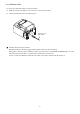
2. Parts Identification and Nomenclature Printer cover Cover open lever Open to replace paper. Do not open while printing. Use this lever to open the printer cover. Power switch Control panel Turns the printer on and off. Features lamps that indicate printer status and a button for operating the printer. FEED button TSP650 POWER ERROR When the printer is online, pressing this button feeds the paper roll. FEED ERROR lamp (red) POWER lamp (green) Lights when the printer is online.
3. Setup 3-1. Connecting the Interface Cable to the PC 3-1-1. Parallel Cable Connect the parallel cable to a parallel port on your PC. 3-1-2. RS-232C Cable Connect the RS-232C cable to a RS-232C port on your PC. 3-1-3. USB Cable Connect the USB cable to a USB port on your PC. 3-1-4. Ethernet Cable Connect the Ethernet cable to a USB port on your PC.
3-2. Connecting the Interface Cable to the Printer Printer cables are not included in the package. Obtain an appropriate cable that complies with the specifications beforehand. Because the appropriate interface cable differs depending on the system that you are connecting the printer to, contact the dealer that you bought the product from if you are unsure about what cable to use. Before connecting or disconnecting an interface cable, be sure to disconnect the AC adapter’s power cord from the outlet.
3-2-2. RS-232C Interface Cable (1) Make sure that the AC adapter’s power cord is not connected to the outlet. (2) Connect the interface cable to the connector on the rear panel of the printer. (3) Tighten the connector screws. RS-232C interface cable 3-2-3. USB Cable To connect a USB cable, follow the procedure given below. (1) Make sure that the AC adapter’s power cord is not connected to the outlet. (2) Connect the USB cable to the USB port.
3-2-4. Ethernet Cable To connect the cable, follow the procedure given below. (1) Make sure that the AC adapter’s power cord is not connected to the outlet. (2) Connect the Ethernet cable to the Ethernet port. Ethernet cable IFBD-HE07 g Link disconnection detection feature The Ethernet interface model is equipped with a link disconnection detection feature.
3-3. Connecting the AC Adapter Note: Before connecting or disconnecting the AC adapter, make sure that the printer and all the devices connected to it are turned off. Then remove the power cord from the outlet. (1) Connect the AC adapter to the power cord. (2) Connect the AC adapter to the connector on the printer. (3) Insert the power cable plug into an AC outlet. CAUTION When disconnecting the cable, take hold of the cable connector to pull it out.
3-4. Turning the Power On Connect the power cord according to the procedure in section 3-3, “Connecting the AC Adapter”. Turn on the power switch, which is on the left side of the printer. The POWER lamp on the control panel will light. Power switch 3-5. Connecting to a Peripheral Device You can connect a peripheral device to the printer using a modular plug. Follow the procedure given below. 1) Make sure that the AC adapter’s power cord is not connected to the outlet.
3-6. Loading a Paper Roll Use a paper roll that complies with the printer specifications. (1) Push the cover open lever, and open the printer cover. Cover open lever (2) Load the paper roll into the printer in the direction indicated by the figure, and pull the leading edge of the paper straight toward you. Paper roll (3) Push on both sides of the rear cover to close it. Note 1: Be careful not to pull the paper out at an angle, because doing so may cause the paper to jam or skew.
3-6-1. Compliant Paper Roll Specifications Paper thickness 53 μm to 85 μm Paper width 79.5 ± 0.5 mm 57.5 ± 0.5 mm External dimensions • Roll diameter Max. f 83 mm • Take up paper roll width +0.5 80 +0.5 - 1 mm / 58 - 1 mm Core inner and outer diameters Inner diameter f 12 ± 1 mm, external diameter f 18 ± 1 mm Printed surface Outer edge of roll Note 1: Do not glue or tape the paper roll and shaft core together. 2: Do not fold the tail end of the paper.
3-6-2. Changing the Paper Width When using 57.5 mm width paper rolls, attach the supplied paper roll guide to the printer. When you change the effective print width (paper roll width), change the printer utility’s memory switch setting. For details, see the printer utility help. (1) Insert the paper roll guide firmly into the slot in the printer labeled "r58" as shown in the figure below. Paper roll guide (2) Secure the paper roll guide in place by pushing the section marked as “A” in the figure.
3-7. Bluetooth Settings (For Bluetooth Interface Models only) RST button PAIR button Indicates the status of the Bluetooth interface. Green (on): Not connected. Green (flashing): Ready to start pairing. Blue (on): Connected. RST PAIR Purple (flashing): Auto connection ON. LED Pair the printer with the master device by following the procedure below. 3-7-1.
3-7-2. Pairing using PIN code Enter the following information in the master device if it does not support SSP, or when otherwise necessary. PIN: 1234 (default) Device name: Star Micronics (default) It is recommended that you change the PIN code for greater security. For details regard changing the PIN code, please see the “Software Manual -Star Bluetooth Utility- ”. 3-7-3.
See the table below for details of Auto Connection setting. Auto Connection ON Auto Connection OFF Reconnecting without changing the parent device After the printer is turned on, it automatically connects to the last parent device that was connected. After turning on the printer, tap this printer's name on the Bluetooth settings screen on the parent device.
3-7-4. Setting up Auto Connection uSetting up from the Main Unit for the TSP650II Note : The following procedure explains how to change the Auto Connection function setting from ON to OFF. If you want to change it from OFF to ON, please follow the same procedure. (1) When paper is loaded in the printer and it is turned on, the [POWER] LED(green) on the front of the printer turns on.
3-7-5. Resetting Bluetooth Settings The PIN code, device name, and other settings can be reset by following the procedure given below. (1) Use a fine pointed pen or other similar object to press and hold the RST button. While holding the RST button, turn the printer's power switch on. (2) The reset process will begin, and the LED at the front of the printer will flash green. When the settings have been reset, the LED will stop flashing.
3-8. Setup Precautions Caution Symbol These symbols are located near the thermal print head. Because the thermal print head is hot immediately after printing, do not touch it. Static electricity can damage the thermal print head. To protect the thermal print head from static electricity, do not touch it. This symbol is located near the cutter. Never touch the cutter blade, as you could injure your fingers. This symbol is located near the peripheral drive connector. Do not connect this to a telephone.
l Do not open the printer covers while the printer is printing or cutting. l Do not pull out paper when the printer cover is closed. l If liquid or foreign objects (such as coins and paper) enter the inside of the printer, turn the power switch off, disconnect the power cord from the AC outlet, and consult the dealer that you bought the product from. Continuing to use the printer may lead to a short-circuit, which may cause electric shock or fire.
4. Attaching the Accessories The following accessories are necessary when mounting the printer to a wall. • Holder plate and two flangeless screws The following accessories are necessary when positioning the printer vertically. • Four rubber feet The following accessories do not necessarily have to be attached. Attach it if necessary. • Switch cover 4-1.
(3) Push the cover open lever, and open the printer cover. (4) Insert the roll paper as shown. Precautions regarding installation CAUTION This caution indicates information that, if ignored, could lead to personal injury or property damage. • Be sure to have qualified personnel install the specified screws and printer to the wall. Star is not responsible for any accidents or injuries that occur as a result of improper installation, misuse, or modifications.
4-2. Attaching the Rubber Feet (1) Ensure that any soiling has been completely wiped off before attaching the rubber feet. (2) Attach the four rubber feet in the positions shown in the figure. 4-3. Switch Cover Installation It is not necessary to install the switch cover. Only install it if it is necessary for you. By installing the switch cover, the following become possible. • Preventing the power switch from being operated by mistake. • Ensuring that other people can not easily operate the power switch.
5. Adjusting the Near-end Sensor Use the following procedure to adjust the near-end sensor so it is compatible with the size of paper roll you are using.
6. Error Indicators 6-1. Recoverable errors Check the recovery conditions. The printer can be recovered while maintaining its current status. Error description Thermal head high temperature detection error POWER ERROR Recovery condition Flashes at 1 second intervals Off The printer recovers automatically when the thermal head cools. Cover open error On On The printer recovers when you close the cover.
7. Preventing and Removing Paper Jams 7-1. Preventing Paper Jams l To avoid paper jams and other problems, feed the paper at least 1 mm (8 dot lines) before printing. l If you want to use the cutter, to avoid paper jams and other problems, we recommend a margin of at least 5 mm from the end of the printed area to the cutting position. l When you set the paper roll into the printer, do not pull out the end of the paper at an angle.
7-3. Releasing the Cutter Lock If the auto cutter locks up, restart the printer by turning the power switch off and then back on. A typical locked cutter will be restored when you restart the printer. If restarting the printer does not release the locked cutter, follow the procedure below. Note 1: Be sure to turn off the printer before performing maintenance on the cutter. 2: When removing jammed paper, be careful not to damage the printer.
8. Maintenance Accumulation of paper dust and dirt may cause the printer to not print portions of characters. To prevent such problems, perform periodic maintenance, such as removing paper dust from the paper transport section and removing the blackened paper dust from the thermal head surface. As a guideline, clean the printer every six months. Note: Turn the printer’s power switch off before performing maintenance. 8-1.
English: Hereby, STAR MICRONICS CO.,LTD. declares that this Wireless Device is in compliance with the essential requirements and other relevant provisions of Directive 1999/5/EC. Deutsch: [German] Hiermit erklärt STAR MICRONICS CO.,LTD., dass sich das Gerät Wireless Device in Übereinstimmung mit den grundlegenden Anforderungen und den übrigen einschlägigen Bestimmungen der Richtlinie 1999/5/EG befindet. Svenska: [Swedish] Härmed intygar STAR MICRONICS CO.,LTD.
STAR MICRONICS CO.,LTD. Head Office 20-10 Nakayoshida, Suruga-ku, Shizuoka-shi, Shizuoka, 422-8654, Japan Tel. + 81-54-263-1111 Fax. + 81-54-263-1057 STAR Quality Technical Center 18-12 Nakayoshida, Suruga-ku, Shizuoka-shi, Shizuoka, 422-8001, Japan Tel. + 81-54-263-1303 Fax.
http://www.starmicronics.