Dot Impact Printer STAR Command Specifications Rev. 0.70 Star Micronics Co., Ltd.
Contents 1. GENERAL DESCRIPTION 2. COMMAND FUNCTION LIST 3.
ESC GS R n1 n2 3-3-7 Download ESC & NUL n1 n2 [m d1 d2 d3 d4 d5 (d6 d7)] n2 - n1 + 1 ESC & m n1 n2 [d1 d2 d3 d4 d5 d6 d7 d8 d9 d10 ....
. CHARACTER CODE TABLE 5. APPENDIX 5-1 Status Specifications 5-1-1 ENQ Command Status 5-1-2 EOT Command Status 5-1-3 Automatic Status 5-1-4 Printer Status Transmission Specification when using Ethernet and Wireless LAN Interfaces 5-2 Expansion Position 5-2-1 7 x 9 Fonts 5-2-2 5 x 9 (2P-1) Fonts 5-2-2 Japanese Character Fonts 6.
Rev. 0.70 1. GENERAL DESCRIPTION This specifications document describes the command specifications for the STAR MODE on dot impact printers. Information contained herein applies to models with the following conditions. • Dot impact printers • Printer head: • Interfaces: • Paper width: • Paper feed minimum pitch: 72 DPI (vertical direction) Parallel/RS-232C/USB/Ethernet/Wireless LAN 3 inch/2.25 inch/1.75 inch 1/144 inch (0.
Rev. 0.70 2.
Rev. 0.
Rev. 0.70 Class Commands Name Others RS CAN DC3 DC1 ESC @ ESC U ESC GS # ESC # ESC ? LF NUL Ring buzzer Cancel print data and initialize commands Printer deselect Select printer Command initialization Select printing direction Set memory switch Set memory switch Reset printer and execute self print Note 1 Kanji characters • Japanese character control commands are ignored on models not installed with Japanese character fonts.
Rev. 0.70 3. COMMAND DETAILS 3-1 Explanation of Terms • Reception buffer The buffer for storing data (reception data) received from the host, as it is called the reception buffer. Reception data is temporarily stored in the reception buffer, then processed sequentially. • Line buffer The buffer for storing image data for printing is called the line buffer. • Line buffer full The state in which the buffer has no more space available is called line buffer full.
Rev. 0.70 3-2 Exception processing 1) Undefined codes Codes from <00>H to <1F>H are targeted.When codes not defined as commands in this region are received, they are discarded. (Ex.) If processing the data string of <30>H<31>H<03>H<32>H<0A>H<33>H, the printer will discard <03>H as an undefined code. 2) Undefined commands When data continuing the codes of ESC and FS are codes not defined as commands, ESC and FS and subsequent codes are discarded. (Ex.
Rev. 0.70 3-3 Standard Command Details 3-3-1 Font style and character set ESC GS t n [Name] [Code] Select code page ASCII ESC Hexadecimal 1B Decimal 27 [Defined Area] [Initial Value] GS 1D 29 t 74 116 n n n n differs depending on the specifications. (See the table below.) Memory switch setting [Function] Specifies the code page according to the value of n. When installed with Japanese, Chinese and Taiwanese language charaters and DBCS setting, this commandis ignored. Specifications Spec. 1 Spec.
Rev. 0.70 ESC R n [Name] [Code] Specify international character set ASCII ESC R n Hexadecimal 1B 52 n Decimal 27 82 n [Defined Area] [Initial Value] 0 ≤ n ≤ 14 n = 64 Memory switch setting [Function] Specifies international characters according to the value of n.
Rev. 0.70 ESC 6 [Name] [Code] Switch to IBM character set #2 ASCII ESC 6 Hexadecimal 1B 36 Decimal 27 54 [Defined Area] [Initial Value] ----- [Function] Switches from IBM character set #1 to #2. The subsequent <80> H to <9F> H codes are handled as character data. When the character code table settings are for the IBM character set #1, this command is ignored. This command is only effective in the standard mode.
Rev. 0.70 ESC M [Name] [Code] Specify 7 x 9 font (half dots) (default) ASCII ESC M Hexadecimal 1B 4D Decimal 27 77 [Defined Area] [Initial Value] ----- [Function] Specifies 7 x 9 (half) dot font. Sets the number of printable digits in one line to [total half dot count/(10 + character right space amount). ESC P [Name] [Code] Specify 5 x 9 font (2P-1) ASCII ESC P Hexadecimal 1B 50 Decimal 27 80 [Defined Area] [Initial Value] ----- [Function] Specifies 5 x 9 (2 pulse = 1) dot fonts.
Rev. 0.70 ESC : [Name] [Code] Specify 5 x 9 font (3P-1) ASCII ESC : Hexadecimal 1B 3A Decimal 27 58 [Defined Area] [Initial Value] ----- [Function] Specifies 5 x 9 (3 pulse = 1) dot fonts. Sets the number of printable digits in one line to [total half dot count/(18 + character right space amount).
Rev. 0.70 3-3-2 SO [Name] [Code] Character Expansion Settings Specify double-wide expanded characters ASCII SO Hexadecimal 0E Decimal 14 [Defined Area] [Initial Value] --Cancel double-wide expanded characters [Function] Prints ANK characters and Kanji characters with characters expanded twice the normal width. This command is equivalent to ESC W n (n = 1).
Rev. 0.70 ESC W n [Name] [Code] Specify/cancel expanded double-wide printing ASCII ESC W n Hexadecimal 1B 57 n Decimal 27 87 n [Defined Area] [Initial Value] n = 0, 1, 48, 49 n = 0 (Horizontal double-wide printing cancelled) [Function] Specifies/cancels horizontal double-wide printing for ANK characters and Kanji characters, according to an n value.
Rev. 0.70 3-3-3 ESC E [Name] [Code] Print mode Select emphasized printing ASCII ESC E Hexadecimal 1B 45 Decimal 27 69 [Defined Area] [Initial Value] --Emphasized printing cancelled. [Function] Specifies emphasized printing for subsequent data. When in emphasized printing, data is printed in two passes. This command is effective for both ANK characters and Kanji characters (prints with four passes for 2 pass Kanji characters, and with 8 passes for 4 pass Kanji characters).
Rev. 0.70 ESC – n [Name] [Code] Specify/cancel underling mode ASCII ESC n Hexadecimal 1B 2D n Decimal 27 45 n [Defined Area] [Initial Value] n = 0, 1, 48, 49 n = 0 (Underline cancelled) [Function] Specifies underline according to the value of n. n 0, 48 1, 49 Function Cancels underline Specifies underline Underlines are applied to the 9th dot of the character. Underlines are not applied to horizontal tabs and to specified horizontal direction positions.
Rev. 0.70 ESC 4 [Name] [Code] Specify white/black inversion and red color printing ASCII ESC 4 Hexadecimal 1B 34 Decimal 27 52 [Defined Area] [Initial Value] --White/black inversion cancelled/black color printing specified [Function] The following shows the details of this command. They vary according to the model. Spec.
Rev. 0.70 ESC GS 4 m n [Name] [Code] Select red/black substitute function [ESC 4/5 setting] ASCII ESC GS 4 m n Hexadecimal 1B 1D 34 m n Decimal 27 29 52 m n [Defined Area] m = 1, 2, 49, 50 When m = 1, 49 n = 0 to 3, 255 When m = 2, 50 n = 0, 2 to 5 When m = 83 n = 0, 1 Memory switch setting [Initial Value] [Function] Selects red/black substitute function Selects characters targeted for adornment with m = 1 (ANK) or m = 2 (Kanji characters), and selects the "4”/ “5” command functions with n.
Rev. 0.70 When m = 83 (“S”) Red/black adornment of ANK space characters (20H). m n Red adornment of ANK space characters (20H). 83 0 Adorn 83 1 Do not adorn This parameter specifies whether to adorn red/black for ANK space characters in red printing mode (black/white inverted). The ANK space characters are limited to ASCII code 20H in this setting. In the character code table, if 7FHex is a space character, 7FHex is a target for this setting. The following is an example of each setting.
Rev. 0.70 SI [Name] [Code] Select upside-down printing ASCII SI Hexadecimal 0F Decimal 15 [Defined Area] [Initial Value] --Upside-down printing cancelled [Function] Specifies upside-down printing This command is enabled only when at the top of the line.Therefore, upside down and right-side up characters cannot both exist in the same line. This command is enabled for following.
Rev. 0.70 ESC RS i n [Name] [Code] Specify/cancel character rotated mode ASCII ESC RS i n Hexadecimal 1B 1E 69 n Decimal 27 30 105 n [Defined Area] [Initial Value] [Function] n 0, 48 1, 49 2, 50 0≤n≤2 48 ≤ n ≤ 50 (“0” ≤ n ≤ “2”) Character rotation cancelled (n = 0) Specifies direction to rotate print (clockwise) or to cancel rotation for subsequent data, according to the n value.
Rev. 0.70 3-3-4 LF [Name] [Code] Line Spacing Line feed ASCII Hexadecimal Decimal LF 0A 10 [Defined Area] [Initial Value] --Set line feed to 1/6 inch [Function] After printing data in the line buffer, paper is fed according to the currently set line feed amount. CR [Name] [Code] Carriage return (Print line feed) ASCII CR Hexadecimal 0D Decimal 13 [Defined Area] [Initial Value] --Set line feed to 1/6 inch [Function] Specifies the function according to the memory switch value.
Rev. 0.70 ESC a n [Name] [Code] Feed paper n lines ASCII ESC Hexadecimal 1B Decimal 27 a 61 97 n n n [Defined Area] [Initial Value] 1 ≤ n ≤ 127 --- [Function] After printing data in the line buffer, paper is fed according to (currently set line feed amount x n). This paper feed amount is unaffected even if there are vertical expanded characters and double high and wide expanded characters in one line.
Rev. 0.70 ESC z 0 [Name] [Code] Set line feed to 1/12 inch ASCII ESC z Hexadecimal 1B 7A Decimal 27 122 0 00 0 Or ESC 1B 27 z 7A 122 “0” 30 48 [Defined Area] [Initial Value] --1/6 inch [Function] Sets subsequent line feed amounts to 1/12 inch. ESC z 1 [Name] [Code] Set line feed to 1/6 inch ASCII ESC z Hexadecimal 1B 7A Decimal 27 122 1 01 1 Or ESC 1B 27 z 7A 122 “1” 31 49 [Defined Area] [Initial Value] --1/6 inch [Function] Sets subsequent line feed amounts to 1/6 inch.
Rev. 0.70 ESC A n [Name] [Code] Define n/72 inch pitch line feed ASCII ESC A n Hexadecimal 1B 41 n Decimal 27 65 n [Defined Area] [Initial Value] 0 ≤ n ≤ 85 n = 12 (1/6 inch line feed) [Function] Defines line feed amount for one line as n/72 inch. To enable this code, ESC 2 (line feed pitch setting) must be sent.
Rev. 0.70 ESC 3 n [Name] [Code] Set line feed to n/216 inch line feed pitch (approximate value) ASCII ESC 3 n Hexadecimal 1B 33 n Decimal 27 51 n [Defined Area] [Initial Value] 0 ≤ n ≤ 255 n = 36 (1/6 inch) [Function] Sets subsequent line feed amounts to a value approximate to n/216 inch. Because the minimum pitch for the paper feed mechanism is 1/144 of an inch, the setting value will be approximated according to the following equation. INT (n x 2/3 + 0.
Rev. 0.70 ESC J n [Name] [Code] Execute n/72 inch paper feed one time ASCII ESC J n Hexadecimal 1B 4A n Decimal 27 74 n [Defined Area] [Initial Value] 1 ≤ n ≤ 255 --- [Function] After printing data in the line buffer, paper is fed n/72 of an inch in the forward paper feed direction. This paper feed amount is unaffected even if there are vertical expanded characters and double high and wide expanded characters in one line. The single line feed amount setting value is not changed by this command.
Rev. 0.70 3-3-5 FF [Name] [Code] Page Control Commands Form feed ASCII Hexadecimal Decimal FF 0C 12 [Defined Area] [Initial Value] ----- [Function] This command performs the following operations after the printer prints the printing data in the line buffer. Operations are set by the memory switch. Memory SW Condition (1) Condition (2) Condition (3) Condition (4) Cutter Model Executes a form feed Feeds paper to the cutting position and performs a full cut. (*1) Executes a form feed.
Rev. 0.70 ESC C n [Name] [Code] Set page length to n lines ASCII ESC C Hexadecimal 1B 43 Decimal 27 67 n n n [Defined Area] [Initial Value] 1 ≤ n ≤ 255 1/6 inch x 42 [Function] This command sets the length of one page to [currently set line feed amount x n] lines The current position is the top position of the page. The page length set using this command is unaffected by changing the form feed amount later. Moving to the top of the page is performed using the FF (form feed) command.
Rev. 0.70 VT [Name] [Code] Feed paper to vertical tab position ASCII VT Hexadecimal 0B Decimal 11 [Defined Area] [Initial Value] ----- [Function] This command performs paper feeds up to the next vertical tab position after the printer prints the data in the line buffer. This command is ignored if there are no tabs set. If a vertical tab is set, and the current position is the same as the vertical tab position, or if it is below that position, it feeds paper to the top of the next page.
Rev. 0.70 ESC N n [Name] [Code] Set bottom margin to n lines ASCII ESC N n Hexadecimal 1B 4E n Decimal 27 78 n [Defined Area] [Initial Value] 0 ≤ n ≤ 255 (Not full page length) n=0 [Function] This command sets the bottom margin position to (current line feed amount x n). Portion of Paper Automatically Fed Page Length Bottom Margin of Line n The current position when setting is effective from the next page when within the bottom margin.
Rev. 0.70 3-3-6 Horizontal Direction Printing Position ESC RS A n [Name] [Code] Set print region ASCII ESC Hexadecimal 1B Decimal 27 RS 1E 30 A 41 65 n n n [Defined Area] Specification 1 Specification 2 0≤n≤3 0≤n≤5 [Initial Value] MSW Setting [Function] After printing data in the line buffer, this sets the printable region in the horizontal direction according to the n value.
Rev. 0.70 ESC l n [Name] [Code] Set left margin ASCII ESC Hexadecimal 1B Decimal 27 l 6C 108 n n n [Defined Area] 0 ≤ n ≤ (right margin -2) ≤ 255 [Initial Setting] n=0 [Function] This command sets the left margin (current ANK character pitch x n) using the left edge as a reference after printing data in the line buffer. The left edge is also the reference for upside-down printing.
Rev. 0.70 ESC Q n [Name] [Code] Set right margin ASCII ESC Hexadecimal 1B Decimal 27 Q 51 81 n n n [Defined Area] [Initial Value] 2 ≤ n ≤ maximum printable digits ≤ 255 Maximum printable digits [Function] This command sets the printable region (current ANK character pitch x n) using the left edge as a reference after printing data in the line buffer.The left edge is also the reference for upside-down printing.
Rev. 0.70 HT [Name] [Code] Move horizontal tab ASCII HT Hexadecimal 09 Decimal 9 [Defined Area] [Initial Value] ----- [Function] Move print position to next horizontal tab position. The current position moves to the next tab position when at the horizontal tab position. This command is ignored with under the following conditions. • When there is no horizontal tab set. • When the current position is the same as the furthest right horizontal tab position or to the right of it.
Rev. 0.70 ESC GS a n [Name] [Code] Specify position alignment ASCII ESC GS Hexadecimal 1B 1D Decimal 27 29 [Defined Area] a 61 97 n n n [Initial Value] 0≤n≤2 48 ≤ n ≤ 50 (“0” ≤ n ≤ “2”) n=0 [Function] This specifies position alignment for all data in one line, in the set print region.
Rev. 0.70 ESC GS A n1 n2 [Name] [Code] Specify absolute position ASCII ESC GS Hexadecimal 1B 1D Decimal 27 29 [Defined Area] [Initial Value] [Function] A 41 65 n1 n1 n1 n2 n2 n2 0 ≤ n1 ≤ 255 0 ≤ n2 ≤ 255 --Moves the printing position to the (n1 + n2 x 256) position based on the left margin. The right margin is also the reference for upside-down printing. This command is ignored if the print region is exceeded. When print data is duplicated, the new print data is overwritten by the old print data.
Rev. 0.
Rev. 0.70 [Ex.
Rev. 0.70 [Ex.
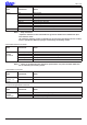
Rev. 0.70 ESC & m n1 n2 [d1 d2 d3 d4 d5 d6 d7 d8 d9 d10 .... ak dk] n2 - n1 + 1 [Name] [Code] Define download characters (vertical 2 byte font) ASCII ESC & m n1 n2 [d1 d2 d3 d4.........dk-1 dk..] n2 - n1 + 1 Hexadecimal 1B 26 m n1 n2 [d1 d2 d3 d4 .........dk-1 dk] n2 - n1 + 1 Decimal 27 38 m n1 n2 [d1 d2 d3 d4 .........
Rev. 0.70 Relationship of character pattern data and print head. [Ex.
Rev. 0.70 [Ex.:] When selecting 9 x 9 fonts, and defining the character to 21H: 7 Dots㩷 㩷 MSB d3㩷 㩷 d13 9 Dots㩷 d1㩷 LSB d2㩷 d4㩷 㩷 d14㩷 ESC & m c1 c2 x d1 d2 d3 d4 d5 d6 d7 d8 d9 d10 d11 d12 d13 d14 d15 d16 d17 d18 Code (Hex.
Rev. 0.70 ESC % N [Name] [Code] Specify/cancel download characters ASCII ESC % n Hexadecimal 1B 25 n Decimal 27 37 n [Defined Area] [Initial Value] n = 0, 1, 48, 49 Cancel download character [Function] Specifies/cancels download character according to n value. n 0, 48 1, 49 Cancel download characters Specify download characters 1. Register download character (ESC & NUL n1 n2 m0 m1 m2…) 2. Specify download characters (ESC % n (n = 1)) 3.
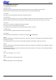
Rev. 0.70 3-3-8 Bit Image Graphics ESC K n NUL d1 d2 … dn [Name] [Code] Standard density bit image ASCII ESC K Hexadecimal 1B 4B Decimal 27 75 [Defined Area] [Initial Value] [Function] n n n NUL 00 0 d1 d1 d1 d2 d2 d2 .. .. .. dn dn dn 1 ≤n ≤total dot count 0 ≤ d ≤ 255 --This command prints bit images with only the data count determined by n. The amount of data that can be printed in one line is limited to the total dot count.
Rev. 0.70 ESC L n1 n2 d1 d2 … dk [Name] [Code] Double density bit image ASCII ESC L Hexadecimal 1B 4C Decimal 27 76 [Defined Area] [Initial Value] [Function] n1 n1 n1 n2 n2 n2 d1 d1 d1 d2 d2 d2 .. .. .. dk dk dk 1 ≤ (n1 + n2 x 256) ≤ total half dot count k = n1 + n2 x 256 0 ≤ d ≤ 255 --This command executes the bit image of a density doubled (half dot printing) for just the data count determined by n1 and n2. The amount of data that can be printed in one line is only the total half-dot count.
Rev. 0.70 ESC ^������������������� �� m ������������������ n1 n2 d1 d2 … dk [Name] [Code] 9/16/18 bit image graphics ASCII ESC ^ Hexadecimal 1B 5E Decimal 27 94 [Defined Area] m m m n1 n1 n1 n2 n2 n2 d1 d1 d1 d2 d2 d2 .. .. .. dk dk dk Spec. 1 0 ≤ m ≤ 1 (“0” ≤ m ≤ “1”) Spec.
Rev. 0.70 The following drawing shows the relationship of the print head needle wires and the data. 1. When m = 0, 1 (9-dot bit image) dn: 1 to 8 pin data MSB Pin Used LSB b7 b6 b5 b4 b3 b2 b1 b0 b7 b6 b5 b4 b3 b2 b1 b0 1 2 3 4 5 6 7 8 9 MSB LSB dn + 1: 9 pin data 2.
Rev. 0.70 3.
Rev. 0.70 3-3-9 Logo ESC FS q n [x11 x12 y11 y12 d1…dk]1…[xn1 xn2 yn1 yn2 d1…dk] n [Name] [Code] Register logo ASCII Hexadecimal Decimal ESC FS q n [x11 x12 y11 y12 d1 .. dk]1 .. [xn1 xn2 yn1 yn2 d1 .. dk]n 1B 1C 71 n [x11 x12 y11 y12 d1 .. dk]1 .. [xn1 xn2 yn1 yn2 d1 .. dk]n 27 28 113 n [x11 x12 y11 y12 d1 .. dk]1 .. [xn1 xn2 yn1 yn2 d1 ..
Rev. 0.
Rev. 0.70 ESC FS p n m [Name] [Code] Print logo ASCII Hexadecimal Decimal ESC 1B 27 FS 1C 28 p 70 112 n n n m m m [Defined Area] 1 ≤ n ≤ 255 (When printing normally) 0≤m≤3 48 ≤ m ≤ 51 (“0” ≤ m ≤ “3”) --Prints the logo of the number n registered using the logo registration command according to the print mode m.
Rev. 0.70 3-3-11 Cutter Control ESC d n [Name] [Code] Paper cut instruction ASCII ESC Hexadecimal 1B Decimal 27 [Defined Area] [Initial Value] [Function] d 64 100 n n n 0≤n≤3 48 ≤ n ≤ 51 (“0” ≤ n ≤ “3”) --This command executes the auto-cut according to the n specification, after printing data in the line buffer. After auto-cutter is executed, the printer considers that position to be the top of the page. n 0, 48 Auto-cutter Full cut at the current position.
Rev. 0.70 3-3-12 External Device Drive ESC BEL n1 n2 [Name] [Code] Set external drive device 1 pulse width ASCII ESC BEL n1 n2 Hexadecimal 1B 07 n1 n2 Decimal 27 7 n1 n2 [Defined Area] [Initial Value] [Function] 1 ≤ n1 ≤ 127 1 ≤ n2 ≤ 127 n1 = 20 (Energizing time: 200 msec) n2 = 20 (Delay time: 200 msec) Sets the energizing and delay times for drive of the external device (such as cash drawers).
Rev. 0.70 BEL [Name] [Code] External device 1 drive instruction ASCII BEL Hexadecimal 07 Decimal 7 [Defined Area] [Initial Value] ----- [Function] Executes the external device drive conditions set according to the ESC BEL (external device drive pulse width setting command). As with other commands, this command temporarily stores data in the data buffer, then executes in the order received. Note External device 1 and external device 2 cannot be executed simultaneously.
Rev. 0.70 SUB [Name] [Code] External device 2 drive instruction (real time) ASCII SUB Hexadecimal 1A Decimal 26 [Defined Area] [Initial Value] ----- [Function] Drives external device 2.The energizing time and delay time are fixed at 200 ms each. The printer executes this command immediately upon reception. This command is the same as the EM command. Note External device 1 and external device 2 cannot be executed simultaneously.
Rev. 0.70 ESC GS EM DC1 m n1 n2 [Name] [Code] Set external buzzer drive pulse condition ASCII ESC GS EM DC1 Hexadecimal 1B 1D 19 11 Decimal 27 29 25 17 [Defined Area] [Initial Value] [Function] m 1, 49 2, 50 m m m n1 n1 n1 n2 n2 n2 1≤m≤2 49 ≤ m ≤ 50 0 ≤ n1 ≤ 255 0 ≤ n2 ≤ 255 n1 = 0, n2 = 0 Set external buzzer drive pulse condition. m specifies the buzzer drive terminal that sets the condition.
Rev. 0.70 ESC GS EM DC2 m n1 n2 [Name] [Code] Execute external buzzer drive ASCII ESC GS EM Hexadecimal 1B 1D 19 Decimal 27 29 25 [Defined Area] [Initial Value] [Function] DC2 12 18 m m m n1 n1 n1 n2 n2 n2 1≤m≤2 49 ≤ m ≤ 50 1 ≤ n1 ≤ 20 n2 = 0 --Repeatedly drives the buzzer according to the ON/OFF conditions set by the external buzzer drive pulse condition command m t1 t2. m specifies the buzzer drive terminal to drive.
Rev. 0.70 3-3-13 Status ENQ [Name] [Code] Inquire ENQ status ASCII ENQ Hexadecimal 05 Decimal 5 [Defined Area] [Initial Value] ----- [Function] This command is effective only when using an interface capable of bi-directional data communications. When this command is received, the printer sends the 1-byte of ENQ status in real time to the host (not taking it from the reception buffer, but executing it immediately upon reception from the host).
Rev. 0.70 ESC ACK SOH [Name] [Code] Inquire status ASCII Hexadecimal Decimal ESC 1B 27 ACK 06 6 SOH 01 1 [Defined Area] [Initial Value] ----- [Function] This command is effective only when using an interface capable of bi-directional data communications. When this command is received, the printer sends the status in real time to the host (not taking it from the reception buffer, but executing it immediately upon reception from the host).
Rev. 0.70 ETB [Name] [Code] Update ETB status (check after printing) ASCII ETB Hexadecimal 17 Decimal 23 [Defined Area] [Initial Value] [Function] --Spec. 1 --Spec. 2 ETB countr = 0 This command is effective only when using an interface capable of bi-directional data communications. Spec. 1 This command waits until all printing is completed (the print motor is stopped), and after printing is completed, the auto status printer status 1-1 (ETB command) becomes 1 (ETB execution completed).
Rev. 0.70 ESC RS E n [Name] [Code] Initialize ASB ETB counter, and ETB status. ASCII ESC RS E n Hexadecimal 1B 1E 45 n Decimal 27 30 69 n [Defined Area] [Initial Value] [Function] n=0 n = 48 (“0”) --Clears the ASB ETB counter to zero and clears the ETB status of the auto-status 1-1.
Rev. 0.70 3-3-14 Kanji Characters (only on models that carry Kanji characters) ESC p [Name] [Code] Specify JIS Japanese character mode (Japanese specifications only) ASCII ESC p Hexadecimal 1B 70 Decimal 27 112 [Defined Area] [Initial Value] --Select JIS Japanese character mode [Function] Specifies JIS Japanese character mode When in JIS Japanese character mode, all character codes are handled as 2 byte Kanji characters (First byte: upper code; second byte: lower code).
Rev. 0.70 ESC $ n [Name] [Code] Specify/cancel JIS Japanese character mode (Japanese specifications only) ASCII ESC $ n Hexadecimal 1B 24 n Decimal 27 36 n [Defined Area] [Initial Value] n = 0, 1, 48, 49 Memory switch setting [Function] Specifies and cancels the shift JIS Japanese character mode.
Rev. 0.70 ESC s n1 n2 [Name] [Code] Set two byte Kanji characters left/right spaces ASCII ESC s n1 n2 Hexadecimal 1B 73 n1 n2 Decimal 27 115 n1 n2 [Defined Area] 0 ≤ n1 ≤ 255 0 ≤ n2 ≤ 255 (However, n1 + n2 + character width ≤ printable region) [Initial Value] • Japanese specifications Memory SW Condition (1) Condition (2) n1 0 0 Memory switch setting n2 2 4 • For China and Taiwan specifications Spec. 1: n = 0, n2 = 4 Spec.
Rev. 0.70 ESC r c1 c2 d1...dk [Name] [Code] Register Chinese download characters ASCII ESC r c1 c2 Hexadecimal 1B 72 c1 c2 Decimal 27 114 c1 c2 [Defined Area] [Initial Value] [Function] d1 d1 d1 .. .. .. dk dk dk 0 ≤ d ≤ 255 k = 32 c1 and c2 differ according to specifications and code type (see table below). All spaces Registers Japanese download characters to c1 and c2 addresses, but the following shows the possible code range. If one has been already registered to an address, it is overwritten.
Rev. 0.70 They are designed as shown below and data is sent sequentially. Horizontal 16 Dots MSB Vertical 16 Dots d1 d3 d5 d7 d9 d11 d13 d15 d17 d19 d21 d23 d25 d27 d29 d31 d2 d4 d6 d8 d10 d12 d14 d16 d18 d20 d22 d24 d26 d28 d30 d32 LSB MSB LSB The font of Chinese download characters is composed of 16 x 16 dot patterns. Bits that correspond to the dots to print are “1,” and the bits that correspond to the dots that are not printed are “0.
Rev. 0.70 ESC u 1 [Name] [Code] Specify 16 x 16 dot [single density] Kanji characters. ASCII ESC u 1 Or ESC u Hexadecimal 1B 75 01 1B 75 Decimal 27 117 1 27 117 “1” 31 149 [Defined Area] [Initial Value] --Specify two-byte 16 x 16 dot (single density) Kanji characters. [Function] Specify 16 x 16 dot [single density] Kanji characters. When two-bytes is selected, they become two-pass characters (state (B) to state (A))Dots continuous horizontally are thinned for printing.
Rev. 0.70 ESC x 1 [Name] [Code] Specify two byte Kanji characters (cancel expanded Kanji characters) ASCII ESC x 1 Or ESC x “1” Hexadecimal 1B 78 01 1B 78 31 Decimal 27 120 1 27 120 49 [Defined Area] [Initial Value] --Specify two-byte 16 x 16 dot (single density) Kanji characters.
Rev. 0.70 ESC w 1 [Name] [Code] Specify two-byte 16 x 16 dot Kanji characters [Single Density] (Default) ASCII ESC w 1 Or ESC w “1” Hexadecimal 1B 77 01 1B 77 31 Decimal 27 119 1 27 119 49 [Defined Area] [Initial Value] --Specify two-byte 16 x 16 dot (single density) Kanji characters.
Rev. 0.70 State (A) 㩷 ESC x 0 Two-byte 16 x 16 Dot Kanji [Single Density] (2-pass Print) ESC u 0 㩷 ESC x 1 ESC u 1 State (B) 㩷 ESC w 0 ESC w 1 ESC x 0 㩷 Two-byte 16 x 16 Dot Kanji [Double Density] (4-pass Print) State (C) 㩷 Double high Kanji 㩷 Print) (Double-high size, 2-pass ESC u 0 㩷 ESC u 1 State (D) 㩷 Double high & wide Kanji ESC x 1 㩷 (Double wide x double high size, 2-pass Print) * See 5.
Rev. 0.70 3-3-15 Others RS [Name] [Code] Ring buzzer ASCII Hexadecimal Decimal RS 1E 30 [Defined Area] [Initial Value] ----- [Function] Issues a short buzzer sound from the printer. CAN [Name] [Code] Cancel print data and initialize commands ASCII CAN Hexadecimal 18 Decimal 24 [Defined Area] [Initial Value] ----- [Function] When the reception buffer and line buffer are cleared, the set commands are initialized.
Rev. 0.70 DC3 [Name] [Code] Printer deselect ASCII Hexadecimal Decimal DC3 13 19 [Defined Area] [Initial Value] --Select printer [Function] Deselects printer. All received data is discarded until the next DC1 (printer select) is received. DC1 [Name] [Code] Select printer ASCII Hexadecimal Decimal DC1 11 17 [Defined Area] [Initial Value] --Select printer [Function] This cancels the deselect state of the DC3 (printer deselect) and selects the printer.
Rev. 0.70 ESC @ [Name] [Code] Command initialization ASCII ESC Hexadecimal 1B Decimal 27 @ 40 64 [Defined Area] [Initial Value] ----- [Function] Initializes each command after printing data in the line buffer. DIPSW and memory switch re-read is not performed. The following shows the specifications that are not initialized by this command.
Rev. 0.
Rev. 0.
Rev. 0.70 ESC ? LF NUL [Name] [Code] Reset printer and execute self print ASCII ESC ? LF NUL Hexadecimal 1B 3F 0A 00 Decimal 27 63 10 0 [Defined Area] [Initial Value] ----- [Function] Hardware resets the printer and executes on self print. After sending this command, the next data is not sent until the printer is online (in a state wherein it can receive data).
Rev. 0.70 3-4 Black Mark Related Commands The Star black mark related commands are to control the top of form (black mark) functions. This commands are effective only when black mark function is valid. 1. Top of form (black mark detection) operation A. Selectable when power is turned on (reset signal is input), when self-print test is completed and by the memory switch.
Rev. 0.70 ESC d n [Name] [Code] Paper cut instruction ASCII ESC Hexadecimal 1B Decimal 27 [Defined Area] [Initial Value] [Function] d 64 100 n n n 0≤n≤3 48 ≤ n ≤ 51 (“0” ≤ n ≤ “3”) --This command executes the auto-cut according to the n specification, after printing data in the line buffer. After auto-cutter is executed, the printer considers that position to be the top of the page. n Auto-cutter 0, 48 Full cut at the current position. This command is ignored on tear-bar models.
Rev. 0.70 FF [Name] [Code] Performs TOF operation ASCII FF Hexadecimal 0C Decimal 12 [Defined Area] [Initial Value] ----- [Function] This command performs the following operations after the printer prints the printing data in the line buffer. Operations are set by the memory switch. Memory SW Cutter Model Tear Bar Model Condition (1) Paper feed to printing start position Paper feed to printing start position Condition (2) Feeds paper to the cutting position and performs a full cut.
Rev. 0.70 ESC FF n1 n2 [Name] [Code] Set top of form amount after detecting black mark ASCII ESC FF n1 n2 Hexadecimal 1B 0C n1 n2 Decimal 27 12 n1 n2 [Defined Area] [Initial Value] 0 ≤ n1 x 256 + n2 ≤ 2047 (however, less that the length between marks) Memory switch setting [Function] This command sets the amount for top of form after black mark detection (n1 x 256 + n2) to steps. (1 step = 1/144 of an inch) The setting value of this command affects the printer initialization command (ESC @).
Rev. 0.70 ESC GS ( F p1 p2 a m n1 n2 [Name] Set top of form amount in black mark control [Code] ASCII Hexadecimal Decimal [Defined Area] [Initial Value] [Function] ESC 1B 27 GS 1D 29 ( 28 40 F 46 70 p1 p1 p1 p2 p2 p2 a a a m m m n1 n1 n1 n2 n2 n2 p1 = 4, p2 = 0 a = 1, 2 m = 0, 48 0 ≤ n1 + n2 x 256 ≤ 1700 (however, less that the length between marks) Memory switch setting Set top of form position (printing start position and cutting position) when using black mark control.
Rev. 0.70 ESC RS m n [Name] [Code] Enable, disable black mark detection ASCII ESC RS m n Hexadecimal 1B 1E 6D n Decimal 27 30 109 n [Defined Area] [Initial Value] n = 0, 1, 2, 48, 49, 50 Memory SW [Function] Switchest to enable/disable black mark (BM) detection control When switching the setting, operations are the same as when switching to enable/disable using the memory switch. (However, that excludes the TOF operation that occurs when the power is turned ON.
Rev. 0.70 3-5 USB Related Commands The following commands control USB interface functions.
Rev. 0.70 3-6 2-Color Printing Command Details ESC RS C n [Name] [Code] Select/cancel 2-color printing mode ASCII ESC RS C Hexadecimal 1B 1E 43 Decimal 27 30 67 [Defined Area] [Initial Value] [Function] n 0, 48 n n n 0≤n≤1 48 ≤ n ≤ 49 (“0” ≤ n ≤ “1”) DIP switch Select/cancel 2-color printing mode Cancel 2-color printing mode When in two-color print mode, this command cancels 2-color printing mode. This command is ignored when the 2-color print mode is already cancelled.
Rev. 0.70 ESC 4 [Name] [Code] Specify white/black inversion and red color printing ASCII ESC 4 Hexadecimal 1B 34 Decimal 27 52 [Defined Area] [Initial Value] --White/black inversion cancelled/black color printing specified [Function] The following shows the details of this command. They vary according to the model. Spec.
Rev. 0.70 4.
Rev. 0.70 5. APPENDIX 5-1 Status Specifications This function is effective only when using an interface capable of bi-directional data communications. Refer to your printer’s product specification manual to verify if the interface cable on the printer you use is capable of bi-directional data communications. 5-1-1 ENQ Command Status This status is the one the printer transmits using the ENQ command.
Rev. 0.70 5-1-3 Automatic Status Auto status is a group of states that are automatically returned from the printer to the host when the printer’s status has changed.Automatic status is composed of “Header 1,” “Header 2” and “plurality of bytes of the printer status and is continuously returned to the host.The host always uses an identifying method to identify the data for every byte received.
Rev. 0.70 2. Header 2 Header 2 is the 1 byte length information transmitted from the second byte of the auto status.The table below shows the composition of the Header 2. Header 2 represents the auto status version (called automatic status version below) using bit 1 to bit 3 and bit 5. For reference, the table below shows the relationship of actual version bytes and the Header 2.
Rev. 0.70 3. Printer Status Printer status is the status of the printer sent from the 3rd byte of the automatic status. For the printer status, (the number of bytes added in Header 1 minus two) is returned. Printer status is always updated or new information. (No log exists.) The following shows the composition of the status.
Rev. 0.
Rev. 0.70 4. Cautions Do not use ENQ, EOT, ESC, ACK and SOH when auto status is valid.Invalidate the automatic status in advance using the DIPSW (memory switch) or the ESC RS a n command to query these. 5. How to Identify Statuses Command/Functions XON XOFF ENQ EOT Auto Status (Header 1) Auto Status (Other than Header 1) bit 7 0 0 * * 0 bit 6 0 0 * * * bit 5 0 0 * * * 0 * * Status bit 4 bit 3 1 0 1 0 0 * 1 * 0 * 0 * 0 = fixed at “0” bits/1 = fixed at “1” bits/* = variable bits.
Rev. 0.70 5-1-4 Printer Status Transmission Specification when using Ethernet and Wireless LAN Interfaces The following explains the printer status transmission specification when using Ethernet and wireless LAN interfaces.
Rev. 0.70 B. Classification character 1 (1 Byte) Sends “:” (3AH). C. Data Type (1byte) Indicates the data type of the printer status, and sends “B” (binary type, 42H). D. Status length (2 bytes) 2 byte value indicating byte count of printer status E. Printer status (variable) Status sent by printer The content of the status differs according to the cause. Refer to Commands That are Factors, and Automatic Status for details on the content of the status. F.
Rev. 0.70 5-2 Expansion Position 5-2-1 7 x 9 Fonts Head Pin No. Normal Dot Head Pin 㩷No. Half Dot 㩷 㩷 #1 #2 #3 #4 #5 #6 #7 #8 #9 #1 #2 #3 #4 #5 #6 #7 #8 #9 #1 #2 #3 #4 #5 #6 #7 #8 #9 Normal 7 x 9 5-2-2 Double high 7 x 9 Bit Image 5 x 9 (2P-1) Fonts Head Pin No.㩷 Normal Dot Head Pin No.
Rev. 0.70 5-2-2 Japanese Character Fonts Normal Dot㩷 Half Dot 㩷 Head Pin No.㩷 #1 #1 #2 #2 #3 #3 #4 #4 #5 #5 #6 #6 #7 #7 #8 #8 #9 #9 ANK 7 x 9 #1 #2 1/144 Inch㩷 1/72 Inch 㩷 Head Pin No.㩷 #3 #4 #5 #6 #7 #8 #9 Two-byte Kanji 16 x 16 [Single Density] First Pass First Pass Second Pass Normal Dot Half Dot Head Pin No.
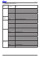
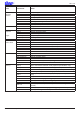
Rev. 0.70 6. SPECIAL APPENDIX COMMAND LIST BY MODEL • Standard Commands Class Font Style and Character Set Character Expansion Settings Print Modes Line Spacing Page Control Commands Model Name BD500 SP500 BD100 SP2000 ESC GS t ○ Spec. 1 ○ Spec. 1 ○ Spec. 1 ○ Spec. 1 ○ Spec.
Rev. 0.
Rev. 0.
OVERSEAS SUBSIDIARY COMPANIES STAR MICRONICS AMERICA, INC. 1150 King Georges Post Road, Edison, NJ 08837-3729 U.S.A. Tel: (int+1)-732-623-5555, Fax: (int+1)-732-623-5590 ELECTRONIC PRODUCTS DIVISION STAR MICRONICS CO., LTD. 536 Nanatsushinya, Shimizu-ku, Shizuoka, 424-0066 Japan Tel: (int+81)-54-347-0112, Fax: (int+81)-54-347-0709 Please access the following URL http://www.star-m.jp/eng/dl/dl02.htm for the latest revision of the manual. STAR MICRONICS U.K. LTD.