USER’S MANUAL LC-1511 LC-1521 DOT MATRIX PRINTERS HA15 80825072
Federal Communications Commission Radio Frequency Interference Statement The 120V version equipment has been tested and found to comply with the limits for a Class B digital device, pursuant to Part 15 of FCC Rules. These limits are designed to provide reasonable protection against harmful interference in a residential installation.
Trademark acknowledgments FR-15, IS-8H192, IS-32H768, LC-1511, LC-1521, PT-15HA, SF-15HA, SPC-8K, XR-1500, XR-1520, ZA-250: Star Micronics Co. Ltd. EX-800, FX-1170: Seiko Epson Corporation IBM PC, IBM Proprinter, IBM Proprinter2, IBM Proprinter 3, OS/2: International Business Machines Corporation. TrueType: Apple Computer Inc. MS-DOS, Microsoft Windows, Windows 3.1, Windows 95: Microsoft Corporation Notice • All rights reserved.
About this manual This manual describes how to set up, use, and care for the Star LC-1511 and LC-1521 printers. The following is a list of what you can expect to find in each chapter.
Contents Chapter 1: Printer Setup ... 1 Choosing a place for the printer ... 1 Unpacking the printer ... 2 General guide ... 3 Opening the front cover ... 4 Removing the protective materials ... 4 Installing the platen knob ... 6 Installing the ribbon cassette ... 6 Removing the ribbon cassette ... 8 Installing the paper guide ... 9 Standing up the paper guide ... 10 Connecting to a power outlet and turning power on and off ... 11 Loading fanfold paper ... 12 Printing on fanfold paper ...
Chapter 3: Using the EDS Mode ... 28 About EDS Mode settings ... 28 Entering the EDS Mode ... 28 Selecting a bank ... 29 Selecting a switch ... 29 Changing a switch setting ... 29 Printing the current switch settings ... 30 Checking the settings of switches in a bank ... 30 Exiting the EDS Mode ... 30 EDS Mode Settings ... 31 Chapter 4: User Setup Utility ... 40 Installing the User Setup Utility ... 40 Starting the User Setup Utility ... 41 Changing the General, Font, Paper and Adjust Settings ...
Chapter 8: Using the Printer with MS-DOS ... 61 Setting up for printing with MS-DOS ... 61 Chapter 9: Paper Handling ... 62 Selecting paper types ... 62 Adjusting for paper thickness ... 63 Automatic fanfold feeding ... 64 Manual sheet feeding ... 64 Clearing paper jams ... 65 Chapter 10: Optional Accessories ... 66 Automatic Sheet Feeder (SF-15HA) ... 66 Pull Tractor Unit (PT-15HA) ... 67 Serial Interface Unit (IS-8H192 and IS-32H768) ... 67 Serial-to-Parallel Converter (SPC-8K) ...
1 Chapter 1: Printer Setup This chapter contains important information on setting up your printer. Be sure to read this chapter carefully before using the printer for the first time.
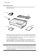
2 Printer Setup Unpacking the printer Check to make sure that the carton contains each of the items shown in the following illustration. Ribbon cassette Paper guide Platen knob Printer User’s manual 3.5"Floppy disk If anything is missing, contact the store where you bought the printer and ask them to supply the missing part. Note that it is a good idea to keep the original box and all the packing materials just in case you need to pack the printer up again and send it somewhere at a later date.
General guide General guide The following illustrations show the major components of your printer.
4 Printer Setup Opening the front cover ❏ Lift up on the front cover and swing it open until it stops. Tear assist edge ❏ To close the front cover, simply lower it back into place. Caution! The tear assist edge is rather sharp. Take care to avoid injuring your hands. Note: You can completely remove the front cover from the printer or you can stand it up. You should normally leave the front cover closed, because it protects against objects getting into the printer, and it cuts down on printer noise.
Removing the protective materials 5 ❏ Remove the two white pieces of packing from inside the printer as shown in the illustration. A piece of cardboard is inserted into the printer to protect components during shipping. Be sure to remove it before using the printer. ❏ Open the front cover. ❏ Remove the cardboard from the inside of the front cover as shown in the illustration. In addition, remove the cardboard from the back of the paper guide. ❏ Remove the tape.
6 Printer Setup Installing the platen knob The platen knob is packed into a recess in the packaging material. ❏ Install the knob on the shaft located inside the large hole on the left side of the printer. Make sure that the two splines of the platen shaft inside the printer fit into the slots inside the knob’s spindle. Press the knob carefully but firmly into place as far as it will go. Installing the ribbon cassette ❏ Make sure the printer is unplugged from its power outlet.
Installing the ribbon cassette 7 ❏ Rotate the knob on the ribbon cassette clockwise to take up any slack in the ribbon. Tension knob ❏ By hand, move the cartridge holder to the left side where there is a cut-out ❏ in the top guide to allow easy installation and removal of the ribbon cassette. Carefully place the cassette onto the cartridge holder making sure that the spindle of the holder fits into the socket on the bottom of the cassette.
8 Printer Setup ❏ While guiding the ribbon between the print head and print head shield, press down gently but firmly on the cartridge until the side tabs snap securely into place. Print head shield Ribbon Print head ❏ Rotate the knob on the cassette again to take up any slack. ❏ Replace the front cover of the printer. Important! Printing that is poor quality or too light is almost always due to a ribbon that is simply worn out or “used up.
Installing the paper guide 9 ❏ Open the front cover of the printer. ❏ By hand, move the cartridge holder to the left side where there is a cutout in the top guide to allow easy installation and removal of the ribbon cassette. ❏ Using your thumb and forefinger to squeeze the two tabs on the ribbon ❏ cassette towards the center, carefully remove the cassette from the holder. Use the procedure under “Installing the ribbon cassette” on page 6 to install a new cassette.
10 Printer Setup Standing up the paper guide ❏ You can move the paper guide so that it is at angles of 50 or 70 as shown in the illustrations below. The correct angle depends on the type of the paper you are using. Paper guide Paper guide 50° 50-degree angle (Fanfold paper) 70° 70-degree angle (Cut-sheet paper) The following table shows the correct angle to use for each type.
Connecting to a power outlet and turning power on and off 11 Connecting to a power outlet and turning power on and off ❏ Plug the power cord of the printer into a standard power outlet whose voltage matches the power rating noted on the label affixed to the bottom of your printer. Caution! If the voltage marked on the bottom of your printer does not match the voltage from the outlet you are using, do not plug in the power cord. Contact your dealer for assistance.
12 Printer Setup Loading fanfold paper This section tells you how to load fanfold paper. Note that you can also use cutsheet paper. For details on using other types of paper, see “Paper Handling” on page 62 of this manual. ❏ Remove the paper guide from the printer. ❏ Make sure printer power is turned off. ❏ Set the release lever to the fanfold position.
Loading fanfold paper 13 ❏ Swing the rear cover back and down until it stops. Metal edge Note: You can also completely remove the rear cover by simply pulling it away from the back of the printer after you open it. Caution! The metal edge of the cover is rather sharp. Take care to avoid injuring your hands when handling it. ❏ Pass the fanfold paper through the space between the printer case and the rear cover.
14 Printer Setup ❏ Close the tractor covers. At this point you can make final adjustments to the paper position by releasing the gray levers and moving the tractors. The paper should lie flat with no buckling or bulging (tractors too close) or no stretching or elongation of the holes (tractors too far apart). After making these adjustments, be sure that you re-lock the tractors by pushing the gray levers back into their original positions.
Loading fanfold paper 15 ❏ Install the paper guide so that it is standing up (at a 50-degree angle) as shown on page 10. In this position, the paper guide keeps the printed paper separate from the unprinted paper. Then slide the right and left paper guides apart so they do not interfere with the fanfold paper feeding. ❏ Turn on the printer. ❏ The printer will beep a number of times to indicate that paper is not loaded properly.
16 Printer Setup Printing on fanfold paper When printing on fanfold paper, take care not to print too close to the perforations that separate each sheet. The following shows the recommended print area for fanfold paper, cut-sheet paper and label paper. Fanfold paper Cut-sheet paper 4 mm (0.16") 4 mm (0.16") 5 mm (0.2") 5 mm (0.2") First page Perforation 25.4 mm (1") 8 mm (0.31") 25.4 mm (1") 18 mm (0.7") 18 mm (0.7") Label C Perforation C 25.4 mm (1") Perforation 2.54 mm (0.1") min.
Parking fanfold paper 17 Parking fanfold paper It is not necessary to remove fanfold paper currently loaded in the printer in order to print on cut-sheet paper. Instead, simply use the following procedure to park the fanfold paper. ❏ Tear off the paper at a perforation so there is no more than half a page ❏ ❏ ❏ ❏ sticking out of the front cover of the printer. If necessary, you can press the control panel’s ON LINE button to put the printer off-line.
18 Printer Setup Using the tear-off function The following procedure makes it easy to tear off fanfold paper. ❏ Check to make sure that the printer is on-line. ❏ Press the FORM FEED button to perform the long tear-off operation, or ❏ press the LINE FEED button to perform the short tear-off operation. The long tear-off operation causes the paper to be fed automatically so the tear assist edge of the printer cover is aligned with the paper’s next perforation.
Connecting to your computer 19 ❏ Plug one end of the parallel cable into the parallel port of your computer. ❏ The parallel port should be labeled “Printer,” “Parallel,” “PRN,” “LPT1,” or something similar. Plug the other end of the parallel cable into the socket on the side of the printer and secure it in place with the clips.
20 Chapter 2: Control Panel Operations The control panel gives you push-button control over the printer’s operations. It includes indicator lights, which tell you the current status of the printer at a glance.
Selecting a font 21 Selecting a font ❏ Make sure the printer is off-line (ON LINE indicator is not lit). ❏ Press FONT to change the font selection. An indicator lights to the left of the name of the font that is currently selected. HS-Draft is selected when all font indicators on the LC-1521 are off.
22 Control Panel Operations Setting the character pitch The character pitch setting controls how many characters are printed per inch. Use the following procedure to select the pitch you want. ❏ Make sure the printer is off-line (ON LINE indicator is not lit). ❏ Press PITCH to change the pitch selection. The following shows the meanings of the indicators that light on the control panel when you press PITCH.
Line feed 23 Line feed ❏ Make sure the printer is off-line (ON LINE indicator is not lit). ❏ Press LINE FEED once to feed paper one line. Holding down LINE FEED continually feeds paper, one line at a time, until you release the button. Paper eject (cut-sheet paper) ❏ Make sure the printer is off-line (ON LINE indicator is not lit). ❏ Press SET/EJECT/PARK to eject the paper. ❏ After the paper is ejected, the printer will beep and the POWER indicator will flash to indicate there is no paper in the printer.
24 Control Panel Operations Setting the top of form position The current position of paper loaded in the printer is automatically set as the top of the page whenever you turn power on. You can also use the following procedure at any time to specify a different position as the top of the page. ❏ Make sure the printer is off-line (ON LINE indicator is not lit).
Changing the auto load position 25 ❏ Make sure the printer is on-line (ON LINE indicator is lit). ❏ Press SET/EJECT/PARK, to toggle between the Quiet Print Mode and normal printing. The printer emits one short beeps when the Quiet Print Mode is selected, and two short beep when normal printing is selected. Changing the auto load position Normally the printer automatically feeds paper to a standard position (1/6-inch from the top of the paper). This is called the auto load position.
26 Control Panel Operations Saving a macro Normally, any settings you make on the control panel are cleared when you turn the printer off. Use the following procedure to save the current control panel settings so that they are used whenever you turn the printer on. ❏ Make the control panel settings you want. ❏ Use ON LINE to put the printer off-line (ON LINE indicator is not lit). ❏ Hold down FONT and then PITCH. Keep both buttons held down until the ❏ printer beeps twice.
27 Initializing the printer The following procedure initializes the printer to its power-on settings. If you have control panel settings stored in memory, this procedure sets up the printer using them. ❏ Use ON LINE to take the printer off line (ON LINE indicator is not lit). ❏ Hold down FONT and then FORM FEED. Keep both buttons held down until the printer beeps once (indicating the printer buffer is cleared) and then beeps again three times, which indicates that the printer is reset.
28 Chapter 3: Using the EDS Mode The letters “EDS” stand for “Electronic DIP Switches.” Just like the small DIP switches that are used by many computers, printers, and other devices, the EDS mode lets you configure the printer so that it matches your system and software needs. This chapter describes how to enter the printer’s EDS Mode and provides details about available settings and how to change them. All switch settings, except for F-2, are ON when the printer is shipped from the factory.
Selecting a bank 29 Selecting a bank ❏ While in the EDS Mode, use the control panel’s BANK button to select a bank. When the BANK indicator flashes it indicates the current bank selected. Lit Indicator Selected Bank A1 A B2 B C3 C D4 D E5 E F6 F Selecting a switch ❏ While in the EDS Mode, use the control panel’s SWITCH button to select a bank switch. When the SW indicator flashes it indicates the current switch selected.
30 Using the EDS Mode Printing the current switch settings ❏ In the EDS Mode, press the control panel’s PRINT button to print out the current switch settings. Asterisks on the printout show whether a switch is turned on or off. Checking the settings of switches in a bank ❏ After selecting a bank, press the control panel’s STATUS button to view the status of each switch in that bank. The control panel’s font indicator is lit when the switch is on, and is not lit when the switch is off.
EDS Mode Settings 31 EDS Mode Settings The following details all of the settings you can program in the EDS Mode. You can print out a detailed overview of all the settings by performing a test of the printer (page 70). BANK A Switch 1: Emulation Selects Standard emulation (ON) or IBM emulation (OFF). Standard emulation causes the printer to act like the Epson ESC/P (9-pin), while IBM emulation makes it act like the IBM Proprinter III.
32 Using the EDS Mode Switch 6: Multi-Part Mode Specifies whether the printer’s Multi-Part Mode is enabled (OFF) or disabled (ON). When the Multi-Part Mode is enabled (OFF), the impact of the print head is increased, but head life is decreased. Enable the Multi-Part Mode when printing on four to five-ply paper. Disable the Multi-Part Mode when printing on 1 to 3-ply paper. BANK B Switch 1: Graphics Direction Selects uni-directional (OFF) or bi-directional (ON) printing for graphics.
EDS Mode Settings 33 BANK C Switches 1, 2: Print Mode Turn these switches on or off to select the print mode you want to use. Print Mode SW1 SW2 Draft ON ON NLQ ON OFF HS-Draft* OFF ON * LC-1521 only. Not used with LC-1511. Switches 3, 4, 5: Print Pitch Turn these switches on or off to form the pattern that matches the print pitch setting you want to make.
34 Using the EDS Mode BANK D Switches 1, 2, 3, 4: Page Length Turn these switches on or off to form the pattern that matches the Page Length setting you want to use. Page Length SW1 SW2 SW3 SW4 11”/Letter ON ON ON ON 8” OFF ON ON ON 11.7”/A4 ON OFF ON ON 12” OFF OFF ON ON 8.5”/Letter ON ON OFF ON 14”/Legal OFF ON OFF ON 10.5”/Executive ON OFF OFF ON 7.25”/Executive OFF OFF OFF ON 3.5” ON ON ON OFF 5.
EDS Mode Settings Code Page SW1 SW2 SW3 SW4 SW5 #437 IBM-PC ON ON ON ON ON #850 Multi-lingual OFF ON ON ON ON #860 Portuguese ON OFF ON ON ON #861 Icelandic OFF OFF ON ON ON #863 Canadian French ON ON OFF ON ON #865 Nordic OFF ON OFF ON ON #866 Russian ON OFF OFF ON ON #3840 IBM-Russian OFF OFF OFF ON ON #3841 Gost-Russian ON ON ON OFF ON #3843 Polish OFF ON ON OFF ON #3844 CS2 ON OFF ON OFF ON #3845 Hungarian OFF OFF ON OFF ON #
36 Using the EDS Mode A code page is the set of symbols and characters that your printer can print. Your printer converts ASCII hexadecimal data according to a code page to print symbols and characters. By supporting different code pages, the printer can print in a variety of different languages. The following table shows detailed information about code pages.
EDS Mode Settings Code Page Name #928 Greek #2001 Country 37 Remarks Greece For UNIX Lithuanian-KBL Lithuania Commonly used for DOS #772 Lithuanian Lithuania New standard #774 Lithuanian Lithuania #3001 Estonian-1 Estonia #3002 Estonian-2 Estonia #3011 Latvian-1 Latvia #3012 Latvian-2 Latvia #3021 Bulgarian Bulgaria #3031 Hebrew Israel #3041 Maltese Malta Most often used Government standard
38 Using the EDS Mode If your EDS settings specify Standard emulation (Bank A, Switch 1 ON) with the italic character table (Bank A, Switch 2 OFF), use the Bank E switches to select the international character set you want to use. This setting determines the assignment of 14 character codes in the Standard Italic character set. International Character Set SW1 SW2 SW3 SW4 SW5 U.S.A.
EDS Mode Settings 39 BANK F Switches 1, 2, 3, 4, 5: NLQ Font Selection Turn these switches on or off to form the pattern that identifies the font you want to use for NLQ printing. Font SW1 SW2 SW3 SW4 SW5 Roman ON ON ON ON ON Sanserif OFF ON ON ON ON Courier ON OFF ON ON ON Prestige OFF OFF ON ON ON Orator OFF OFF OFF ON ON Note: Bank C switches 1 and 2 need to be in the correct positions before the above setting will have any effect.
40 Chapter 4: User Setup Utility The User Setup Utility is included on the floppy disk that comes with the printer. It allows you to change the EDS settings of the printer from your computer. To run the User Setup Utility, you need an IBM-compatible computer running PC-DOS or MS-DOS. The computer must be equipped with a 3.5″ floppy drive and a hard disk drive.
Starting the User Setup Utility 41 Setting for Install Language: English Printer Type: LC-1511 Install Directory: c:\star F1=Install F2=Cancel ❏ Pull down the list of available languages under Language: and double❏ ❏ ❏ ❏ click the one you want to use. Pull down the list of available printers under Printer Type: and doubleclick on the one you want to use. For this printer you should select LC-1511 or LC-1521. Click the Install Directory: box to change it into an input box.
42 User Setup Utility Help F1 Exit F2 Emulation Standard RAM usage Input Buffer Quiet mode Disabled File F3 * * General F4 Font F5 Paper F6 Adjust F7 Port F8 General Graphic Direction Bi-direction * CR Centering Position Long * * When you start the User Setup Utility, it reads and displays the last settings that were sent to the printer by the utility. Note: The utility does not read the settings from the printer.
Adjusting the dot alignment 43 To select a setting box ❏ Click on the box you want to select or move to by using your keyboard’s Tab or arrow keys. The currently selected setting box is highlighted on the screen. To change a setting ❏ After you select a setting box, click on the box or press Enter to pull down a list of available settings. ❏ Select the setting you want to use in the list by double-clicking on it, or by moving to it with the arrow keys and pressing Enter.
44 User Setup Utility Changing the printer port ❏ Click on Port or press the F8 function key. Port Lpt1: Com1: Com2: ❏ Select the port you want to use by double-clicking on it, or by moving to it with the arrow keys and pressing Enter. Saving setup data in a configuration file ❏ To save setup data in a configuration file so you can recall it later, click on ❏ File or press the F3 function key.
Importing setup data from a configuration file 45 Importing setup data from a configuration file ❏ Click on File or press the F3 function key. ❏ Select Load from the menu that drops down by double-clicking on it, or by moving the highlighting to it with the arrow keys and pressing Enter. Load file File C:\STAR\*.cfg ..
1995-06-15 DEFAULT .CFG 1995-06-15 PREVIOUS.46 Chapter 5: Using the Printer with Windows 3.1 This chapter contains specific information you need to know when using the printer with Microsoft Windows 3.1 or later. It also tells you how to install the printer driver on your computer so that it can control the printer correctly. In this chapter, you will learn about: ❏ ❏ ❏ ❏ ❏ How to set up for printing with Microsoft Windows 3.
Setting up for printing with Microsoft Windows 3.1 ❏ ❏ ❏ ❏ 47 Click Add and the dialog box will expand to show a List of Printers. In the List of Printers: box, select Install Unlisted or Updated Printer. Click Install. This causes the Install Driver dialog box to appear, which instructs you to insert the disk that contains the printer driver file. ❏ Click Browse. ❏ In the Directories: list, select WIN 31. ❏ Click on the language you want to use and then click OK.
48 Using the Printer with Windows 3.1 ❏ In the List of Printers: box of the Add Unlisted or Updated Printer ❏ ❏ dialog box, select the Star printer driver and then click OK. This causes the Printers dialog box to appear. The STAR printer is now listed in the Installed Printers: list. Double-click on the name of the printer model you just installed to select it as the default printer. Click Close to close the Printers dialog box.
Printing a document 49 ❏ From this window you select buttons that let you control a wide variety of ❏ ❏ printer setup parameters. This manual does not include any information about how to do this because everything you need to know is included in an on-line manual that tells you how to use all the buttons and menus that appear. To view the on-line manual, click on the Help button. After the printer is set up the way you want it, click on OK.
50 Using the Printer with Windows 3.1 Note: The actual appearance of the Print window may differ somewhat depending on the application you are using. Use this window to specify the range of the pages to be printed, the quality of the printing (in dots per inch), and the number of copies you want to print. Note also that there are boxes that you can select to specify printing to a file or collating (printing from back to front). You can change the printer setup by clicking on the Setup button.
Selecting fonts in Windows applications 51 ❏ Insert the disk that contains the fonts into one of your computer’s disk ❏ ❏ ❏ drives. This explanation assumes you are using a drive named “A:”, but you could use any drive. Just remember to change the “A:” in the following steps to the name of the drive you are using. Select the letter that represents the drive where the floppy disk is installed. When you do, the names of all the fonts on the disk appear in the List of Fonts window.
52 Chapter 6: Using the printer with Windows 95 This chapter describes how to use the printer with Microsoft Windows 95. The following topics are covered: ❏ ❏ ❏ ❏ Setting up the printer in Windows 95 Preparing for printing Printing a document Installing the TrueType fonts Note: The file “readme.txt” on the floppy disk contains any late-breaking information that has been made available since this manual was printed.
Setting up the printer in Windows 95 53 ❏ When the above window is displayed, make sure the Local printer radio button is checked. Then click on the Next button twice, and click on the Back button. ❏ Click on the Have Disk button. ❏ Insert the disk with the printer driver file on it into the floppy disk drive. ❏ Make sure that the drive’s name (“A:” or “B:”) is displayed in the field named Copy manufacturer’s files from:.
54 Using the printer with Windows 95 ❏ Select the language or language group you want to use by clicking on it. ❏ Select the printer model name (“Star LC-1511” or “Star LC-1521”) by clicking on it and then click on the Next button. ❏ Select the printer port to which the printer is connected by clicking on it (usually “LPT1”). Click on the Next button. ❏ Change the printer name if you want.
Preparing to print 55 ❏ Click on the Next button. ❏ Select whether to print out a test page by clicking on the appropriate radio button. ❏ Click on the Finish button. ❏ If a message appears requesting you to insert the Windows 95 CD-ROM, insert it into the CD-ROM drive and click on the OK button. ❏ If a message appears saying that the printer driver file LC15X1.
56 Using the printer with Windows 95 ❏ Double-click on the icon bearing the name of the printer (Star LC-1511 or ❏ ❏ ❏ Star LC-1521) in the Printers window. A window appears listing any documents that are currently being printed on the printer. Click on the Printer menu. To set the printer as the default printer, click on the Set As Default command so that a tick mark appears in the check box. This denotes that the selected printer is the default printer.
Printing a document 57 Printing a document Windows 95 applications always print to the currently selected default printer. If you want to change the default printer, refer to the previous section, Preparing to print. To print from any Windows 95 application, proceed as follows:. ❏ Click on the application’s File menu. ❏ Click on the Print command. Note: The actual appearance of the Print window may differ somewhat depending on the application you are using.
58 Using the printer with Windows 95 Installing TrueType fonts To install the TrueType fonts that are on the floppy disk accompanying this printer, follow the procedure below. ❏ Insert the disk in your computer’s floppy disk drive. ❏ Click on the Start button in the bottom lefthand corner of the screen. ❏ Select Settings. ❏ Release the mouse button on Control Panel. ❏ Double-click on the Fonts folder. The currently-installed font files are displayed. ❏ Click on the Files menu.
59 Chapter 7: Using the Printer with OS/2 Warp This chapter contains specific information about using the printer with IBM OS/2 Warp. It also shows you how to install the printer driver on your computer so you can control the printer. By reading this chapter, you will learn: ❏ How to set up for printing with IBM OS/2 Warp ❏ How to prepare for printing ❏ How to print a document Important! See the “readme. txt” file for important information that became available after this documentation was printed.
60 Using the Printer with OS/2 Warp Getting ready to print There are several steps to set up the printer before using it. You must select the printer driver, and specify the source, size, and orientation of the paper. Use the following procedure to make these selections. Note: You do not need to select the printer driver and paper specifications each time you print, but only if you want to change any of your previous settings. ❏ ❏ ❏ ❏ ❏ ❏ ❏ Point to the printer object. Click mouse button 2.
61 Chapter 8: Using the Printer with MS-DOS This chapter contains information about how to use the printer with applications software running under MS-DOS. In this chapter, you will learn about: ❏ How to set up for printing with MS-DOS Setting up for printing with MS-DOS To print from an application running under MS-DOS, you must first select the printer from within the application. Typically, the program will feature an INSTALL or SETUP command for selection of printers.
62 Chapter 9: Paper Handling Your printer is designed to print on a variety of paper types. This chapter tells you everything you need to know about paper, and how to set the printer up for manual paper feed. In this chapter, you will learn about: ❏ ❏ ❏ ❏ Selecting the best type of paper Adjusting for paper thickness Manual sheet feeding Clearing paper jams Selecting paper types Use the following information when selecting paper. Cut-Sheet Paper (Manual Feed) Width: 7.0″ to 16.
Adjusting for paper thickness 63 Labels Backing sheet: 4.5″ to 16.5″ / 114 to 419mm Thickness Backing sheet: 0.00276″ to 0.0035″ / 0.07 to 0.09mm Total: 0.0075″ / 0.19mm • Use labels under normal temperature and humidity conditions only. Adjusting for paper thickness Paper comes in different weights, normally expressed as gsm (grams per square meter) or lbs (pounds). Some forms paper also have multiple pages that make them quite thick.
64 Paper Handling The following table provides a general guide for setting the adjustment lever. Experiment with different settings until you find the one that gives you the print quality you want. Paper Type Weight Per Sheet Thickness Recommended Position Cut-sheet 52 to 90 g/m2 0.07 to 0.12mm 1 or 2 1-ply 52 to 90 g/m 2 0.07 to 0.12mm 2 or 3 2-ply 40 to 52 g/m2 0.12 to 0.16mm 2 or 3 3-ply 40 to 52 g/m 2 0.18 to 0.25mm 3 or 4 4-ply 40 to 52 g/m2 0.24 to 0.
Clearing paper jams 65 ▲ For any paper size other than A3 landscape (horizontal), align the paper guide with scale 0 (zero). For A3 landscape paper, align the paper guide with the mark. Adjust the right paper guide so there is enough space to insert the paper. ❏ Paper guide Release lever 0 20 ❏ Insert a sheet of paper into the paper guide, with the side you want to print ❏ ❏ ❏ on facing the back of the printer. Gently push the paper down into the printer until you feel it stop.
66 Chapter 10: Optional Accessories This chapter introduces the following optional accessories that are available for this printer: ❏ ❏ ❏ ❏ Automatic Sheet Feeder (SF-15HA) Pull Tractor Unit (PT-15HA) Serial Interface Unit (IS-8H192 and IS-32H768) Serial-to-Parallel Converter (SPC-8K) Important! Always make sure that printer power is turned off whenever installing or removing optional accessories.
Pull Tractor Unit (PT-15HA) 67 Pull Tractor Unit (PT-15HA) The pull tractor unit is recommended when printing with multi-part continuous forms. Refer to the manual that comes with the pull tractor unit for further details on installation and operation. Serial Interface Unit (IS-8H192 and IS-32H768) Installing the serial interface unit provides serial data communications capabilities between the printer and your computer.
68 Optional Accessories Specifications (IS-8H192) Interface Synchronization Baud rate Word length Start bit Data bits Parity bit Stop bits Signal polarity Mark Space Handshaking Data buffer RS-232C-level only Asynchronous 150, 300, 600, 1200, 2400, 4800, 9600, 19200 BPS (selectable) 1 7 or 8 (selectable) Odd, even, none (selectable) One or more Logical 1 (–3V to –15V) Logical 0 (+3V to +15V) DTR, XON/XOFF, ETX/ACK 8 kbytes (standard) Specifications (IS-32H768) RS-232C Interface Synchronization Baud rate
Serial-to-Parallel Converter (SPC-8K) 69 Serial-to-Parallel Converter (SPC-8K) Connecting the serial-to-parallel converter to the printer’s parallel connector provides serial data communications capabilities between the printer and your computer.
70 Appendix A: Troubleshooting This appendix will help you if you experience problems with your printer. It tells you how to test the printer, how to check system software settings, and how to adjust the vertical alignment. In addition, there is information on actions to take for specific problems. Warning! The printer uses high voltage. Do not attempt any other repair or maintenance except as expressly recommended in this appendix.
Hexadecimal dump 71 Long test ❏ Make sure that paper is loaded in the printer. ❏ Turn the printer off. ❏ While holding down the control panel’s LINE FEED button, turn the printer on. The long test prints seven lines of text and then continues to print the entire character set for each font and pitch available. ❏ To stop demo printing, turn the printer off. Note: ● ● The long test prints across the entire width of the carriage.
72 Troubleshooting Adjusting the dot alignment You may never have to use the procedure described in this section, but after you have been using your printer for some time you may find that the dots of some graphics do not align correctly. For example, what should look like: may come out looking like one of the following: or like this This is caused when mechanical parts of the printer get out of alignment. This happens only rarely and you may never experience it at all throughout the life of the printer.
Troubleshooting guide 73 Troubleshooting guide Use the following table to help track down the causes of problems and to determine the best solution to deal with them. Problem The ON LINE indicator does not light. Possible Cause The printer is not receiving power. Recommended Action Check whether the power cord is correctly plugged into the power outlet. Check whether the power outlet is working by unplugging the printer and plugging in another device. Printer sounds like it is printing, but it is not.
74 Troubleshooting Problem Printer does not feed paper properly. Line spacing is incorrect. Lines print over each other. Possible Cause Recommended Action Jamming paper. Remove all paper from the printer and then reload it. The printer is not set up correctly for the thickness of paper being used. Set up the printer for the paper thickness you are using. See “Adjusting for paper thickness” on page 63. Jamming paper. Set up the printer for the paper thickness you are using.
Troubleshooting guide Problem Incorrect number of lines are printed on the page. Text and graphics are malformed. Print quality is poor. Forms are smudged. Printing is too dark. Possible Cause 75 Recommended Action Auto line feed with carriage return is enabled. Use the EDS Mode or User Setup Utility to disable auto line feed with carriage return. See “Switch 4: Auto LF with CR” on page 32 . The line spacing or leading selected by your application program is wrong.
76 Troubleshooting Problem Possible Cause Recommended Action Printer case is hot. The printer’s air vents are blocked or obstructed. Switch off the printer and let it cool. Check the air vents on the bottom of the printer to see if they are blocked. Remove the obstruction if possible. If the problem persists, return the printer to your dealer for repair. Printer makes excessive noise. The front cover is removed. Replace the front cover. The printer is vibrating.
Troubleshooting guide Problem Left margin moves to the right during printing. Some characters are printed incorrectly. Possible Cause 77 Recommended Action The paper is not loaded correctly, causing the print head to jam. Remove all paper from the printer and reload it. Try printing again. The ribbon cassette is not installed correctly, causing the print head to jam. Make sure that the ribbon cassette is installed correctly. See “Installing the ribbon cassette” on page 6.
78 Troubleshooting Problem Printer behaves erratically. Printing suddenly stops. Automatic Sheet Feeder does not feed paper. Possible Cause Recommended Action The interface cable is connected incorrectly or damaged. Check to make sure that the printer interface cable is connected correctly. If it is, try a different cable. Static electricity caused by interference from nearby electrical devices or by lowlevel humidity is affecting printer operation.
Checking system software settings in Windows 79 Checking system software settings in Windows Whenever you have problems printing from a Windows application, you should check the following four things: ✓ ✓ ✓ ✓ Is the printer you are using set as the default printer? Is the driver setup correct? Is the printer you are using correctly selected in your application? Is the correct port selected? You should also refer to your Microsoft Windows User’s Guide for other information that might be helpful.
80 Troubleshooting To check the port ❏ Double-click the Control Panel icon in the Main window. ❏ Double-click the Printers icon. ❏ Double-click on the name of your Star printer in the list of installed printers. ❏ Click on Connect. ❏ Make sure that your printer cable is connected to the port highlighted in the list of ports. If you are using a parallel cable, you will probably be using LPT1.
81 Appendix B: Specifications Printing System Serial Impact Dot-Matrix Printing Speed Pitch Draft (cps/dpi) NLQ (cps/dpi) Pica (10 cpi) 300/120H (Normal) 400/90H (HS) 75/240H Elite (12 cpi) 360/120H 90/240H Condensed pica (17 cpi) 255/240H 127/240H Condensed elite (20 cpi) 300/240H 150/240H Pica (10 cpi) 225/120H 56/240H Elite (12 cpi) 270/120H 67/240H Condensed pica (17 cpi) 191/240H 95/240H Condensed elite (20 cpi) 225/240H 112/240H LC-1521 LC-1511 H: half-dot Print Direct
82 Specifications Paper Cut-sheet (manual feeding) Paper width: 7″ to 16.54″ / 178 to 420 mm Paper length: 5.5″ to 14″ / 140 to 356 mm Paper thickness: 0.00276″ to 0.00472″ / 0.07 to 0.12 mm Paper weight: 14 to 24 lbs. / 52 to 90 g/m2 / 45 to 77 kg Cut-sheet (with optional automatic sheet feeder) Paper size: B5, A4, LT, B4, A3, Legal Paper thickness: 0.00315″ to 0.00472″ / 0.08 to 0.12 mm Paper weight: 16 to 24 lbs.
83 Ribbon Type On-carriage, dedicated Monochrome (Y9WH), Black only Ribbon Life 2.5 million characters (Draft 10 cpi) Dimensions and Weight Width: 23.2″ / 590 mm Depth: 13.9″ / 355 mm Height: 7.3″ / 186 mm Weight: 18.3 lbs. / 8.
84 Appendix C: Interface Pin Outs Parallel Interface Pin Name Function 1 2 3 4 5 6 7 8 9 10 11 12 13 14 15 16 17 18 19 - 30 31 32 33 34 - 35 36 STROBE DATA0 DATA1 DATA2 DATA3 DATA4 DATA5 DATA6 DATA7 ACK BUSY PAPER SELECT AFXT Goes low for ≥0.5µs when active. These signals represent information for the 1st through 8th bit of parallel data, respectively. Each signal is HIGH when data is logical 1, and LOW when logical 0.
85 Appendix D: Character Sets Standard Italic Character Set International Character Set The character codes shown in the table are hexadecimal.
86 Character Sets IBM Character Set #2 Code Page #437 (IBM-PC) Character Set #1 Other characters are the same as those for Character Set #2.
87 IBM Special Character Set The following characters can be printed using the ^ command. Code Page #850 Multi-lingual Other characters are the same as those for Code Page #437. Code Page #860 Portuguese Other characters are the same as those for Code Page #437. Code Page #861 Icelandic Other characters are the same as those for Code Page #437.
88 Character Sets Code Page #863 Canadian French Other characters are the same as those for Code Page #437. Code Page #865 Nordic Other characters are the same as those for Code Page #437. Code Page #866 Russian Other characters are the same as those for Code Page #437. Code Page #3840 IBM-Russian Other characters are the same as those for Code Page #437.
89 Code Page #3841 Gost-Russian Other characters are the same as those for Code Page #437. Code Page #3843 Polish Other characters are the same as those for Code Page #437. Code Page #3844 CS2 Other characters are the same as those for Code Page #437. Code Page #3845 Hungarian Other characters are the same as those for Code Page #437.
90 Character Sets Code Page #3846 Turkish Other characters are the same as those for Code Page #437. Code Page #3847 Brazil-ABNT Other characters are the same as those for Code Page #437. Code Page #3848 Brazil-ABICOMP The other characters are the same as in code page #437. Code Page #852 Latin-2 Other characters are the same as those for Code Page #437.
91 Code Page #1001 Arabic Other characters are the same as those for Code Page #437. Code Page #737 Greek Other characters are the same as those for Code Page #437. Code Page #851 Greek Other characters are the same as those for Code Page #437.
92 Character Sets Code Page #869 Greek Other characters are the same as those for Code Page #437. Code Page #928 Greek Other characters are the same as those for Code Page #437. Code Page #2001 Lithuanian-KBL Other characters are the same as those for Code Page #437. Code Page #772 Lithuanian Other characters are the same as those for Code Page #437.
93 Code Page #774 Lithuanian Other characters are the same as those for Code Page #437. Code Page #3001 Estonian1 Other characters are the same as those for Code Page #437. Code Page #3002 Estonian2 Other characters are the same as those for Code Page #437. Code Page #3011 Latvian1 Other characters are the same as those for Code Page #437.
94 Character Sets Code Page #3012 Latvian2 Other characters are the same as those for Code Page #437. Code Page #3021 Bulgarian Other characters are the same as those for Code Page #437. Code Page #3031 Hebrew Other characters are the same as those for Code Page #437. Code Page #3041 Maltese Other characters are the same as those for Code Page #437.
95 Appendix E: Printer Control Codes This appendix lists the printer’s control commands. It gives the name of each control command, along with the applicable emulation mode (Standard, IBM, or Both), and the applicable ASCII code.
96 Printer Control Codes Print Pitch Control Commands Description Mode ASCII Code Select condensed print Both SI Same as SI STD ESC SI Select one line expanded print Both SO Same as SO STD ESC SO Cancel condensed print STD DC2 Set print pitch to pica IBM DC2 Cancel one-line expanded print Both DC4 Set print pitch to elite IBM ESC : Set print pitch to elite STD ESC M Set print pitch to pica STD ESC P Cancel proportional print IBM ESC P00H Select proportional print IBM
97 Special Print Mode Commands Description Mode ASCII Code Set master print mode STD ESC! Cancel underlining Both ESC-0 Select underlining Both ESC-1 Select emphasized print Both ESC E Cancel emphasized print Both ESC F Select double-strike print Both ESC G Cancel double-strike print Both ESC H Select superscripts Both ESC S0 Select subscripts Both ESC S1 Cancel super/subscripts Both ESC T Cancel upperlining IBM ESC _0 Select upperlining IBM ESC _1 Bit Image Graphic Co
98 Printer Control Codes Line Spacing Commands Description Mode ASCII Code Advance paper one line (line feed) Both LF Reverse paper one line STD ESC LF Set line spacing to 1/8″ Both ESC 0 Set line spacing to 7/72″ IBM ESC 1 Set line spacing to 1/6″ STD ESC 2 Execute ESC A IBM ESC 2 Set line spacing to n/216″ Both ESC 3n Set line spacing to n/72″ STD ESC An Define line spacing to n/72″ IBM ESC An One time feed of n/216″ Both ESC Jn Reverse line feed IBM ESC ] One time re
99 Horizontal Print Position Control Commands (Continued) Description Mode ASCII Code Move print head to specified horizontal position STD ESC \ n1 n2 Justification STD ESC an Set left margin STD ESC ln Other Commands Description Mode ASCII Code Sound printer bell Both BEL Move printer head back one space (backspace) Both BS Set printer on line Both DC1 Set printer off line STD DC3 Cancel line in print buffer Both CAN Delete last character sent STD DEL ASF control STD ESC
100 Appendix F: Glossary adjustment lever Controls the darkness of the printing by adjusting for the thickness of the paper you are printing on. Centronics cable Parallel cable normally used to connect the printer to the computer. control code A numeric code that instructs the printer to perform an operation. For example, the computer sends the printer a form feed control code (12) to tell it to eject the current page.
101 Appendix G: Control Panel Operation Guide HS-DRAFT/DRAFT BANK SW 10 CPI ROMAN SANSERIF A1 D4 12 CPI COURIER PRESTIGE ORATOR B2 E5 COND C3 F6 PROP EDS POWER MICRO FEED FONT PITCH SET/EJECT PARK FORM FEED LINE FEED ON LINE BANK SWITCH STATUS ON/OFF PRINT EXIT Pitch Selection Set/Eject/Park Form Feed Line Feed On-Line Back ward Forward Micro Feed Font Selection Panel Macro Set TOF Auto Loading Position Change Mode Buffer Clear & All Reset OFF-LINE Font Lock Pitch
A application printer selection checking 79 ASF 66 Auto LF selecting 32 auto load position changing 25 Auto Tear-off selecting 32 AUTOEXEC.
download buffer 31 Drive Setup checking 79 E EDS Mode auto LF with CR 32 auto tear-off 32 automatic sheet feeder 31 character set 34 character table 31 code page 34 CR centering 34 default settings 28 emulation 31 entering 28 exiting 30 graphics direction 32 line spacing 32 Multi-Part Mode 32 NLQ font 39 page length 34 paper out detector 31 print mode 33 print pitch 33 printing switch settings 30 Quiet Print Mode 33 RAM usage 31 selecting a bank 29 selecting a switch 29 settings 31 switch settings 29 using
N NLQ font selecting 39 O off-line switching to 20 ON-LINE indicator 20 on-line switching to 20 options 66 automatic sheet feeder 66 pull tractor unit 67 serial interface unit 67 serial-to-parallel converter OS/2 Warp getting ready to print 60 printing 60 setting up for 59 69 P page length setting 34 paper automatic feeding 64 fanfold 16 handling 62 loading 12 micro feed 23 recommended print area 16 setting top of form 24 thickness adjustment 63 paper eject 23 paper guide installing 9 standing up 10 pap
Q Quiet Print Mode selecting 33 User Setup Utility Adjust window 42 adjusting dot alignment 43 default settings 45 exiting 45 Font window 42 General window 42 Help menu 45 importing setup data 45 installing 40 Paper window 42 printer port 44 saving configuration file 44 starting 41 24 R ribbon cassette installing 6 removing 8 taking up slack in 7 S serial interface unit 67 serial-to-parallel converter 69 setup printer 1 specifications cut-sheet paper 62 fanfold paper 62 labels 63 printer 81 serial inte
Customer service information If you experience any technical difficulties with your Star printer, please refer to Appendix A How to deal with printing problems. This chapter describes easy methods to diagnose and resolve some of the problems that you may encounter. For further technical support, you should first contact your Authorized Star Dealer. If you require additional support, Star Micronics offers a wide variety of technical support services.