DOT MATRIX PRINTER DP8340 SERIES [PARALLEL INTERFACE] USERS MANUAL
Federal Communications Commission Radio Frequency Interference Statement This equipment has been tested and found to comply with the limits for a Class A digital device, pursuant to Part 15 of the FCC Rules. These limits are designed to provide reasonable protection against harmful interference when the equipment is operated in a commercial environment.
TABLE OF CONTENTS 1. OUTLINE .............................................................................................. 1 2. UNPACKING AND INSTALLATION ................................................ 2 2-1. Unpacking .................................................................................... 2 2-2. Installation of Paper Holders and Re-Roll Prevention Guard (Only Model DP-8340FC) ........................................................... 3 2-3. Handling Notes...................................
1. OUTLINE The DP8340 series of serial dot matrix printers is for use in ECR, POS, electronic instruments, banking machines and computer peripheral equipment.
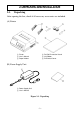
2.UNPACKING AND INSTALLATION 2-1. Unpacking After opening the box, check if all necessary accessories are included. (A) Printer 1 Printer 2 User’s Manual 3 Paper Holders 4 Re-Roll Prevention Guard 5 Ink Ribbon 6 DIP Switch Cover (B) Power Supply Unit 1 1 Power Supply Unit 2 User’s Manual Figure 2-1.
2-2. Installation of Paper Holders and Re-Roll Prevention Guard (Only Model DP8340FC) Install the Paper Holders in the outermost holes in the rear of the printer. Figure 2-2.
Install the Re-Roll Prevention Wire in the holes of the printer cover. Twisting the Wire as shown in the figure below, will make the installation easier. Figure 2-3. Installation of Re-Roll Prevention 2-3. Handling Notes (1) (2) (3) Install the printer near an easily accessible socket-outlet. Place the unit on a flat and stable surface for operation. Do not connect the AC Power Plug to the same outlet used for other noise generating devices (large motors, etc.).
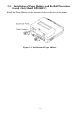
3.PART IDENTIFICATION AND NOMENCLATURE 3-1. Power Supply Unit DC Power Connector (Output) Shape of AC Power plug will vary according to destinations. Figure 3-1.
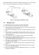
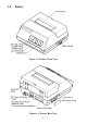
3-2. Printer Figure 3-2. Printer: Front View Figure 3-3.
3-3. Part Functional Description (1) (2) (3) (4) (5) AC Power Plug DC Power Outlet Printer Cover POWER Lamp ON LINE Lamp Connect to an outlet of the specified voltage. Supplies DC 12V power to the printer. Protects the printer against dust and reduces noise. Lights up (green LED) when power is on. Lights up (green LED) when the unit is in the online mode. (6) ALARM Lamp Lights up (red LED) when printer operation is not normal, or the printer is out of paper.
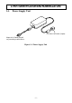
4. INSTALLATION OF INK RIBBON AND PAPER 4-1. Installation of Ink Ribbon (1) Turn power off, lift the Printer Cover up and remove it. Note: Be careful not to touch the print head immediately after printing, because it can get very hot. Figure 4-1. Printer Cover Removal (2) (3) (4) Unwind ribbon so that the spools are separated as shown in Figure 4-3. Hold the ribbon taut as shown with the drive pins facing down and slide the ribbon between the print head and the platen.
Ribbon Life Ribbon life Description Black SF-03B (Fuji Kagakushi Kogyo Co., Ltd.) Approx. 0.8 million characters Figure 4-2. Installation of Ink Ribbon Figure 4-3. Ribbon Spools 4-2. Removal of Ink Ribbon Hold the spool and lift gently, rotating it until the ribbon sags. Push the ribbon detecting lever out, lift the spool until it comes off the shaft. Remove the second spool in a similar manner. (Do not apply excessive force when lifting spools.
4-3. Paper Insertion 4-3-1. Model DP8340FC (1) (2) (3) (4) Cut the Roll Paper end straight and square. Hold the roll so that the paper comes from the bottom. Attach the Roll Paper to the Holders Paper by slipping one side of the roll onto the Hub and pulling the other Hub out to allow the roll to slip in place. Insert the paper evenly into the Paper Insertion Slot. Turn the Power Switch “ON”, and press the FEED Button. The paper will be fed into the unit. Figure 4-4.
4-3-2. Model DP8340SC 1. 2. 3. 4. Make a straight cut along the top of the paper, about 1/4 inch away from the sprocket holes, (as shown in the figure). If there is perforation, cut the paper on the perforation. Insert the paper squarely into the paper insertion slot until the ALARM lamp goes out. Then, hold down the FEED switch to advance the paper 8 lines, and release the switch when 8-line feeding is completed.
4-4. Paper Removal Cut the paper close to the slot and use the feed button until paper has passed completely through the printer. Note: Do not try to remove the paper by hand as it could become crooked and get jammed inside the printer.
5.CONTROL CODES CODE FUNCTION LF (0A)H Print and line feed instruction OUTLINE The LF code causes the data in the line buffer to be printed, followed by a single line feed. When the line buffer is empty, only the feed takes place. CODE CR (0D)H Print and line feed instruction FUNCTION OUTLINE Same function as of LF code. However, when the DIP switch 3 is ON, the CR code becomes invalid.
CODE FUNCTION SI (0F)H Inverted print instruction OUTLINE This function causes the printing to be inverted. This code must be received at the beginning of a line. If this code is received anywhere other than at the beginning of a line, it is disregarded. Accordingly, normal characters and inverted characters, can not be mixed on the same line. CODE DC2 (12)H Release from inverted print instruction FUNCTION OUTLINE The inverted print instruction is released by this code.
CODE FUNCTION ESC R n (1B)H (52)H n Select an international character. OUTLINE This command selects one of the international character sets in accordance with the value of “n” as shown below. n = 0 : U.S.A. 3 : England 6 : Italy 1 : France 4 : Denmark 7 : Spain 2 : Germany 5 : Sweden 8 : Japan International character set can be specified using the DIP Switches. However, control code settings have priority.
Relation Between Character Pattern Data and the Print Head CODE FUNCTION ESC % 1 (1B)H (25)H (01)H or (1B)H (25)H (31)H Select download character OUTLINE This code specifies the download mode. Download characters defined by the previously explained &0 code cannot be printed unless this code is first sent to the printer.
If the position into which the download character is written (the character code) is defined as (21)H, (22)H, (23)H, then we have n1 = (21)H, n2 = (23)H The relation between the character pattern data and the print head assigns the 9 pin as unused. Therefore, m0 = (80)H. If data m1 to m18 is converted to hexadecimal, it appears as follows. Data m1 m2 m3 m4 m5 Binary 10100000 10100000 10111110 10100000 10100000 DATA TRANS MISSION Hex. A0 A0 BE A0 A0 Data m1 m2 m3 m4 m5 Binary Hex.
CODE FUNCTION ESC N n (1B)H (4E)H n Sets bottom margin in lines OUTLINE Upon receiving this code, the bottom margin is set to n lines. 0 n 120; Default Value n = 0 CODE FUNCTION ESC O (1B)H (4F)H Cancels bottom margin. OUTLINE Upon input of this code, bottom margin setting is cleared. CODE FF (0C)H Form feed FUNCTION OUTLINE The FF code prints the data in the current line and transports the paper to the start of the next page.
Executed by BEL code and FS code after printing. CODE FUNCTION BEL (07)H Trigger peripheral unit drive (Deferred) OUTLINE Causes a peripheral drive pulse to be generated. This code is normally stored in the buffer and is performed as it is received from the data queue. CODE FUNCTION FS (1C)H Trigger peripheral unit drive (immediate) OUTLINE Causes a peripheral drive pulse to be generated immediately.
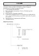
Character Code List Character Code 1 LF 2 CR (0A)H (0D)H 3 SO 4 DC4 5 ESC-1 (0E)H (14)H (1B)H (2D)H(01)H (1B)H (2D)H (31)H (1B)H (2D)H(00)H (1B)H (2D)H (30)H (0F)H (12)H (1B)H (45)H 6 ESC-0 7 SI 8 DC2 9 ESC E 10 11 12 13 14 15 ESC F ESC 4 ESC 5 ESC R n ESC & 0 ... ESC % 1 17 ESC a n 18 ESC C n (1B)H (46)H (1B)H (34)H (1B)H (35)H (1B)H (52)H n (1B)H (26)H (00)H ...
Character Code 23 ESC BEL n1 n2 (1B)H (07)H n1 n2 24 BEL 25 FS (07)H (1C)H 26 SUB 27 CAN (1A)H (18)H Function Set peripheral unit drive pulse duration 1 n1 127, 1 n2 127 (default n1 = n2 = 20) Trigger peripheral unit drive 1 (Deferred) Trigger peripheral unit drive (Immediate) Trigger peripheral unit drive 2 (immediate) Clears print buffer – 21 –
6.GENERAL SPECIFICATIONS Printing method Serial impact dot matrix printing, 9 wires Number of print columns 40 columns, 12 CPI Print speed Approx. 2 lines/sec Print direction Bi-directional Line spacing 1/6 inch Paper feed method Friction Feed or Sprocket-feed Paper feed speed Approx.
Paper specification Paper type Size Paper width Roll diameter Thickness (single) (2 copy) Paper end Ink ribbon specification Color Ribbon material Ribbon size Spool Recommended ribbon Operating conditions Storage conditions Head life Printer reliability Ordinary and carbonless copy paper 114.3 mm (4.5 inches) 80 mm outer diameter (Max) 0.07 mm (52.3 g/m2) to 0.09 mm (64g/m2) One copy and one original (max 0.
Figure 6-1. Roll Paper and Print Area [Model DP8340FC] Figure 6-2.
60mm Figure 6-3. External Dimensions (Printer) 36mm 120mm 2.0m Shape of AC Power plug will vary according to destinations. Figure 6-4.
7. INTERFACE 7-1. Interface Specifications This printer has a parallel interface to communicate with the computer. The operating specifications of the parallel interface are as follows. (1) Data transfer rate 1000 to 6000 characters per second (2) Synchronization Via externally supplied STROBE pulses (3) Handshaking ACK and BUZY signals (4) Logic level Compatible with TTL level 7-2. Interface Timing Figure 7-1.
7-3. Connectors and Signals Pin No.Signal Name IN/OUT 1 STROBE IN 2-9 DATA1-8 IN 10 ACK OUT 11 BUSY OUT PAPER OUT 13 SELECTED 14-15 N/C SIGNAL 16 GND CHASSIS 17 GND 18 N/C 19-30 GND 12 OUT OUT Signals when data is ready to be read.Signal gose from HIGH to LOW (for at least 0.5 microsec.) when data is available. These signals provide the information of the first to eighth bits of parallel data.Each signal is at HIGH level for a logical 1 and at a LOW level for a logical 0.
7-4. Switch 1 2 3 4 (*1) 5 (*2) 6 7 8 Setting of the DIP Switches Factory settings : all ON ON OFF Function Character Table (See below) Control cord CR Printing Direction (Red printing) Ink Ribbon Disable Bi. 2-color Enable Uni. monochrome International Character Set (See below) (*1) DIP Swich 4 should be set to OFF when you use 2-part sprocket paper having the seam on the right since the ribbon snags at the seam if shifted. The DIP Switch 4 Should be otherwise set to ON.
7-5. Peripheral Unit Drive Circuit The Control Board of this printer is equipped with a circuit for driving peripheral units (Paper Cutter, Take-Up Device, Cash Drawer, etc.) The 6P Modular Jack is used as the Drive Circuit. When using this circuit, connect the peripheral unit cable to the 6P Modular Jack (cable is not included). Note: Peripheral unit drive circuit connector only connects to peripheral units such as cash drawers, etc. Do not connect it to a telephone. 1.
8. CHARACTER CODE LIST 1) U.S.A.
– 31 –
2) IBM Character Set #1 (DIP SW1: OFF, SW2: ON) – 32 –
– 33 –
3) IBM Character Set #2 (DIP SW1: ON, SW2: OFF) – 34 –
– 35 –
4) JAPAN (DIP SW1: OFF, SW2: OFF) – 36 –
– 37 –
International Character Sets – 38 –
9. FONT LIST 1) U.S.A.
– 40 –
– 41 –
2) IBM Character Set #1 (DIP SW1: OFF, SW2: ON) – 42 –
– 43 –
– 44 –
3) IBM Character Set #2 (DIP SW1: ON, SW2: OFF) – 45 –
– 46 –
– 47 –
4) JAPAN (DIP SW1: OFF, SW2: OFF) – 48 –
– 49 –
– 50 –
International Character Sets – 51 –
10. WHEN POWER IS SUPPLIED BY THE USER When printer power is supplied by the user rather than through the accessory power source unit, please be careful of the following points. Note 1: The power supply must be +12V +10% –5% 2A or above. An electrolytic capacitor (C = 4700µF/25V to 6800µF/25V) must be connected across the output of the power supply. Note 2: A DC power plug is available as an option. GND +12V GND Reference: Design the power supply referring to the power supply circuit shown below.
VAC 14V C2 100 ~ 200µF/25V VDC 12V +10% –5% ZD1 VZD = 14V (1W) IAC C1 2 ~ 3A 6800µF/25V C3 TR1 4700 ~ 6800µF/25V 2SD633 (TOSHIBA) Other parameters may be determined by user. Figure 10-1.
- MEMO -
ELECTRONIC PRODUCTS DIVISION STAR MICRONICS CO., LTD. OVERSEAS SUBSIDIARY COMPANIES STAR MICRONICS AMERICA, INC. 536 Nanatsushinnya, Shimizu, Shizuoka 424-0066 Japan Tel: 0543-47-0112, Fax: 0543-48-5271 70-D Ethel Road West, Piscataway, NJ 08854 U.S.A Tel: 732-572-9512, Fax: 732-572-5095 STAR MICRONICS U.K. LTD. Please access the following URL http://www.star-micronics.co.jp/service/sp_sup_e.htm for the lastest revision of the manual.