DOT MATRIX PRINTER DP8340 SERIES [SERIAL INTERFACE] USERS MANUAL
Federal Communications Commission Radio Frequency Interference Statement This equipment has been tested and found to comply with the limits for a Class A digital device, pursuant to Part 15 of the FCC Rules. These limits are designed to provide reasonable protection against harmful interference when the equipment is operated in a commercial environment.
TABLE OF CONTENTS 1. OUTLINE .............................................................................................. 1 2. UNPACKING AND INSTALLATION ................................................ 2 2-1. Unpacking .................................................................................... 2 2-2. Installation of Paper Holders and Re-Roll Prevention Guard (Only Model DP8340F) ............................................................... 3 2-3. Handling Notes.................................
8. INTERFACE FOR MODEL DP8340-D (D-SUB 25 PIN CONNECTOR) ......................................................... 28 8-1. Interface Specifications .............................................................. 28 8-2. Interface Circuit ......................................................................... 29 8-2-1. RS-232C .......................................................................... 29 8-2-2. Current Loop ................................................................... 29 8-3.
1. OUTLINE The DP8340 series of serial dot matrix printers is for use in ECR, POS, electronic instruments, banking machines and computer peripheral equipment. The DP8340 series include the following features; 1) 2 color printing (Red and Black) 2) High-speed bidirectional printing (2 line/sec, 40 columns per line) 3) 9-pin print head 4) The interface conforms to RS-232C in M type, and to RS-232C/20mA Current Loop in D type.
2.UNPACKING AND INSTALLATION 2-1. Unpacking After opening the box, check if all necessary accessories are included. (A) Printer 1 2 3 4 5 Ink Ribbon 6 DIP Switch Cover 7 Ferrite Core (EU only) Printer User’s Manual Paper Holders Re-Roll Prevention Guard (B) Power Supply Unit 1 1 Power Supply Unit 2 User’s Manual Figure 2-1.
2-2. Installation of Paper Holders and Re-Roll Prevention Guard (Only Model DP8340F) Install the Paper Holders in the outermost holes in the rear of the printer. Figure 2-2.
Install the Re-Roll Prevention Wire in the holes of the printer cover. Twisting the Wire as shown in the figure below, will make the installation easier. Figure 2-3. Installation of Re-Roll Prevention 2-3. Handling Notes (1) (2) (3) Install the printer near an easily accessible socket-outlet. Place the unit on a flat and stable surface for operation. Do not connect the AC Power Plug to the same outlet used for other noise generating devices (large motors, etc.).
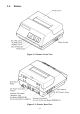
3.PART IDENTIFICATION AND NOMENCLATURE 3-1. Power Supply Unit DC Power Connector (Output) Shape of AC Power plug will vary according to destinations. Figure 3-1.
3-2. Printer Figure 3-2. Printer: Front View Figure 3-3.
3-3. Part Functional Description (1) (2) (3) (4) (5) AC Power Plug DC Power Outlet Printer Cover POWER Lamp ON LINE Lamp Connect to an outlet of the specified voltage. Supplies DC 12V power to the printer. Protects the printer against dust and reduces noise. Lights up (green LED) when power is on. Lights up (green LED) when the unit is in the online mode. (6) ALARM Lamp Lights up (red LED) when printer operation is not normal, or the printer is out of paper.
4. INSTALLATION OF INK RIBBON AND PAPER 4-1. Installation of Ink Ribbon (1) Turn power off, lift the Printer Cover up and remove it. Note: Be careful not to touch the print head immediately after printing, because it can get very hot. Figure 4-1. Printer Cover Removal (2) (3) (4) Unwind ribbon so that the spools are separated as shown in Figure 4-3. Hold the ribbon taut as shown with the drive pins facing down and slide the ribbon between the print head and the platen.
Figure 4-2. Installation of Ink Ribbon Figure 4-3. Ribbon Spools 4-2. Removal of Ink Ribbon Hold the spool and lift gently, rotating it until the ribbon sags. Push the ribbon detecting lever out, lift the spool until it comes off the shaft. Remove the second spool in a similar manner. (Do not apply excessive force when lifting spools.
4-3. Paper Insertion 4-3-1. Model DP8340F (1) (2) (3) (4) Cut the Roll Paper end straight and square. Hold the roll so that the paper comes from the bottom. Attach the Roll Paper to the Holders Paper by slipping one side of the roll onto the Hub and pulling the other Hub out to allow the roll to slip in place. Insert the paper evenly into the Paper Insertion Slot. Turn the Power Switch “ON”, and press the FEED Button. The paper will be fed into the unit. Figure 4-4.
4-3-2. Model DP8340S 1. 2. 3. 4. Make a straight cut along the top of the paper, about 1/4 inch away from the sprocket holes, (as shown in the figure). If there is perforation, cut the paper on the perforation. Insert the paper squarely into the paper insertion slot until the ALARM lamp goes out. Then, hold down the FEED switch to advance the paper 8 lines, and release the switch when 8-line feeding is completed.
4-4. Paper Removal Cut the paper close to the slot and use the feed button until paper has passed completely through the printer. Note: Do not try to remove the paper by hand as it could become crooked and get jammed inside the printer.
5.CONTROL CODES CODE FUNCTION LF (0A)H Print and line feed instruction OUTLINE The LF code causes the data in the line buffer to be printed, followed by a single line feed. When the line buffer is empty, only the feed takes place. CODE CR (0D)H Print and line feed instruction FUNCTION OUTLINE Same function as of LF code. However, when the DIP switch 2-4 is ON, the CR code becomes invalid.
CODE FUNCTION SI (0F)H Inverted print instruction OUTLINE This function causes the printing to be inverted. This code must be received at the beginning of a line. If this code is received anywhere other than at the beginning of a line, it is disregarded. Accordingly, normal characters and inverted characters, can not be mixed on the same line. CODE DC2 (12)H Release from inverted print instruction FUNCTION OUTLINE The inverted print instruction is released by this code.
CODE FUNCTION ESC a n (1B)H (61)H n n-line feed OUTLINE After printing the data in the current line, n lines are fed by this code. The value of n ranges from 1 to 120. CODE ESC C n (1B)H (43)H n Sets page length in lines FUNCTION OUTLINE This code sets the length of a page to n lines. The value of n ranges from 1 to 120. On initialization, the page length default condition will be 42 lines. The line feed pitch is onesixth inch.
CODE FUNCTION ESC @ (1B)H (40)H Printer initialization OUTLINE All printing conditions except ESC BEL n1 n2, the line buffer and data buffer are set to the power on default condition. CODE ESC BEL n1 n2 (1B)H (07)H n1 n2 Sets peripheral unit drive pulse duration. FUNCTION OUTLINE This command sets the pulse duration for peripheral unit drive (Paper Cutter, Take-Up Device, cash drawer, etc.
FUNCTION FS (1C)H Trigger peripheral unit drive (immediate) OUTLINE Causes a peripheral drive pulse to be generated immediately CODE ENQ (05)H Enquiry CODE FUNCTION OUTLINE When this code is received, the printer outputs status data. If it is input after text data input in the STX-ETX mode, the printer outputs status data and the check byte. CODE STX (02)H Start of text FUNCTION OUTLINE When this code is received, the printer enters the STX-ETX mode.
Character Code List Character Code 1 LF 2 CR (0A)H (0D)H 3 SO 4 DC4 5 ESC-1 7 SI 8 DC2 9 ESC E (0E)H (14)H (1B)H (2D)H(01)H (1B)H (2D)H (31)H (1B)H (2D)H(00)H (1B)H (2D)H (30)H (0F)H (12)H (1B)H (45)H 10 11 12 13 14 ESC F ESC 4 ESC 5 ESC a n ESC C n (1B)H (46)H (1B)H (34)H (1B)H (35)H (1B)H (61)H n (1B)H (43)H n 15 ESC N n (1B)H (4E)H n 16 17 18 19 (1B)H (4F)H (0C)H (1B)H (40)H (1B)H (07)H n1 n2 6 ESC-0 ESC O FF ESC @ ESC BEL n1 n2 20 BEL 21 FS (07)H (1C)H 22 23 24 25 (05)H (02)H (03)H (1
6.GENERAL SPECIFICATIONS Printing method Serial impact dot matrix printing, 9 wires Number of print columns 40 columns, 12 CPI Print speed Approx. 2 lines/sec Print direction Bi-directional Line spacing 1/6 inch Paper feed method Friction Feed or Sprocket-feed Paper feed speed Approx.
Ink ribbon specification Color Ribbon material Ribbon size Spool Recommended ribbon Operating conditions Storage conditions Head life Printer reliability Black and red Nylon (#40 denier) 13mm × 6m 13mm (width), 35mm in diameter (two spool) SF-03BR (manufactured by Fuji Kagakushi Kogyo Co., Ltd.) or approved equivalent. Temperature +5˚C — +40˚C Humidity 10% — 80%RH Temperature –20˚C — +70˚C Humidity 5% — 95%RH (+40˚C) 70 million characters 5.0 million lines MCBF (except head life) Figure 6-1.
60mm Figure 6-3. External Dimensions (Printer) 36mm 120mm 2.0m Shape of AC Power plug will vary according to destinations. Figure 6-4.
7. INTERFACE FOR MODEL DP8340-M (MODULAR JACK CONNECTOR) 7-1.
7-3. Setting of the DIP Switches 7-3-1.
7-4. Connectors and Signals Direction 1 2 Signal Name GND GND 3 TXD OUT 4 5 RXD RTS IN OUT 6 FAULT OUT 7 GND — 8 DTR OUT Pin No. — — Function Shield Ground Frame Ground This pin carries data from the printer. (Return channel) This pin carries data to the printer. This is SPACE when the printer power is ON. This is MARK when the printer is abnormal. (Machine Error.) Or there is a paper error. Signal ground. This printer turns this pin SPACE when it is ready to receive data. Figure 7-3.
7-5. Interface Connections For interface connections, refer to the instructions for interface of the host computer. The following gives basic examples. M TYPE ONLY Figure 7-4. Interface Connections using Modular/D-Sub 25 Adapter to IBM PC (Use with straight through cable wiring) Before selecting interface cable wiring, it is necessary to know the wiring of the modular interconnect cable. Figure 7-5. below shows the way to determine if the cable is straight connected, or cross connected.
Figure 7-6. Wiring of cable for direct connection between DP8340 and IBM PC serial part 7-6. Peripheral Unit Drive Circuit The Control Board of this unit is equipped with a circuit for driving a peripheral unit (Paper Cutter, Take-Up Device, Cash Drawer, etc.) The Control Board Connector (CN3) is used to connect the Peripheral Unit to the Drive Circuit. When using this circuit connect the peripheral unit cable to the CN3 Connector (cable is not included).
M TYPE ONLY Figure 7-8. Cable Connection 7-6-2. Peripheral Drive Circuit D1 Absolute Ratings (Ta = 25˚C) Voltage Breakdown 100V Peak Forward Current 1A Drive Output 12V, MAX. 1A Figure 7-9. Drive Circuit Caution: Do not use external power supply with peripheral drive circuit. 7-6-3. Control Codes Codes for Drive Circuit control are ESC BEL n1 n2, BEL and FS. Refer to the Control Codes in Chapter 5.
8. INTERFACE FOR MODEL DP8340-D ( D-SUB 25 PIN CONNECTOR ) 8-1.
8-2. Interface Circuit 8-2-1. RS-232C Input (RXD, CTS) D TYPE ONLY Output (DTR, FAULT, TXD, RCH, RTS) Figure 8-1. RS232-C Interface 8-2-2. Current Loop Input (TTY-RXD, TTY-RXDR) Output (TTY-TXD, TTY-TXDR) Note: Resistance should be set so that Current Loop is restricted to the range of 10 ~ 20 mA. Figure 8-2.
8-3. Setting of the DIP Switches 8-3-1.
8-4. Jumper Setting The serial interface is set to the RS-232C mode upon shipment from the factory. When using in the 20mA current loop mode, it is necessary to set the jumpers. The jumpers built into the Control Board allow for setting of functions shown in the table. However, the Bottom Cover must be removed to perform this setting. For setting the Jumper, disconnect the power source beforehand. D 8-4-1. Removal of the Bottom Cover TYPE ONLY Figure 8-4. Removal of the Bottom Cover 8-4-2.
8-5. Connectors and Signals Pin No. Signal Name Direction 1 GND — 2 TXD OUT 3 RXD IN 4 RTS OUT 5 CTS IN 6 DSR IN 7 8 GND N/C — 9 TTY TXDR — 10 TTY TXD OUT 11 RCH OUT 12 13 N/C GND — 14 FAULT OUT 15 ~ 16 N/C 17 TTY TXDR — 18 TTY RXDR — 19 TTY RXD IN 20 DTR OUT 21 ~ 22 N/C 23 TTY RXDR — 24 TTY TXD OUT 25 TTY RXD IN Function Frame Ground This pin carries data from the printer. (Return channel) This pin carries data to the printer.
Figure 8-5. D-Sub 25 Pin Connector 8-6. Interface Connections D For interface connections, refer to the instructions for interface of the host TYPE computer. The following gives one basic example of connections. ONLY Figure 8-6.
8-7. Peripheral Unit Drive Circuit The Control Board of this unit is equipped with a circuit for driving a peripheral unit (Paper Cutter, Take-Up Device, Cash Drawer, etc.) The Control Board Connector (CN3) is used to connect the Peripheral Unit to the Drive Circuit. When using this circuit connect the peripheral unit cable to the CN3 Connector (cable is not included). Use a cable with the following specifications: Note: Do not run cable near devices generating large amounts of electrical noise.
D TYPE ONLY Figure 8-8. Cable Connection 8-7-2. Peripheral Drive Circuit D1 Absolute Ratings (Ta = 25˚C) Voltage Breakdown 100V Peak Forward Current 1A Drive Output 12V, MAX. 1A Figure 8-9. Drive Circuit Caution: Do not use external power supply with peripheral drive circuit. 8-7-3. Control Codes Codes for Drive Circuit control are ESC BEL n1 n2, BEL and FS. Refer to the Control Codes in Chapter 5.
9. DATA STRUCTURE AND CONTROL 9-1. DTR Mode (1 BLOCK) Controls Data Transfer by using DTR line as BUSY FLAG (a) (b) In case of Paper Empty Paper Empty When the paper out detector indicates end of paper, the printer stops printing after a maximum of two lines of printing or paper feed. The printer goes OFF LINE and sets the DTR to “MARK” status immediately after occurrence of a paper empty.
9-2. X-ON/X-OFF Mode The printer transmits an X-ON (Control Code; DC1, Hexadecimal Value; 11H,) signal after power is turned on, if there is no printer error being generated. When this signal is received by the host computer, the host computer transmits the data to the printer. The X-ON signal is output intermittently every three seconds until the host computer receives and responds to this signal.
Paper Empty When the paper out detector indicates end of paper, the printer stops printing after a maximum of two lines of printing or paper feed. The host computer can receive the printer status by transmitting an ENQ code to the printer. The printer goes OFF LINE and sets the DTR to “MARK” status in 5 seconds after occurrence of a paper empty. It is necessary to install paper into the printer and press the ON LINE BUTTON to light the ON LINE LAMP in order to recover from paper empty status.
9-3. STX-ETX Mode The start of the STX-ETX mode should occur with a totally empty print buffer. This can be achieved by sending an ENQ code to the printer and checking the status until the status code indicates an empty buffer. At that point, the STX code is sent by the host computer followed by a data block. While receiving the data block, the printer generates a horizontal parity check character.
STX-ETX Mode Flow Diagram – 40 –
10.
– 42 –
International Character Sets – 43 –
11.
– 45 –
– 46 –
International Characters – 47 –
12. WHEN POWER IS SUPPLIED BY THE USER When printer power is supplied by the user rather than through the accessory power source unit, please be careful of the following points. Note 1: The power supply must be +12V +10% –5% 2A or above. An electrolytic capacitor (C = 4700µF/25V to 6800µF/25V) must be connected across the output of the power supply. Note 2: A DC power plug is available as an option. GND +12V GND Reference: Design the power supply referring to the power supply circuit shown below.
VAC 14V C2 100 ~ 200µF/25V VDC 12V +10% –5% ZD1 VZD = 14V (1W) IAC C1 2 ~ 3A 6800µF/25V C3 TR1 4700 ~ 6800µF/25V 2SD633 (TOSHIBA) Other parameters may be determined by user. Figure 12-1.
13. FERRITE CORE INSTALLATION ( EU ONLY ) If a peripheral unit drive circuit is to be used, attach a ferrite core using the following instructions. ■ A ferrite core noise filter for the peripheral unit cable comes packed with the printer for distribution throughout the European Union. Ferrite cores must be purchased separately in other areas. • Cable is not included. • Use a cable with the following specifications.
■ Clamp the ferrite core onto the peripheral unit cable, looping the cable as shown in Figure 13-2. • Take care to avoid damaging the cable when installing the ferrite core. • The ferrite core should be anchored firmly in place with the fastener that comes with it, as shown in Figures 13-3. and 13-4. • Do not forget to loop the cable. ■ Cable connection Remove the printer Bottom Cover and connect the cable to the CN3 Connector.
ELECTRONIC PRODUCTS DIVISION STAR MICRONICS CO., LTD. OVERSEAS SUBSIDIARY COMPANIES STAR MICRONICS AMERICA, INC. 536 Nanatsushinnya, Shimizu, Shizuoka 424-0066 Japan Tel: 0543-47-0112, Fax: 0543-48-5271 70-D Ethel Road West, Piscataway, NJ 08854 U.S.A Tel: 732-572-9512, Fax: 732-572-5095 STAR MICRONICS U.K. LTD. Please access the following URL http://www.star-micronics.co.jp/service/sp_sup_e.htm for the lastest revision of the manual.