USER’S MANUAL LC-1011C LC-100 + COLOUR DOT MATRIX PRINTER HL 80825190
Federal Communications Commission Radio Frequency Interference Statement The 120V version equipment has been tested and found to comply with the limits for a Class B digital device, pursuant to Part 15 of FCC Rules. These limits are designed to provide reasonable protection against harmful interference in a residential installation.
Trademark acknowledgments LC-10, LC-100, LC-100+, LC-200, LC-1011C, NX-1000, NX-1020, NX-1040, PT-10DT, SPC-8K: Star Micronics Co. Ltd. EX-800, FX-850, LX-810, LX-850: Seiko Epson Corporation IBM PC, IBM Proprinter, IBM Proprinter2, IBM Proprinter 3: International Business Machines Corporation. TrueType: Apple Computer Inc. MS-DOS, Microsoft windows: Microsoft Corporation Notice • All rights reserved.
About this manual This manual describes how to set up, use, and care for the Star LC-1011C and LC-100+ Colour printers. The following is a list of what you can expect to find in each chapter.
Contents Chapter 1: Printer Setup ... 1 Choosing a place for the printer ... 1 Unpacking the printer ... 2 General guide ... 3 Installing the platen knob ... 4 Opening the front cover ... 4 Installing the ribbon cassette ... 5 Removing the ribbon cassette ... 7 Installing the paper guide ... 8 Connecting to a power outlet and turning power on and off ... 8 Loading fanfold paper ... 9 Printing on fanfold paper ... 12 Parking fanfold paper ... 13 Unparking fanfold paper ... 13 Using the tear-off function ...
Chapter 3: Using the EDS Mode ... 24 About EDS Mode settings ... 24 Entering the EDS Mode ... 24 Selecting a bank ... 25 Selecting a switch ... 25 Changing a switch setting ... 25 Printing the current switch settings ... 26 Exiting the EDS Mode ... 26 EDS Mode Settings ... 26 Chapter 4: Using the Printer with MS-DOS ... 33 Setting up for printing with MS-DOS ... 33 Chapter 5: Paper Handling ... 35 Selecting paper types ... 35 Cut-Sheet Paper (Manual Feed) ...
Appendix E: Printer Control Codes ... 67 Appendix F: Glossary ... 72 Appendix G: Control Panel Operation Guide ...
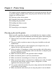
1 Chapter 1: Printer Setup This chapter contains important information on setting up your printer. Be sure to read this chapter carefully before using the printer for the first time.
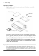
2 Printer Setup Unpacking the printer Check to make sure that the carton contains each of the items shown in the following illustration. Ribbon cassette 3.5” Floppy disk If anything is missing, contact the store where you bought the printer and ask them to supply the missing part. Note that it is a good idea to keep the original box and all the packing materials just in case you need to pack the printer up again and send it somewhere at a later date.
General guide General guide The following illustrations show the major components of your printer.
4 Printer Setup Installing the platen knob The platen knob is packed into a recess in the packaging material. ❏ Install the knob on the shaft located inside the large hole on the right side of the printer. Make sure that the two splines of the platen shaft inside the printer fit into the slots inside the knob’s spindle. Press the knob carefully but firmly into place as far as it will go. Opening the front cover ❏ Lift up on the front cover while pressing in gently on its sides.
Installing the ribbon cassette 5 Note: You can completely remove the front cover from the printer or you can stand it up without removing it. You should normally leave the front cover closed, because it protects against objects getting into the printer, and it cuts down on printer noise. Installing the ribbon cassette ❏ Make sure that the printer is unplugged from its power outlet. Caution! Never move the print head while the printer is turned on. Doing so can damage the printer.
6 Printer Setup ❏ While guiding the ribbon between the print head and print head shield, press down gently but firmly on the cassette until the side tabs snap securely into place. Print head shield Print head Ribbon cassette ❏ Rotate the knob on the cassette again to take up any slack. ❏ Close the front cover of the printer. Note: If you want to print with color, use an optional LC9CL color ribbon cassette.
Removing the ribbon cassette 7 ✓ Are you getting muddy-looking colors from a color ribbon? The more ✓ green, orange, and purple colors you use, the quicker the primary colors (blue, red, yellow) will become mixed with other colors. This will cause a drop in performance of the ribbon. Remember that changing the ribbon before it becomes frayed or completely out of ink extends the life of your print head.
8 Printer Setup Installing the paper guide ❏ Insert the two tabs on the bottom of the paper guide into the holes provided on the rear cover of the printer. ❏ To remove the paper guide from the printer, simply pull the tabs out of the holes. Note: Lay the paper guide down flat when using fanfold paper, and stand it up when using cut-sheet paper.
Loading fanfold paper 9 Note: We recommend that you unplug the printer from the power outlet whenever you do not plan to use it for long periods. Because of the this, you should locate the printer so that the power outlet it is plugged into is nearby and easy to access. At this point you may want to perform a test of the printer to make sure it is working properly. See “Testing the printer” on page 47 for details on how to perform tests.
10 Printer Setup ❏ Grasping the two back corners of the printer with the palms of your hands, press back on the two raised areas on the top of the rear cover until it opens. ❏ Swing the rear cover back and down until it stops. Note: You can also completely remove the rear cover by simply pulling it away from the back of the printer after you open it. ❏ Pass the fanfold paper through the space between the printer case and the ❏ ❏ rear cover.
Loading fanfold paper 11 far apart). After making these adjustments, be sure that you re-lock the tractors by pulling the gray levers into the locked position. ❏ Close the rear cover and press down gently on it until it locks into place with a click. Note: If you removed the rear cover, first insert its two tabs into the holes provided in the back of the printer and then swing it closed. ❏ Install the paper guide so that it lays down flat as shown below.
12 Printer Setup ❏ Pull the bail lever toward the front of the printer. This will feed the paper to the starting position. LOAD ❏ After the paper is fully fed (indicated by the printer’s beeping), return the bail lever back to its original position toward the back of the printer. Important! Never return the bail lever to its original position until the paper is fully fed. The printer will beep when you can return the bail lever to its original position.
Parking fanfold paper 13 Parking fanfold paper It is not necessary to remove fanfold paper currently loaded in the printer in order to print on cut-sheet paper. Instead, simply use the following procedure to park the fanfold paper. ❏ Tear off the paper at a perforation so there is no more than half a page ❏ ❏ ❏ ❏ sticking out of the front cover of the printer. If necessary, you can press the control panel’s ON LINE button to put the printer off-line.
14 Printer Setup Using the tear-off function The following procedure makes it easy to tear off fanfold paper. ❏ Check to make sure that the printer is on-line. ❏ Press the FONT button to perform the long tear-off operation, or press the ❏ PITCH button to perform the short tear-off operation. The long tear-off operation causes the paper to be fed automatically so the tear assist edge of the printer cover is aligned with the paper’s next perforation.
Connecting to your computer 15 For an IBM-compatible personal computer: ✓ Use a standard 36-pin Centronics parallel cable. ✓ The parallel cable should be no longer than six feet (two meters). Longer cables can result in poor transfer of information. Important! Make sure that the printer and the computer are turned off before connecting them. ❏ Plug one end of the parallel cable into the parallel port of your computer.
16 Chapter 2: Control Panel Operations The control panel gives you push-button control over the printer’s operations. It includes indicator lights, which tell you the current status of the printer at a glance. DRAFT 10CPI POWER MICRO FEED COURIER 12CPI QUIET SANSERIF FONT QUIET PROP PITCH PAPER FEED MACRO PARK COND ALT ON LINE FF CLEAR This chapter describes control panel functions that can be performed while the printer is turned on and either on-line or off-line.
Selecting a font 17 Selecting a font ❏ Make sure the printer is off-line (ON LINE indicator is not lit). ❏ Press FONT to change the font selection. An indicator lights to the left of the name of the font that is currently selected. The following shows the fonts that are available. Lit Indicator Font Name DRAFT Draft COURIER Courier SANSERIF Sanserif Note: The font setting you make with the above procedure can be changed if the software you are using overrides the setting from the control panel.
18 Control Panel Operations Setting the character pitch The character pitch setting controls how many characters are printed per inch. Use the following procedure to select the pitch you want. ❏ Make sure the printer is off-line (ON LINE indicator is not lit). ❏ Press PITCH to change the pitch selection. The following shows the meanings of the indicators that light on the control panel when you press PITCH.
Line feed 19 The printer is now in the Pitch Lock Mode. You could enter the Pitch Lock Mode and Font Lock Mode (page 17) at the same time by holding down both FONT and PITCH when you turn on printer power. To exit the Pitch Lock Mode, simply turn the printer off. Important! Font and pitch lock will not function if you are using Windows Truetype fonts. Line feed ❏ Make sure the printer is off-line (ON LINE indicator is not lit). ❏ Press PAPER FEED once to feed paper one line.
20 Control Panel Operations Micro feed Use the following operation to feed the paper in very small increments. This makes it possible to align the print head exactly where you want it. ❏ Make sure the printer is off-line (ON LINE indicator is not lit). ❏ While holding down ON LINE, press PAPER FEED to feed the paper forward or PITCH to feed the paper backward.
Selecting the Quiet Print Mode 21 Selecting the Quiet Print Mode The Quiet Print Mode lets you print with less noise than that produced with normal printing. Use the following procedure to enter and exit the Quiet Print Mode. Important! Though the Quiet Print Mode prints more quietly, it also causes printing to take considerably longer than normal printing. ❏ Make sure the printer is on-line (ON LINE indicator is lit). ❏ Press PAPER FEED, to toggle between the Quiet Print Mode and normal printing.
22 Control Panel Operations ❏ After you have the paper at the position you want, hold down ON LINE ❏ and press PAPER FEED to make the current print head position the new auto load position. The printer will beep twice to indicate that the new auto load position is set. To clear the new auto load position and return to the one that you set previously (using the above procedure), press ON LINE.
Clearing the printer’s buffer 23 Clearing the printer’s buffer When the printer receives data from a computer, it temporarily stores it in a memory called a buffer. If you stop a printing job partway through, there is the chance that some data will remain in the buffer. The following procedure clears the printer’s buffer by deleting any data that might be there. ❏ Execute the necessary command in the program you are using to stop the print job.
24 Chapter 3: Using the EDS Mode The letters “EDS” stand for “Electronic DIP Switches.” Just like the small DIP switches that are used by many computers, printers, and other devices, the EDS lets you configure the printer so that it matches your system and software needs. This chapter describes how to enter the printer’s EDS Mode and provides details about available settings and how to change them. All switch settings, except for D6, are ON when the printer is shipped from the factory.
Selecting a bank 25 Selecting a bank ❏ While in the EDS Mode, use the control panel’s FONT button to select a bank. When the DRAFT indicator flashes, the font and pitch indicators show which bank is currently selected. Lit Indicator Selected Bank COURIER A SANSERIF B QUIET C 12CPI D PROP E COND F Selecting a switch ❏ While in the EDS Mode, use the control panel’s PITCH button to select a bank switch.
26 Using the EDS Mode Printing the current switch settings ❏ To print the current EDS switch settings while in n the EDS Mode, press and hold the control panel’s ON LINE button and then press the PAPER FEED button. Asterisks on the printout show whether a switch is turned on or off. Exiting the EDS Mode ❏ To save EDS settings you have made and exit the EDS Mode, press the ON LINE button. EDS Mode Settings The following details all of the settings you can program in the EDS Mode.
EDS Mode Settings 27 Switch 3: RAM Usage Specifies whether RAM should be used as an input buffer (ON) or as a download buffer (OFF). Selecting input buffer (ON) tells the printer to use available RAM to store data it receives from the computer, which speeds up the printing. Selecting download buffer (OFF) tells the printer to use available RAM to store character patterns.
28 Using the EDS Mode BANK B Switch 1: NLQ Direction Selects uni-directional (ON) or bi-directional (OFF) printing for NLQ (Near Letter Quality) printing. Bi-directional printing (OFF) is faster, while unidirectional (ON) printing generally provides better print quality. Switch 2: Auto Tear-off (Long) Specifies whether the printer’s auto tear-off (long) feature (page 20) is enabled (OFF) or disabled (ON). Note that this setting controls the application software’s tear-off function only.
EDS Mode Settings 29 BANK C Switch 1: Print Mode Selects Draft (ON) or NLQ (OFF) as the print mode. NLQ (OFF) provides near letter quality output, while Draft (ON) provides draft quality. Draft quality printing may be less attractive than near letter quality, but the printing operation is faster. Switch 2: Printable Area Selects Type-A (OFF) or Type-B (ON) as the printable area. Type-A (OFF) causes the print area to start 1/6-inch from the top of the paper and end 1/4-inch from the bottom of the paper.
30 Using the EDS Mode BANK D Switches 1, 2, 3, 4: Page Length Turn these switches on or off to form the pattern that matches the Page Length setting you want to use. Page Length SW1 SW2 SW3 SW4 11”/Letter ON ON ON ON 8” OFF ON ON ON 11.7”/A4 ON OFF ON ON 12” OFF OFF ON ON 8.5”/Letter ON ON OFF ON 14”/Legal OFF ON OFF ON 10.5”/Executive ON OFF OFF ON 7.25”/Executive OFF OFF OFF ON 3.5” ON ON ON OFF 5.
EDS Mode Settings 31 BANK E Switches 1, 2, 3, 4, 5: Code Page/International Character Set If your EDS settings specify IBM emulation (Bank A, Switch 1 OFF) with either character table (Bank A, Switch 2), or Standard emulation (Bank A, Switch 1 ON) with the graphics character table (Bank A, Switch 2 ON), use the Bank E switches to select the default character code page you want to use.
32 Using the EDS Mode If your EDS settings specify Standard emulation (Bank A, Switch 1 ON) with the italic character table (Bank A, Switch 2 OFF), use the Bank E switches to select the international character set you want to use. This setting determines the assignment of 14 character codes in the Standard Italic character set. International Character Set SW1 SW2 SW3 SW4 SW5 U.S.A.
33 Chapter 4: Using the Printer with MS-DOS This chapter contains information about how to use the printer with applications software running under MS-DOS. In this chapter, you will learn about: ❏ How to set up for printing with MS-DOS Setting up for printing with MS-DOS To print from an application running under MS-DOS, you must first select the printer from within the application. Typically, the program will feature an INSTALL or SETUP command for selection of printers.
34 Using the Printer with MS-DOS If none of the printers listed above are available in the application, choose one of the printers listed below. Once again, you should choose the printer that is nearest to the top in the following list. For these printers, you should use the EDS Mode or User Setup Utility to select IBM emulation (page 26). IBM Proprinter III* IBM Proprinter II* IBM Proprinter* * Does not support color printing.
Selecting paper types 35 Chapter 5: Paper Handling Your printer is designed to print on a variety of paper types. This chapter tells you everything you need to know about paper, and how to set the printer up for manual paper feed. In this chapter, you will learn about: ❏ ❏ ❏ ❏ Selecting the best type of paper Adjusting for paper thickness Manual sheet feeding Clearing paper jams Selecting paper types Use the following information when selecting paper. Cut-Sheet Paper (Manual Feed) Width: 5.5″ to 8.
36 Paper Handling Adjusting for paper thickness Paper comes in different weights, normally expressed as gsm (grams per square meter) or lbs (pounds). Some types of forms have multiple pages that make them quite thick. Use the following procedure to change the gap between the print head and the platen and adjust for paper thickness. ❏ Move the adjustment lever to one of its four settings. Position 2 is most suitable for single-sheet paper.
Automatic fanfold feeding 37 Automatic fanfold feeding ❏ See “Loading fanfold paper” on page 9 for details on using fanfold paper. Manual sheet feeding You can use the following procedure to manually feed single sheets of paper into the printer. ❏ Make sure that there is no fanfold paper in the printer. If there is, use the ❏ procedure under “Parking fanfold paper” on page 13 to park the fanfold paper and prepare for manual sheet feeding. Set the release lever to the cut-sheet position.
38 Paper Handling ❏ Insert a sheet of paper into the paper guide, with the side you want to print ❏ ❏ on facing the back of the printer. Gently push the paper down into the printer until you feel it stop. Pull the bail lever toward the front of the printer. This will feed the paper to the starting position. After the paper is fully fed (indicated by the printer’s beeping), return the bail lever back to its original position toward the back of the printer.
39 Chapter 6: Optional Accessories This chapter explains how to install and use the following optional accessories that are available for this printer: ❏ Automatic Sheet Feeder (SF-10DT) ❏ Serial-to-Parallel Converter (SPC-8K) Important! Always make sure that printer power is turned off whenever installing or removing optional accessories. Automatic Sheet Feeder (SF-10DT) The Automatic Sheet Feeder (ASF) makes it possible for you to print on cutsheet paper.
40 Optional Accessories Installing the Automatic Sheet Feeder ❏ Use the printer’s EDS Mode to change the setting of Bank A Switch 4 to OFF (page 27), which tells the printer that the Automatic Sheet Feeder is installed. ❏ Open the front cover by lifting up on it while pressing in gently on its sides. ❏ Pull the bail lever towards the front of the printer. ❏ Lower the Automatic Sheet Feeder into position, making sure that its mounting brackets clasp the shaft of the platen.
Automatic Sheet Feeder (SF-10DT) 41 ❏ Install the printer cover that comes with the Automatic Sheet Feeder. ❏ Install the hopper attachment as shown below. ❏ Install the stacker attachment by squeezing it so its hooked ends can fit into the grooves of the sheet feeder as illustrated below.
42 Optional Accessories Now you can load paper into the hopper and use the Auto Sheet Feeder for printing. Important! Keep the printer’s front cover and paper guide in a safe place in case you need to use them again in the future. To remove the Automatic Sheet Feeder from the printer, simply perform the above procedure in reverse. Loading Paper ❏ If fanfold paper is already loaded in the printer, perform the paper parking operation (page 13). ❏ Set the release lever to the cut-sheet position.
Automatic Sheet Feeder (SF-10DT) 43 ❏ Fan a stack of paper and tap its edges to make sure they are all even. ❏ Insert the stack of paper into the Automatic Sheet Feeder. ❏ ❏ The Automatic Sheet Feeder can hold up to 50 sheets of 20 lb paper, and will not perform correctly if it is overloaded. Remove some paper if you seem to be having problems. Adjust the right paper guide to match the width of the paper you are using.
44 Optional Accessories Serial-to-Parallel Interface Converter This section describes how to connect and set up the SPC-8K Serial-To-Parallel Interface converter. Connecting the Interface Converter ❏ Unplug the printer from its AC power outlet. ❏ Set the DIP switches on the SPC-8K to the settings you want to use before ❏ you connect it to your printer.
45 Important! ❏ Make sure that the serial-to-parallel converter is resting on a stable, level surface where it will not be subject to vibration or damage. [CORRECT METHOD] [INCORRECT METHOD] Setting the converter’s DIP switches You should set the converter’s DIP switches so they match the settings you make on your computer. The table to the right shows the parameter that each DIP switch on the serial-to-parallel converter controls.
46 Optional Accessories Data Length Switch 1 Data Length DOS/Windows Setting ON 8 bits 8 OFF 7 bits 7 Parity Switch 2 Switch 5 Parity DOS/Windows Setting ON ON or OFF None N OFF ON Odd O OFF OFF Even E Protocol Switch 3 Switch 4 Protocol ON ON DTR ON OFF XON/XOFF OFF ON ETX/ACK Baud Rate Switch 6 Switch 7 Switch 8 Baud Rate DOS/Windows Setting OFF OFF OFF 150 bps 150 OFF OFF ON 300 bps 300 OFF ON OFF 600 bps 600 OFF ON ON 1200 bps 1200 ON OFF
Testing the printer 47 Appendix A: Troubleshooting The appendix will provide help if you experience problems with your printer. It tells you how to test the printer, how to check system software settings, and how to adjust the vertical alignment. In addition, there is information on actions to take for specific problems, and on the meanings of printer beep tones. Warning! The printer uses high voltage. Do not attempt any other repair or maintenance except as expressly recommended in this appendix.
48 Troubleshooting Long test ❏ Make sure that paper is loaded in the printer. ❏ Turn the printer off. ❏ While holding down the control panel’s PAPER FEED button, turn the printer on. The long test prints the title followed by seven lines of text. If you are using a color ribbon, each line of text is printed using a different color. This is followed by continuous printing of the entire character set using each font and pitch available. This sequence is repeated until you stop it by turning power off.
Adjusting the dot alignment 49 Adjusting the dot alignment You may never have to use the procedure described in this section, but after you have been using your printer for some time you may find that the dots of some graphics do not align correctly. For example, what should look like: may come out looking like one of the following: or like this: This is caused when mechanical parts of the printer get out of alignment.
50 Troubleshooting Troubleshooting guide Use the following table to help track down the causes of problems and to determine the best solution to deal with them. Problem The ON LINE indicator does not light. Possible Cause The printer is not receiving power. Recommended Action Check whether the power cord is correctly plugged into the power outlet. Check whether the power outlet is working by unplugging the printer and plugging in another device. Printer sounds like it is printing, but it is not.
Troubleshooting guide Problem Printer does not feed paper properly. Line spacing is incorrect. Lines print over each other. Possible Cause 51 Recommended Action Jamming paper. Remove all paper from the printer and then reload it. The printer is not set up correctly for the thickness of paper being used. Set up the printer for the paper thickness you are using. See “Adjusting for paper thickness” on page 36. Jamming paper. Set up the printer for the paper thickness you are using.
52 Problem Possible Cause Recommended Action Incorrect number of lines are printed on the page. Auto line feed with carriage return is enabled by the EDS setting. Use the EDS Mode to disable auto line feed with carriage return. See “Switch 4: Auto LF with CR” on page 28. The line spacing or leading selected by your application program is wrong. Choose a different line spacing or leading setting from your application. Dot adjustment is not correct. See “Adjusting the dot alignment” on page 49.
Troubleshooting guide Problem Possible Cause 53 Recommended Action Printer case is hot. The printer’s air vents are blocked or obstructed. Switch off the printer and let it cool. Check the air vents on the bottom of the printer to see if they are blocked. Remove the obstruction if possible. If the problem persists, return the printer to your dealer for repair. Printer makes excessive noise. The front cover is removed. Replace the front cover. The printer is vibrating.
54 Problem Left margin moves to the right during printing. Some characters are printed incorrectly. Possible Cause Recommended Action The paper is not loaded correctly, causing the print head to jam. Remove all paper from the printer and reload it. Try printing again. The ribbon cassette is not installed correctly, causing the print head to jam. Make sure that the ribbon cassette is installed correctly. See “Installing the ribbon cassette” on page 5.
55 Problem Printer behaves erratically. Printing suddenly stops. Automatic Sheet Feeder does not feed paper. Possible Cause Recommended Action The interface cable is connected incorrectly or damaged. Check to make sure that the printer interface cable is connected correctly. If it is, try a different cable. Static electricity caused by interference from nearby electrical devices or by lowlevel humidity is affecting printer operation.
56 Checking system software settings in Windows Whenever you have problems printing from a Windows application, you should check the following four sthings: ✓ ✓ ✓ ✓ Is the printer you are using set as the default printer? Is the drive setup correctly? Is the printer you are using correctly selected in your application? Is the correct port selected? You should also refer to your Microsoft Windows User’s Guide for other information that might be helpful.
Checking system software settings in MS-DOS 57 To check the port ❏ Double-click the Control Panel icon in the Main window. ❏ Double-click the Printers icon. ❏ Double-click on the name of your Star printer in the list of installed printers. ❏ Click on Connect. ❏ Make sure that your printer cable is connected to the port highlighted in the list of ports. If you are using a parallel cable, you will probably be using LPT1.
58 Specifications Appendix B: Specifications Printing System Printing Speed Serial Impact Dot-Matrix Pitch Pica (10 cpi) Elite (12 cpi) Condensed pica (17 cpi) Condensed elite (20 cpi) H: half-dot Print Direction Draft: Bi-directional logic seeking NLQ: Uni-directional or bi-directional logic seeking (selectable) Uni-directional 9 200 million dots/pin Print Head Line Spacing Font Styles Character Matrix Environment Paper Draft (cps/dpi) 160/120H 192/120H 137/240H 160/240H NLQ (cps/dpi) 40/240H
Checking system software settings in MS-DOS Emulation (AEC) Interface Ribbon Type Ribbon Life Dimensions and Weight Power Supply Power Consumption Options 59 Fanfold (with push tractor feeder) Paper width: 4″ to 10″ / 101.6 to 254 mm Paper thickness: 0.00276″ to 0.00433″ / 0.07 to 0.11 mm (one-ply) 0.00984″ / 0.25 mm max. (total thickness of multi-ply paper) Paper weight: 14 to 22 lbs. / 52 to 82 g/m2 / 45 to 70 kg (one-ply) 11 to 14 lbs.
60 Appendix C: Interface Pin Outs Parallel Interface Pin Name Function 1 2 3 4 5 6 7 8 9 10 11 12 13 14-15 16 17 18 19 - 30 31 32 33 34 - 36 STROBE DATA0 DATA1 DATA2 DATA3 DATA4 DATA5 DATA6 DATA7 ACK BUSY PAPER SELECT Goes low for ≥0.5µs when active. These signals represent information for the 1st through 8th bit of parallel data, respectively. Each signal is HIGH when data is logical 1, and LOW when logical 0. SIGNAL GND CHASSIS +5V GND RESET ERROR EXT GND 10µs low to acknowledge receipt of data.
Checking system software settings in MS-DOS Appendix D: Character Sets Standard Italic Character Set #2 International Character Set The character codes shown in the table are hexadecimal.
62 Character Sets IBM Character Set #2 Code Page #437 (IBM-PC) Code Page #850 Multi-lingual Other characters are the same as those for Code Page #437 Code Page #852 Latin-2 Other characters are the same as those for Code Page #437.
Checking system software settings in MS-DOS 63 Code Page #860 Portuguese Other characters are the same as those for Code Page #437. Code Page #861 Icelandic Other characters are the same as those for Code Page #437. Code Page #863 Canadian French Other characters are the same as those for Code Page #437. Code Page #865 Nordic Other characters are the same as those for Code Page #437.
64 Character Sets Code Page #866 Russian Other characters are the same as those for Code Page #437. Code Page #3840 IBM-Russian Other characters are the same as those for Code Page #437. Code Page #3841 Gost-Russian Other characters are the same as those for Code Page #437. Code Page #3843 Polish Other characters are the same as those for Code Page #437.
Checking system software settings in MS-DOS 65 Code Page #3844 CS2 Other characters are the same as those for Code Page #437. Code Page #3845 Hungarian Other characters are the same as those for Code Page #437. Code Page #3846 Turkish Other characters are the same as those for Code Page #437. Code Page #3847 Brazil-ABNT Other characters are the same as those for Code Page #437.
66 Character Sets Code Page #3848 Brazil-ABICOMP The other characters are the same as in code page #437. IBM Special Character Set The following characters can be printed using the ^ command. Character Set #1 Other characters are the same as those for Character Set #2.
Checking system software settings in MS-DOS 67 Appendix E: Printer Control Codes This appendix lists the printer’s control commands. It gives the name of each control command, along with the applicable emulation mode (Standard, IBM, or Both), and the applicable ASCII code.
68 Print Pitch Control Commands Description Mode ASCII Code Select condensed print Both SI Same as SI STD ESC SI Select one line expanded print Both SO Same as SO STD ESC SO Cancel condensed print STD DC2 Set print pitch to pica IBM DC2 Cancel one-line expanded print Both DC4 Set print pitch to elite IBM ESC : Set print pitch to elite STD ESC M Set print pitch to pica STD ESC P Cancel proportional print IBM ESC P00H Select proportional print IBM ESC P01H Cancel expande
69 Special Print Mode Commands Description Mode ASCII Code Set master print mode STD ESC! Cancel underlining Both ESC-0 Select underlining Both ESC-1 Select emphasized print Both ESC E Cancel emphasized print Both ESC F Select double-strike print Both ESC G Cancel double-strike print Both ESC H Select superscripts Both ESC S0 Select subscripts Both ESC S1 Cancel super/subscripts Both ESC T Cancel upperlining IBM ESC _0 Select upperlining IBM ESC _1 Bit Image Graphic Co
70 Printer Control Codes Line Spacing Commands Description Mode ASCII Code Advance paper one line (line feed) Both LF Reverse paper one line STD ESC LF Set line spacing to 1/8″ Both ESC 0 Set line spacing to 7/72″ IBM ESC 1 Set line spacing to 1/6″ STD ESC 2 Execute ESC A IBM ESC 2 Set line spacing to n/216″ Both ESC 3n Set line spacing to n/72″ STD ESC An Define line spacing to n/72″ IBM ESC An One time feed of n/216″ Both ESC Jn Reverse line feed IBM ESC ] Set absolut
71 Horizontal Print Position Control Commands (Continued) Description Mode ASCII Code Set left and right margins IBM ESC X n1 n2 Move print head to specified horizontal position STD ESC \ n1 n2 Justification STD ESC an Set absolute horizontal tab position STD ESC f0n Set relative horizontal tab position STD ESC e0n Set left margin STD ESC ln Other Commands Description Mode ASCII Code Sound printer bell Both BEL Move printer head back one space (backspace) Both BS Set printer on
72 Glossary Appendix F: Glossary adjustment lever Controls the darkness of the printing by adjusting for the thickness of the paper you are printing on. Centronics cable Parallel cable normally used to connect the printer to the computer. control code A numeric code that instructs the printer to perform an operation. For example, the computer sends the printer a form feed control code (12) to tell it to eject the current page.
73 Appendix G: Control Panel Operation Guide DRAFT 10CPI COURIER 12CPI POWER MICRO FEED QUIET SANSERIF FONT PITCH PAPER FEED ALT MACRO PARK Font Pitch Line Feed QUIET PROP ON LINE COND FF CLEAR On-Line Form Feed Backward Save Macro Forward Micro Feed Set TOF Paper Park Buffer Clear & All Reset Auto loading position change mode OFF-LINE Long Tear-off Short Tear-off Quiet Off-Line ON-LINE Font Lock Pitch Lock Long Test Short Test Font & Pitch Lock Hex Dump Mode Dot Adjustme
Gost-Russian 64 Hungarian 65 IBM-Russian 64 Icelandic 63 Latin-2 62 Multi-lingual 62 Nordic 63 Polish 64 Portuguese 63 Russian 64 Turkish 65 A application printer checking selection ASF 56 40 auto LF with CR auto tear-off 28 28 45, 57 Automatic Sheet Feeder 40 installing 40 loading paper 42 paper requirements 43 automatic sheet feeder 27 code page B control panel printer 16 AUTOEXEC.
printing current switch settings 26 selecting a bank 25 selecting a switch 25 settings 26 using 24 eject 19 Electronic DIP Switches emulation 24 26 I input buffer 27 Interface Converter 2, connecting 44 DIP switches 45 44 interface pin outs optional serial interface parallel interface 60 international character set F 60 31 L fanfold paper form feed 19 loading 9 parking 13, 19 perforations 12 printing on 12 specifications 35 tear-off function 14, unparking 13 line feed 19 line spacing 28 M
options 39 Automatic Sheet Feeder 39 Interface Converter 44 overprinting lines 51 paper feed 51 power supply 50 print quality 52 printing past paper edge 53 smudged forms 52 sudden stoppage 55 weak printing 50 wrong number of lines 52 P page length 30 paper automatic feeding 37 fanfold 12 handling 35 micro feed 20 recommended print area 12 selecting 35 setting top of form 20 thickness adjustment 36 paper jams 38 paper out detector 27 platen knob installing 4 port Q Quiet Mode 29 R RAM usage 27
troubleshooting guide 50 47 U uni-directional printing unpacking 2 Z zero style 28 28
Worldwide Headquarters STAR MICRONICS CO., LTD. 536 Nanatsushinya, Shimizu, Shizuoka, 424-0066, Japan STAR MICRONICS ASIA LTD. Rm 1802-6, 18/F.