USERS MANUAL LC-6211 DOT MATRIX PRINTER HF 80825040
Trademark acknowledgments LC-6211, LC-10, LC-90, LC-100, NX-1000, NX-1010, NX-1040, SPC-8K: Star Micronics Co. Ltd. EX-800, FX-850, LX-810, LX-850: Seiko Epson Corporation IBM PC: International Business Machines Corporation. MS-DOS, Microsoft Windows, Windows 3.1: Microsoft Corporation Notice • All rights reserved. Reproduction of any part of this manual in any form whatsoever, without STAR’s express permission, is strictly forbidden. • The contents of this manual are subject to change without notice.
About this manual This manual describes how to set up, use, and care for the Star LC-6211 printer. The following is a list of what you can expect to find in each chapter.
Contents Chapter 1: Printer Setup … 1 Choosing a place for the printer … 1 Unpacking the printer … 2 General guide … 3 Installing the platen knob … 4 Opening the front cover … 4 Installing the ribbon cartridge … 5 Removing the ribbon cartridge … 6 Connecting to a power outlet and turning power on and off … 7 Loading paper … 8 Printing on fanfold paper … 12 Parking fanfold paper … 12 Unparking fanfold paper … 13 Using the tear-off function … 13 Connecting to your computer … 14 Chapter 2: Control Panel Opera
Paper Out … 23 Line Spacing … 23 Strobe Timing … 23 Print Mode … 23 Banking Character … 24 Zero style … 24 Character Table … 24 Page Length … 24 Chapter 4: Paper Handling … 25 Selecting paper types … 25 Cut-Sheet Paper … 25 Fanfold Paper … 25 Adjusting for paper thickness … 26 Automatic fanfold feeding … 27 Manual sheet feeding … 27 Clearing paper jams … 30 Chapter 5: Using the Printer with MS-DOS … 31 Setting up for printing with MS-DOS … 31 Appendix A: Troubleshooting … 32 Appendix B: Specifications …
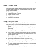
1 Chapter 1: Printer Setup This chapter contains important information on setting up your printer. Be sure to read this chapter carefully before using the printer for the first time.
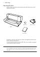
2 Printer Setup Unpacking the printer Check to make sure that the carton contains each of the items shown in the following illustration. Platen knob Ribbon cartridge Printer Users manual If anything is missing, contact the store where you bought the printer and ask them to supply the missing part. A serial-to-parallel interface converter (SPC-8K) is also available as an option. Consult with your dealer for details.
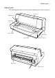
General guide 3 General guide The following illustrations show the major component parts of the your printer.
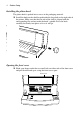
4 Printer Setup Installing the platen knob The platen knob is packed into a recess in the packaging material. ❏ Install the knob on the shaft located inside the large hole on the right side of the printer. Make sure that the flat side of the shaft is aligned with the corresponding flat surface inside the knob’s spindle. Press the knob carefully but firmly into place as far as it will go.
Installing the ribbon cartridge 5 Installing the ribbon cartridge ❏ Make sure that printer is unplugged from its power outlet. ❏ Open the front cover of the printer. ❏ By hand, move the cartridge holder to the center position of the paper guide where there is a cutout to allow easy installation and removal of the ribbon cartridge. Cartridge holder Important! Never try to move the print head while the printer is plugged into a power outlet. Doing so can damage the printer.
6 Printer Setup ❏ Carefully place the cartridge onto the cartridge holder making sure that the spindle of the holder fits into the socket on the bottom of the cartridge. ❏ Press down gently but firmly on the cartridge until it snaps securely into ❏ ❏ place. Rotate the knob on the cartridge again to take up any slack. Close the front cover of the printer. Important! Printing that is poor quality or too light is almost always due to a ribbon that is simply worn out or “used up.
Connecting to a power outlet and turning power on and off 7 ❏ By hand, move the cartridge holder to the center position of the paper guide where there is a cutout to allow easy installation and removal of the ribbon cartridge. Important! Never try to move the print head while the printer is plugged into a power outlet. Doing so can damage the printer. If you have just used the printer, let the print head cool for a few minutes before you touch it.
8 Printer Setup ❏ Set the switch on the front of the printer to ON to turn power on, and to OFF to turn power off. ON I OFF O Important! We recommend that you unplug the printer from the power outlet whenever you do not plan to use it for long periods. Because of the this, you should locate the printer so that the power outlet it is plugged into is nearby and easy to access. At this point you may want to perform a test of the printer to make sure it is working properly.
Loading paper 9 ❏ Set the release lever on the back of the printer to the fanfold position. Fanfold Cut-sheet Release lever ❏ Set the adjustment lever to the value that matches the thickness of the paper you are using. The setting for normal paper is 1. Set the lever to a larger value for thicker paper, or to a smaller value for thinner paper. See the table on page 27 for details.
10 Printer Setup Note that there is a guide inside the printer in front of the left tractor. The ▼ mark of the guide indicates where the left margin of the printing will be. ❏ Once the left tractor is aligned the way you want it, push the gray lever ❏ back down to lock it in place. Now move the tractor on the right to the approximate position of the right side of the paper you are using. Pull its gray lever up to unlock it, and push the lever back down to lock it into place.
Loading paper ❏ Press the control panel’s SET/EJECT/PARK button and the paper will feed to the starting position.
12 Printer Setup Printing on fanfold paper When printing on fanfold paper, take care not to print too close to the perforations that separate each sheet. The following shows the recommended print area for fanfold paper and cut-sheet paper. Fanfold paper Cut-sheet paper 4 mm (0.16") 4 mm (0.16") 18 mm (0.7") 18 mm (0.7") 5 mm (0.2") Perforation Bottom of Form 4 mm (0.16") 4 mm (0.16") 5 mm (0.2") 6 mm (0.25") 6 mm (0.
Unparking fanfold paper 13 ❏ Set the release lever on the back of the printer to the cut-sheet position. The paper is now parked, and you can load cut-sheet paper into the printer using the procedures under “Manual sheet feeding” on page 27. Unparking fanfold paper After you are finished printing on cut-sheet paper, use the following procedure to unparkin fanfold paper and make it available for printing.
14 Printer Setup Connecting to your computer The computer sends data to the printer through a cable. This printer does not come with a cable, so you must purchase one of your own. You will probably want to use a standard parallel cable for connection, but note that you can also use an optional serial-to-parallel interface converter (SPC-8K). Important! The following instructions apply to the Centronics parallel cable that is used with an IBM-compatible personal computer.
Connecting to your computer ❏ Plug the other end of the parallel cable into the socket on the side of the printer and secure it in place with the clips. Note: Consult with your dealer for details on how to set up your computer when using the optional SPC-8K serial-to-parallel interface converter.
16 Chapter 2: Control Panel Operations The control panel gives you push-button control over the printer’s power and paper feed operations. It also includes indicator lights that tell you the current status of the printer at a glance. POWER NLQ MICRO FEED SET/EJECT LINE PARK FEED ON LINE FORM FEED This chapter describes general functions that can be performed using the control panel buttons while the printer is turned on and either on-line or off-line.
Paper loading 17 Paper loading ❏ Prepare either cut-sheet or fanfold paper for feeding. ❏ ❏ For details on how to prepare for paper feeding, see page 8 for fanfold paper and page 27 for cut-sheet paper. The POWER indicator flashes to indicate there is no paper in the printer. Press SET/EJECT/PARK to feed the paper into the printer. Line feed ❏ Make sure the printer is off-line (ON LINE indicator is not lit). ❏ Press LINE FEED once to feed paper one line.
18 Control Panel Operations Parking fanfold paper ❏ Make sure the printer is off-line (ON LINE indicator is not lit). ❏ Press SET/EJECT/PARK to eject the paper. ❏ After the paper is ejected, the printer will beep and the POWER indicator will flash to indicate there is no paper in the printer. ❏ Later, you can press SET/EJECT/PARK again to feed the paper back into the printer. Micro feed Use the following operation to feed the paper in very small increments.
Setting the printing speed 19 Setting the printing speed ❏ Make sure the printer is on-line (ON LINE indicator is lit). ❏ Press the control panel’s LINE FEED button to switch between NLQ (NLQ indicator is lit) and draft (NLQ indicator is not lit) printing. NLQ printing provides high quality, but is somewhat slower. Draft printing is quicker, but the quality is not as good as NLQ. Tear-off function This procedure feeds fanfold paper to a position where it can be torn off easily.
20 Chapter 3: Using the EDS Mode The letters “EDS” stand for “Electronic DIP Switches.” Just like the small DIP switches that are used by many computers, printers, and other devices, the EDS lets you configure the printer so that it matches your system and software needs. This chapter describes how to enter the printer’s EDS Mode and provides details about available settings and how to change them.
Entering the EDS Mode 21 Entering the EDS Mode ❏ Turn off the printer. ❏ Make sure that paper is loaded in the printer. ❏ While holding down the control panel’s SET/EJECT/PARK button, turn the printer back on. This causes the following message to be printed. Note: The paper is not fed after the message is printed, so you will have to open up the printer’s front cover to read it. ❏ Press SET/EJECT/PARK to answer “Yes” or LINE FEED to answer ❏ ❏ “No” for each option as it appears on the printout.
22 Using the EDS Mode EDS Mode Settings RAM Usage ❏ Specify whether RAM should be used as an input buffer or as a download buffer. Selecting Input Buffer tells the printer to use available RAM to store data it receives from the computer. This speeds up the printing operation, but it also means that RAM cannot be used to store character patterns used to define down loaded characters.
EDS Mode Settings 23 Paper Out ❏ Enable or disable the paper out detect function. When paper out detection is set to Enabled, the printer automatically stops printing whenever it senses there is no more paper. When set to Disabled, the printer continues printing as long as there is data. Selecting Disabled makes it possible to print right up to the bottom of a page, but it also creates the danger of printing when there is no paper loaded in the printer, which can damage the print head and platen.
24 Using the EDS Mode Banking Character ❏ Enable or disable banking character font. When the banking character is set to Enabled, the printer uses a special banking font to print the dollar sign and numerals 0 through 9. When set to Disabled, the special banking font is not used. Zero style ❏ Select the type of zero you want to use. Selecting Normal prints zeros without lines running through them, while Slashed prints zeros with a diagonal slash running through them.
25 Chapter 4: Paper Handling Your printer is designed to print on a variety of different paper types. This chapter tells you everything you need to know about paper, and how to set the printer up for manual paper feed. In this chapter, you will learn about: ❏ ❏ ❏ ❏ Selecting the best type of paper to use Adjusting for paper thickness Manual sheet feeding Clearing paper jams Selecting paper types Use the following information when selecting paper. Cut-Sheet Paper Width: 5.
26 Paper Handling Adjusting for paper thickness Paper comes in different weights, normally expressed as gsm (grams per square meter) or lbs (pounds). Some form paper also has multiple pages that make them quite thick. Use the following procedure to change the gap between the print head and the platen and adjust for paper thickness. 7 Adjustment lever 5 3 1 ❏ Move the adjustment lever to one of its nine settings. Position 1 is most suitable for single-sheet paper.
Automatic fanfold feeding 27 The following table provides a general guide for setting the adjustment lever. Experiment with different settings until you find the one that gives you the print quality you want. Weight Per Sheet Thickness Recommended Position 14 lbs (52 gsm) 0.06 mm 1 17 lbs (64 gsm) 0.08 mm 1 21 lbs (81 gsm) 0.10 mm 1 28 lbs (104 gsm) 0.13 mm 1 42 lbs (156 gsm) 0.19 mm 2 2-ply 11 lbs (40 gsm) 0.13 mm 2 3-ply 11 lbs (40 gsm) 0.20 mm 3 4-ply 11 lbs (40 gsm) 0.
28 Paper Handling ❏ Set the release lever on the back of the printer to the cut-sheet position. Fanfold Cut-sheet Release lever ❏ Set the adjustment lever to the value that matches the thickness of the paper you are using. The setting for normal paper is 1. Set the lever to a larger value for thicker paper, or to a smaller value for thinner paper. 7 5 3 1 ❏ Adjust the paper guide to the position you want.
Manual sheet feeding 29 Note that the ▼ mark of the guide indicates where the left margin of the printing will be. Paper guide Scale ❏ Making sure that the left edge of the paper is against the paper guide, insert a sheet of paper into the front of the printer. Paper guide Paper Table ❏ Press the control panel’s SET/EJECT/PARK button once to feed the paper into the printer. ❏ Start the printing operation from your software application.
30 Paper Handling Note: If you are inserting letterhead paper, insert the sheet so that it is face up with the letterhead portion up. Clearing paper jams Use the following procedure to clear paper jams from the printer. ❏ Unplug the printer from its AC power outlet. ❏ Open the front cover of the printer. ❏ Carefully try to pull the jammed paper from the printer. ❏ If necessary, move the release lever on the back of the printer to the fanfold position or rotate the platen knob to remove the paper.
31 Chapter 5: Using the Printer with MS-DOS This chapter contains information about how to use the printer with applications software running under MS-DOS. In this chapter, you will learn about: ❏ How to set up for printing with MS-DOS Setting up for printing with MS-DOS To print from an application running under MS-DOS, you must first select the printer from within the application. Typically, the program will feature an INSTALL or SETUP command for selection of printers.
32 Appendix A: Troubleshooting The appendix tells you what you need to know if you experience problems with your printer. It tells you how to test the printer, how to check system software settings, and how to adjust the vertical alignment. In addition, there is information on actions to take for specific problems, and on the meanings of printer beep tones. Warning! The printer uses high voltage. Do not attempt any other repair or maintenance except as expressly recommended in this appendix.
33 Hexadecimal dump This procedure prints in hexadecimal format all codes (character codes and control codes) that are sent to the printer by the computer. The printer does not execute any control codes (such as 0A - linefeed), it just prints them out. The hexadecimal dump is useful when you are writing programs for printer control. ❏ Turn off the printer. ❏ Make sure that paper is loaded in the printer.
34 Troubleshooting ❏ If the three lines do not align properly, use SET/EJECT/PARK to move ❏ ❏ ❏ the middle line to the left or LINE FEED to move it to the right. The above step performs alignment for DRAFT mode only. You must make separate adjustments for the D-DENSITY/SPEED, NLQ, NORMALDENSITY, PLOTTER GRAPHICS, CRT GRAPHICS-1, CRT GRAPHICS-II, and DOUBLE-DENSITY modes as well. Press ON LINE to change to another printing mode.
35 Problem Possible Cause Recommended Action Printer test works, but printer will not print out data from the attached computer. Your application program’s or system software’s printer selection is wrong. Check the printer selection of your application software. The computer’s system software is not set up properly for the printer or for the type of interface cable you are using. Check the system software settings. The interface cable is connected incorrectly or damaged.
36 Troubleshooting Problem Lines print over each other. Incorrect number of lines are printed on the page. Text and graphics are malformed. Possible Cause Recommended Action Auto line feed with carriage return is disabled by the EDS setting. Use the EDS Mode to enable auto line feed with carriage return. See “Auto LF with CR” on page 22. Jamming paper. Set up the printer for the paper thickness you are using. See “Adjusting for paper thickness” on page 26.
37 Problem Forms are smudged. Printing is too dark. Printer prints past the edge of the paper. Possible Cause Recommended Action The printer is not set up correctly for the thickness of paper being used. Set up the printer for the paper thickness you are using. See “Adjusting for paper thickness” on page 26. The ribbon is jammed, twisted, or not set correctly between the print head and the print head shield. Make sure that the ribbon cartridge is installed correctly.
38 Troubleshooting Problem Left margin moves to the right during printing. Some characters are printed incorrectly. Possible Cause Recommended Action The paper is not loaded correctly, causing the print head to jam. Remove all paper from the printer and reload it. Try printing again. The ribbon cartridge is not installed correctly, causing the print head to jam. Make sure that the ribbon cartridge is installed correctly. See “Installing the ribbon cartridge” on page 5.
39 Problem Printer behaves erratically. Printing suddenly stops. Possible Cause Recommended Action The interface cable is connected incorrectly or damaged. Check to make sure that the printer interface cable is connected correctly. If it is, try a different cable. Static electricity caused by interference from nearby electrical devices or by lowlevel humidity is affecting printer operation.
40 Troubleshooting To check the port ❏ Double-click the Control Panel icon in the Main window. ❏ Double-click the Printers icon. ❏ Double-click on the name of your Star printer in the list of installed printers. ❏ Click on Connect. ❏ Make sure that your printer cable is connected to the port highlighted in the ❏ ❏ list of ports. If you are using a parallel cable, you will probably be using LPT1. If you are using the optional serial-to-parallel interface converter, you should be using COM1 or COM2.
41 Appendix B: Specifications Printing System Printing Speed Print Direction Print Head Line Spacing Character Matrix Environment Paper Serial Impact Dot-Matrix Pitch Draft (cps/dpi) NLQ (cps/dpi) Pica (10 cpi) 180/120H 45/240H Elite (12 cpi) 216/120H 54/240H Condensed pica (17 cpi) 154/240H 77/240H Condensed elite (20 cpi) 180/240H 90/240H H: half-dot Draft: Bi-directional logic seeking NLQ: Uni-directional or bi-directional logic seeking (selectable); Default: bi-directional Bit-Image: Uni-directio
42 Emulation Maximum Buffer Size Interface Ribbon Type Ribbon Life Dimensions and Weight Power Supply Power consumption Options Copies: Original + 6 ESC/P Without download: 15.2 kB With download: 0.5 kB Standard: Centronics parallel Option: RS-232C serial On-carriage, dedicated Monochrome (X9): Black only 2 million characters (ASCII Draft) Width: 20.67″ / 525 mm Depth: 14.57″ / 370 mm Height: 9.06″ / 230 mm Weight: 16.1 lbs. / 7.
43 Appendix C: Interface Pin Outs Parallel Interface Pin Name Function 1 2 3 4 5 6 7 8 9 10 11 12 13 14-15 16 17 18 19 - 30 31 32 33 34 - 36 STROBE DATA0 DATA1 DATA2 DATA3 DATA4 DATA5 DATA6 DATA7 ACK BUSY PAPER SELECT Goes low for ≥0.5µs when active. These signals represent information for the 1st through 8th bit of parallel data, respectively. Each signal is HIGH when data is logical 1, and LOW when logical 0. SIGNAL GND CHASSIS +5V GND RESET ERROR EXT GND 10µs low to acknowledge receipt of data.
44 Appendix D: Character Sets Character Set #2 (Graphics Character Table) Character Set #2 (Italic Character Table)
45 Character Set #1 Other characters are the same as those for Character Set #2, above. International Character Set The character codes shown in the table are hexadecimal.
46 Printer Control Codes Appendix E: Printer Control Codes This appendix lists the printer’s control commands. It gives the name of each control command and the applicable ASCII code.
47 Top/Bottom Margin and Vertical Tab Commands Description ASCII Code Advance paper to next vertical tab position VT Reverse feed paper one line ESC LF Select VFU channels ESC /n Set vertical tab positions ESC Bn…NULL Set bottom margin ESC Nn Cancel bottom margin ESC O Set VFU in a channel ESC bnm…NULL Special Print Mode Commands Description ASCII Code Set master print mode ESC! Cancel underlining ESC-0 Select underlining ESC-1 Select emphasized print ESC E Cancel emphasized print
48 Printer Control Codes Line Spacing Commands Description ASCII Code Advance paper one line (line feed) LF Reverse paper one line ESC LF Set line spacing to 1/8″ ESC 0 Set line spacing to 7/72″ ESC 1 Set line spacing to 1/6″ ESC 2 Set line spacing to n/216″ ESC 3n Set line spacing to n/72″ ESC An One time feed of n/216″ ESC Jn One time reverse feed of n/216″ ESC jn Form Feed and Related Commands Description ASCII Code Advance paper to top of next page (form feed) FF Set page lengt
49 Horizontal Print Position Control Commands Description ASCII Code Move print head to next horizontal tab position HT Return print head to left margin (carriage return) CR Move print head to absolute horizontal position ESC $ n1 n2 Add n dot spaces between characters ESC SPn Set horizontal tab positions ESC Dn…NULL Set right margin ESC Qn Move print head to specified horizontal position ESC \ n1 n2 Left justification ESC a0 Centering ESC a1 Right justification ESC a2 Set left margin
50 Glossary Appendix F: Glossary Centronics cable Parallel cable normally used to connect the printer to the computer. control code A numeric code that instructs the computer to perform an operation. For example, the computer sends the printer a form feed control code (12) to tell it to eject the current page. Electronic DIP Switch settings Printer settings that take effect when you switch on the printer. You can make these settings using the control panel.
A D adjusting dot alignment 33 adjustment lever 26, 27 application printer selection checking 39 Auto LF with CR 22 AUTOEXEC.
printing on 12 specifications 25 tear-off function 13, unparking 13 form feed 17 front cover opening 4 N 19 44 H hexadecimal dump 33 I input buffer 22 interface pin outs optional serial interface 43 parallel interface 43 International Character Set 45 Italic Character Table 44 L line feed 17 Line Spacing 23 O G glossary 50 Graphics Character Table Graphics Direction 22 NLQ 23 M manual sheet feeding 27 micro feed 18 MS-DOS setting up for printing 31 system software settings 40 off-line switching
printer control codes 46 printing problem 35 problems causes and solutions 34 dark printing 37 erratic operation 39 excessive noise 35 hot printer case 36 incorrect characters 38 left margin movement 38 line spacing 35 malformed graphics 36 no printing 34 overprinting lines 36 paper feed 35 power supply 34 print quality 36 printing past paper edge 37 smudged forms 37 sudden stoppage 39 wrong number of lines 36 T Tear-off 22 tear-off function 13, test print 8, 32 top of form clearing 18 setting 18 troublesh
Customer service information If you experience any technical difficulties with your Star printer, please refer to Appendix A How to deal with printing problems. This chapter describes easy methods to diagnose and resolve some of the problems which you may encounter. For further technical support, you should first contact your Authorized Star Dealer. If you require additional support, Star Micronics offers a wide variety of technical support services.