USER’S MANUAL LC-8521 DOT MATRIX PRINTER
CE Manufacturer's Declaration of Conformity EC Council Directive 89/336/EEC of 3 May 1989 This product, has been designed and manufactured in accordance with the International Standards EN 50081-1/01.92 and EN 50082-1/01.92, following the provisions of the Electro Magnetic Compatibility Directive of the European Communities as of May 1989.
About this manual This manual describes how to set up, use, and care for the Star LC-8521 printer. The following is a list of what you can expect to find in each chapter.
Contents Chapter 1: Printer Setup ... 1 Choosing a place for the printer ... 1 Unpacking the printer ... 2 General guide ... 3 Removing the protective materials ... 4 Installing the platen knob ... 5 Opening the front cover ... 5 Installing the ribbon cassette ... 6 Removing the ribbon cassette ... 7 Connecting to a power outlet and turning power on and off ... 9 Loading fanfold paper ... 10 Printing on fanfold paper ... 14 Parking fanfold paper ... 15 Unparking fanfold paper ...
Saving a macro ... 26 Clearing the printer’s buffer ... 26 Initializing the printer ... 27 Entering the Multi-part Mode ... 27 Chapter 3: Using the EDS Mode ... 28 About EDS Mode settings ... 28 Entering the EDS Mode ... 28 Selecting a bank ... 29 Selecting a switch ... 30 Changing a switch setting ... 30 Printing the current switch settings ... 30 Exiting the EDS Modes ... 30 EDS Modes Settings ... 30 EDS-1 Settings ... 31 Chapter 4: Using the Printer with Windows 3.1 ...
Chapter 7: Paper Handling ... 57 Selecting paper types ... 57 Adjusting for paper thickness ... 58 Automatic fanfold feeding ... 59 Manual sheet feeding ... 60 Clearing paper jams ... 62 Chapter 8: Optional Accessory ... 63 Serial-to-Parallel Converter (SPC-8K) ... 63 Connecting the Interface Converter ... 64 Setting the converter’s DIP switches ... 65 Push Tractor Unit (CT-15HA) ... 67 Removing the push tractor unit from the back of the printer ... 68 Installing the push tractor unit ...
Appendix F: Glossary ... 102 Appendix G: Control Panel Operation Guide ...
1 Chapter 1: Printer Setup This chapter contains important information on setting up your printer. Be sure to read this chapter carefully before using the printer for the first time.
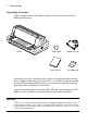
2 Printer Setup Unpacking the printer Check to make sure that the carton contains each of the items shown in the following illustration. Printer Platen knob Ribbon cassette , User s manual 3.5" Floppy disk If anything is missing, contact the store where you bought the printer and ask them to supply the missing part. Note that it is a good idea to keep the original box and all the packing materials just in case you need to pack the printer up again and send it somewhere at a later date.
General guide General guide The following illustrations show the major components of your printer.
4 Printer Setup Removing the protective materials Two packing materials are inserted into the printer to protect components during shipping. Before using the printer, be sure to remove all packing materials from inside the front cover and the document table as shown in the illustration.
Installing the platen knob 5 Installing the platen knob The platen knob is packed into a recess in the packaging material. ❏ Install the knob on the shaft located inside the large hole on the right side of the printer. Make sure that the flat side of the shaft is aligned with the corresponding flat surface inside the knob’s spindle. Press the knob carefully but firmly into place as far as it will go.
6 Printer Setup Installing the ribbon cassette ❏ Make sure that the printer is unplugged from its power outlet. ❏ Open the front cover of the printer. ❏ By hand, move the cartridge holder to the center position of the paper guide where there is a cutout to allow easy installation and removal of the ribbon cassette. Cartridge holder Important! Never try to move the print head while the printer is plugged into a power outlet. Doing so can damage the printer.
Removing the ribbon cassette 7 ❏ Press down gently but firmly on the cassette until it snaps securely into ❏ ❏ place. Rotate the knob on the cassette again to take up any slack. Close the front cover of the printer. Important! Printing that is poor quality or too light is almost always due to a ribbon that is simply worn out or “used up.” If you experience problems with print quality, check the condition of the ribbon. If the black part looks gray and well-worn, replace the ribbon with a new one.
8 Printer Setup Important! Never try to move the print head while the printer is plugged into a power outlet. Doing so can damage the printer. If you have just used the printer, let the print head cool for a few minutes before you touch it. ❏ Using your thumb and forefinger to squeeze the two tabs on the ribbon cassette towards the center, carefully remove the cassette from the holder. ❏ Use the procedure under “Installing the ribbon cassette” on page 6 to install a new cassette.
Connecting to a power outlet and turning power on and off 9 Connecting to a power outlet and turning power on and off ❏ Lift up the back of the printer and insert two books or other similar objects ❏ underneath it to keep the printer raised and connect the power cord. Plug the power cord of the printer into a standard power outlet whose voltage matches the power rating noted on the label affixed to the bottom of your printer.
10 Printer Setup Caution! Whenever you turn off the power, wait at least five seconds before turning it back on; otherwise you may damage the printer. We recommend that you unplug the printer from the power outlet whenever you do not plan to use it for long periods. Because of the this, you should locate the printer so that the power outlet it is plugged into is nearby and easy to access. At this point you may want to perform a test of the printer to make sure it is working properly.
Loading fanfold paper 11 Important! To protect against paper jams, make sure that the fanfold paper is stacked in a position that is lower than the printer. To decrease paper jams, be sure that the perforations cannot catch on anything in the paper path. ❏ Unplug the printer from its AC power supply. ❏ Pull the release lever on the Front of the printer to the fanfold position. ❏ Set the adjustment lever to the value that matches the thickness of the paper you are using.
12 Printer Setup ❏ Unlock the tractor on the left (when viewing the printer from behind) by pulling its blue lever up, and adjust the position of the left tractor. Note that there is a guide inside the printer in front of the left tractor. The ▲ mark of the guide indicates where the left margin of the printing will be. ❏ Once the left tractor is aligned the way you want it, push the blue lever ❏ back down to lock it in place.
Loading fanfold paper 13 ❏ Plug the printer back into its AC power source. The printer will beep a number of times to indicate that paper is not loaded. ❏ Press the control panel’s PAPER FEED button and the paper will feed to the starting position.
14 Printer Setup Printing on fanfold paper When printing on fanfold paper, take care not to print too close to the perforations that separate each sheet. The following shows the recommended print area for fanfold paper, cut-sheet paper, Labels and Envelope. Fanfold paper Cut-sheet paper 4 mm (0.16") 4 mm (0.16") *1 First page 5 mm (0.2") 4 mm (0.16") 4 mm (0.16") Perforation 5 mm (0.2") 4 mm (0.16") 18 mm (0.7") 18 mm (0.7") *1 : When stapled multi-part paper with a width of less than 4.
Parking fanfold paper 15 Parking fanfold paper It is not necessary to remove fanfold paper currently loaded in the printer in order to print on cut-sheet paper fed by hand. Instead, simply use the following procedure to park the fanfold paper. ❏ Tear off the paper at a perforation so there is no more than half a page ❏ ❏ ❏ sticking out of the front cover of the printer. If necessary, you can press the control panel’s ON LINE button to put the printer off-line.
16 Printer Setup ❏ Tear off the paper. ❏ When you resume printing, the printer reverse feeds the paper to its former position. Connecting to your computer with a parallel cable The printer is equipped with a parallel interface as standard. It does not come with a cable, so you must separately purchase one that matches the needs of your computer. You will probably want to use a standard parallel cable when connecting to the printer’s parallel interface.
17 Important! Make sure that the printer is unplugged from the AC outlet and that the computer is turned off before connecting them. ❏ Plug one end of the parallel cable into the parallel port of your computer. ❏ ❏ The parallel port should be labeled “Printer,” “Parallel,” “PRN,” “LPT1,” or something similar.
18 Printer Setup Connecting to your computer with a serial cable The printer is equipped with a serial interface as standard. It does not come with a cable, so you must separately purchase one that matches the needs of your computer. You will probably want to use a standard serial (RS-232C) cable when connecting to the printer’s serial interface. The printer is also equipped with a parallel interface (page 16).
Connecting to your computer with a serial cable 19 ❏ Plug one end of the serial cable into the serial port of your computer. The parallel port should be labeled “COM1,” “COM2,” or something similar. ❏ Lift up the back of the printer and insert two books or other similar objects ❏ underneath it to keep the printer raised. Plug the other end of the serial cable into the socket on the back of the printer and secure it in place with the screws.
20 Control Panel Operations Chapter 2: Control Panel Operations The control panel gives you push-button control over the printer’s operations. It includes indicator lights, which tell you the current status of the printer at a glance.
Selecting a font 21 Selecting a font ❏ Make sure the printer is off-line (ON LINE indicator is not lit). ❏ Press FONT to change the font selection. An indicator lights to the left of the name of the font that is currently selected.
22 Control Panel Operations Setting the character pitch The character pitch setting controls how many characters are printed per inch. Use the following procedure to select the pitch you want. ❏ Make sure the printer is off-line (ON LINE indicator is not lit). ❏ Press PITCH to change the pitch selection. The following shows the meanings of the indicators that light on the control panel when you press PITCH.
23 Line feed ❏ Make sure the printer is off-line (ON LINE indicator is not lit). ❏ Press PAPER FEED once to feed paper one line. Holding down PAPER FEED continually feeds paper, one line at a time, until you release the button. Paper eject (cut-sheet paper) ❏ Make sure the printer is off-line (ON LINE indicator is not lit). ❏ Press PARK/SET/EJECT to eject the paper. ❏ After the paper is ejected, the printer will beep and the POWER indicator will flash to indicate there is no paper in the printer.
24 Control Panel Operations Setting the top of form position The current position of paper loaded in the printer is automatically set as the top of the page whenever you turn power on. You can also use the following procedure at any time to specify a different position as the top of the page. ❏ Make sure the printer is off-line (ON LINE indicator is not lit). ❏ Use the micro feed operations (see above) to move the paper so that the print head is located where you want the new top of form position to be.
Changing the auto load position 25 Changing the auto load position Normally the printer automatically feeds paper to a standard position (1/6-inch from the top of the paper). This is called the auto load position. You can use the following procedure to specify a different auto load position. ❏ Make sure the printer is off-line (ON LINE indicator is not lit). ❏ While holding down ON LINE, press PITCH and then release the two ❏ ❏ ❏ ❏ buttons.
26 Control Panel Operations Saving a macro Normally, any settings you make on the control panel are cleared when you turn the printer off. Use the following procedure to save the current control panel settings so that they are used whenever you turn the printer on. ❏ Make the control panel settings you want. ❏ Use ON LINE to put the printer off-line (ON LINE indicator is not lit). ❏ Hold down FONT and then PITCH. Keep both buttons held down until the ❏ printer beeps twice.
Initializing the printer 27 Initializing the printer The following procedure initializes the printer to its power-on settings. If you have control panel settings stored in memory, this procedure sets up the printer using them. ❏ Use ON LINE to take the printer off line (ON LINE indicator is not lit). ❏ Hold down FONT and then PAPER FEED.
28 Using the EDS Mode Chapter 3: Using the EDS Mode The letters “EDS” stand for “Electronic DIP Switches.” Just like the small DIP switches that are used by many computers, printers, and other devices, the EDS lets you configure the printer so that it matches your system and software needs. This chapter describes how to enter the printer’s EDS Mode and provides details about available settings and how to change them.
Selecting a bank 29 Note: The contents of the above message are the same, regardless of whether you enter EDS-1 or EDS-2. The asterisks indicate the current EDS Mode switch settings for all the banks in both sub-modes. Selecting a bank ❏ While in the EDS Modes (EDS-1 or EDS-2), use the control panel’s BANK button to select a bank. While the BANK indicator is flashing, the lit indicator indicates the currently selected bank.
30 Using the EDS Mode Selecting a switch ❏ While in the EDS Modes (EDS-1 or EDS-2), use the control panel’s SWITCH button to select a bank switch. While the SW indicator is flashing, the lit indicator indicates the currently selected switch. Lit Indicator Selected Switch A1 1 B2 2 C3 3 D4 4 E5 5 F6 6 Changing a switch setting ❏ After selecting a bank and switch, press the control panel’s ON/OFF button to turn the switch on and off.
EDS-1 Settings 31 EDS-1 Settings The following details all of the settings you can make for EDS-1. BANK A Switch 1: Emulation Selects Standard emulation (ON) or IBM emulation (OFF). Standard emulation causes the printer to act like the Epson ESC/P (24-pin), while IBM emulation makes it act like the IBM Proprinter XL24E. Switch 2: Character Table The function of this switch depends on whether you are using IBM or Standard emulation.
32 Using the EDS Mode When Auto (SW5: ON and SW6: ON) is selected, the printer mode automatically switches between Multi-part Mode and Normal Mode. For example, if the adjustment lever is set to 3 or less, Normal Mode is selected; if the lever is set to 4 or more, Multi-part Mode is selected. Mode SW5 SW6 Auto selectable ON ON Multi-part mode OFF ON Normal mode ON OFF BANK B Switch 1: Graphics Direction Selects uni-directional (OFF) or bi-directional (ON) printing for graphics.
EDS-1 Settings 33 BANK C Switches 1, 2: Print Mode Turn these switches on or off to select the print mode you want to use. Print Mode SW1 SW2 LQ ON ON Draft OFF ON HS-Draft ON OFF Switches 3, 4, 5: Print Pitch Turn these switches on or off to form the pattern that matches the print pitch setting you want to make.
34 BANK D Switches 1, 2, 3, 4: Page Length Turn these switches on or off to form the pattern that matches the Page Length setting you want to make. Page Length SW1 SW2 SW3 SW4 11”/Letter ON ON ON ON 8” OFF ON ON ON 11.7”/A4 ON OFF ON ON 12” OFF OFF ON ON 8.5”/Letter ON ON OFF ON 14”/Legal OFF ON OFF ON 10.5”/Executive ON OFF OFF ON 7.25”/Executive OFF OFF OFF ON 3.5” ON ON ON OFF 5.
EDS-1 Settings Code Page SW1 SW2 SW3 SW4 SW5 SW6 #437 IBM-PC ON ON ON ON ON ON #850 Multi-lingual OFF ON ON ON ON ON #860 Portuguese ON OFF ON ON ON ON #861 Icelandic OFF OFF ON ON ON ON #863 Canadian French ON ON OFF ON ON ON #865 Nordic OFF ON OFF ON ON ON #866 Russian ON OFF OFF ON ON ON OFF OFF OFF ON ON ON #3840 IBM-Russian #3841 Gost-Russian ON ON ON OFF ON ON #3843 Polish OFF ON ON OFF ON ON #3844 CS2 ON OFF ON OFF ON
36 Using the EDS Mode Code Page SW1 SW2 SW3 SW4 SW5 SW6 #3860 Rajvitee KU ON ON ON ON ON OFF #3861 Microwiz KU OFF ON ON ON ON OFF #3863 STD 988 TIS ON OFF ON ON ON OFF #3864 Popular TIS OFF OFF ON ON ON OFF #3865 Newsic TIS ON ON OFF ON ON OFF A code page is the set of symbols and characters that your printer can print. Your printer converts ASCII hexadecimal data according to a code page to print symbols and characters.
EDS-1 Settings Code Page Name #852 Latin-2 #1001 Arabic #737 Country 37 Remarks Croatia, Czech Republic, Hungary, Poland, Romania, Serbia, Slovak Republic, Slovenia Preferred by Microsoft Egypt, Saudi Arabia Mainly in Arabic speaking countries Greek Greece Almost 80% #851 Greek Greece #869 Greek Greece #928 Greek Greece For UNIX #2001 Lithuanian-KBL Lithuania Commonly used for DOS #772 Lithuanian Lithuania New standard #774 Lithuanian Lithuania #3001 Estonian-1 Eston
38 Using the EDS Mode If your EDS settings specify Standard emulation (Bank A, Switch 1 ON) with the italic character table (Bank A, Switch 2 OFF), use the Bank E switches to select the international character set you want to use. This setting determines the assignment of 14 character codes in the Standard Italic character set. International Character Set SW1 SW2 SW3 SW4 SW5 SW6 U.S.A.
EDS-2 Settings 39 BANK F Switches 1, 2, 3, 4, 5, 6: LQ Font Selection Turn these switches on or off to form the pattern that identifies the font you want to use for LQ printing.
40 Switch 2: Parity Check This switch specifies whether or not a parity check should be performed on the data. Parity Check SW2 DOS/Windows Setting Disabled ON Disabled Enabled OFF Enabled Switch 3: Parity This switch specifies the parity as non, odd, or even.
EDS-2 Settings 41 BANK B Switch 1, 2, 3: Baud Rate The baud rate is the speed, in bits per second, that the printer sends data to the computer. The common setting is 9600 or 19200. Baud Rate SW1 SW2 SW3 DOS/Windows Setting 300 OFF OFF OFF 300 600 ON OFF OFF 600 1200 OFF ON OFF 1200 2400 ON ON OFF 2400 4800 OFF OFF ON 4800 9600 ON OFF ON 9600 19200 OFF ON ON 19200 Switch 4: Not used Switch 5, 6: Waiting period for paper loading Waiting period SW1 SW2 2.
42 Using the Printer with Windows 3.1 Chapter 4: Using the Printer with Windows 3.1 This chapter contains specific information you need to know when using the printer with Microsoft Windows 3.1 or later. It also tells you how to install the printer driver on your computer so that it can control the printer correctly. In this chapter, you will learn about: ❏ ❏ ❏ ❏ ❏ How to set up for printing with Microsoft Windows 3.
Setting up for printing with Microsoft Windows 3.1 ❏ ❏ ❏ ❏ 43 Click Add and the dialog box will expand to show a List of Printers. In the List of Printers: box, select Install Unlisted or Updated Printer. Click Install. This causes the Install Driver dialog box to appear, which instructs you to insert the disk that contains the printer driver file. ❏ Click Browse. ❏ In the Directories: list, select WIN 31. ❏ Click on the language you want to use and then click OK.
44 Using the Printer with Windows 3.1 ❏ In the List of Printers: box of the Add Unlisted or Updated Printer ❏ ❏ dialog box, select your printer driver and then click OK. This causes the Printers dialog box to appear. Your printer is now listed in the Installed Printers: list. Double-click on the name of the printer model you just installed to select it as the default printer. Click Close to close the Printers dialog box.
Printing a document 45 ❏ From this window you select buttons that let you control a wide variety of ❏ ❏ printer setup parameters. This manual does not include any information about how to do this because everything you need to know is included in an on-line manual that tells you how to use all the buttons and menus that appear. To view the on-line manual, click on the Help button. After the printer is set up the way you want it, click on OK.
46 Using the Printer with Windows 3.1 Note: The actual appearance of the Print window may differ somewhat depending on the application you are using. Use this window to specify the range of the pages to be printed, the quality of the printing (in dots per inch), and the number of copies you want to print. Note also that there are boxes that you can select to specify printing to a file or collating (printing from back to front). You can change the printer setup by clicking on the Setup button.
47 ❏ Insert the disk that contains the fonts into one of your computer’s disk ❏ ❏ ❏ drives. This explanation assumes you are using a drive named “A:”, but you could use any drive. Just remember to change the “A:” in the following steps to the name of the drive you are using. Select the letter that represents the drive where the floppy disk is installed. When you do, the names of all the fonts on the disk appear in the List of Fonts window. Select the fonts you want to install by clicking on their names.
48 Using the printer with Windows 95 Chapter 5: Using the printer with Windows 95 This chapter describes how to use the printer with Microsoft Windows 95. The following topics are covered: ❏ ❏ ❏ ❏ Setting up the printer in Windows 95 Preparing for printing Printing a document Installing the TrueType fonts Note: The file “readme.txt” on the floppy disk contains any late-breaking information that has been made available since this manual was printed.
49 ❏ When the above window is displayed, make sure the Local printer radio button is checked. Then click on the Next button. ❏ Click on the Next button and click on the Back button. Then click on the ❏ ❏ Have Disk button. Insert the disk with the printer driver file on it into the floppy disk drive. Make sure that the drive’s name (“A:” or “B:”) is displayed in the field named Copy manufacturer’s files from:.
50 ❏ Click on the OK button twice. ❏ Select the language or language group you want to use by clicking on it. ❏ Select the printer model name (“Star LC-8521”) by clicking on it and then click on the Next button. ❏ Select the printer port to which the printer is connected by clicking on it (usually “LPT1”). Click on the Next button. ❏ Change the printer name if you want. If you have previously installed another printer, you must select whether you want the new printer to be the default printer.
Preparing to print 51 Note: Windows applications always print to the currently selected default printer, unless the user chooses a different printer from within the application. ❏ Click on the Next button. ❏ Select whether to print out a test page by clicking on the appropriate radio ❏ ❏ ❏ ❏ button. Click on the Finish button. If a message appears requesting you to insert the Windows 95 CD-ROM, insert it into the CD-ROM drive and click on the OK button.
52 Using the printer with Windows 95 ❏ Double-click on the icon bearing the name of the printer (Star LC-8521) in ❏ ❏ ❏ the Printers window. A window appears listing any documents that are currently being printed on the printer. Click on the Printer menu. To set the printer as the default printer, click on the Set As Default command so that a tick mark appears in the check box. This denotes that the selected printer is the default printer. Click on the Printer menu and click on the Properties command.
Printing a document 53 This concludes the printing preparation. The printer which you selected is now the default printer, and the page size, paper source setting and any other settings which you made for the printer, apply to printing from all applications. To override these settings for a specific application, refer to the next section, Printing a document. Printing a document Windows 95 applications always print to the currently selected default printer.
54 Using the printer with Windows 95 ❏ Select how many copies of the document will be printed by entering the appropriate number into the Number of copies field. If you want to print all the pages in your document, make sure that the All radio button is checked. If you do not want to print all the pages in your document, enter the first and last pages to print into the from and to fields.
Installing TrueType fonts 55 ❏ Select the fonts you wish to install by clicking on them. If you want to install all of them, click on the Select All button. ❏ Click on the OK button. The new fonts can now be seen in the Fonts folder window. This concludes the font installation.
56 Using the Printer with MS-DOS Chapter 6: Using the Printer with MS-DOS This chapter contains information about how to use the printer with applications software running under MS-DOS. In this chapter, you will learn about: ❏ How to set up for printing with MS-DOS ❏ How to select fonts from within an application Setting up for printing with MS-DOS To print from an application running under MS-DOS, you must first select the printer from within the application.
57 Chapter 7: Paper Handling Your printer is designed to print on a variety of paper types. This chapter tells you everything you need to know about paper, and how to set the printer up for manual paper feed. In this chapter, you will learn about: ❏ ❏ ❏ ❏ Selecting the best type of paper Adjusting for paper thickness Manual sheet feeding Clearing paper jams Selecting paper types Use the following information when selecting paper. Cut-Sheet Paper Width: 2″ to 16.5″ / 51 to 420 mm Length: 2.
58 Paper Handling Labels Backing sheet: 3″ to 16″ / 76 to 406 mm Thickness: Backing sheet 0.0028″ to 0.0035″ / 0.07 to 0.09 mm Total thickness 0.0075″ / 0.19 mm * Use labels only under normal temperature and humidity conditions. Envelope #10: 9.4″ × 4.1″ / 240 × 104 mm #6: 6.5″ × 3.6 ″ / 166 × 92 mm Adjusting for paper thickness Paper comes in different weights, normally expressed as gsm (grams per square meter) or lbs (pounds). Some types of forms have multiple pages that make them quite thick.
59 The following table provides a general guide for setting the adjustment lever. Experiment with different settings until you find the one that gives you the print quality you want. Weight Per Sheet Thickness Recommended Position 14 lbs (52 gsm) 0.06 mm 1 17 lbs (64 gsm) 0.08 mm 1 21 lbs (81 gsm) 0.10 mm 1 28 lbs (104 gsm) 0.13 mm 1 42 lbs (156 gsm) 0.19 mm 2 2-ply 11 lbs (40 gsm) 0.13 mm 2 3-ply 11 lbs (40 gsm) 0.20 mm 3 4-ply 11 lbs (40 gsm) 0.
60 Paper Handling Manual sheet feeding You can use the following procedure to manually feed cut-sheet paper into the printer. ❏ Make sure that there is no fanfold paper in the printer. If there is, use the ❏ procedure under “Parking fanfold paper” on page 15 to park the fanfold paper and prepare for manual sheet feeding. Set the release lever on the front of the printer to the cut-sheet position. ❏ Set the adjustment lever to the value that matches the thickness of the paper you are using.
61 ❏ Adjust the paper guide to the position you want. Note that the ▼ mark of the guide indicates where the left margin of the printing will be. Paper guide Scale ❏ Making sure that the left edge of the paper is against the paper guide, insert straight a sheet of paper into the front of the printer as far as it will go. The paper will automatically be fed into the printer. Paper guide Paper Table ❏ Start the printing operation from your software application.
62 Paper Handling Note: If you are inserting letterhead paper, insert the sheet so that it is face up with the letterhead portion up. Clearing paper jams Use the following procedure to clear paper jams from the printer. ❏ ❏ ❏ ❏ ❏ Turn the power off. Unplug the printer from its AC power outlet. Open the front cover of the printer. Carefully try to pull the jammed paper from the printer.
63 Chapter 8: Optional Accessory This chapter explains how to connect and set up the following optional accessories that are available for this printer: ❏ Serial-to-Parallel Converter (SPC-8K) ❏ Push Tractor Unit (CT-15HA) Important! Always make sure that printer power is turned off whenever installing or removing optional accessories. Serial-to-Parallel Converter (SPC-8K) Connecting the serial-to-parallel converter to the printer’s parallel connector provides a second serial connection.
64 Connecting the Interface Converter ❏ Unplug the printer from its AC power outlet. ❏ Set the DIP switches on the SPC-8K to the settings you want to use before ❏ you connect it to your printer. See the following section for details on how to set the DIP switches Plug the interface converter’s Centronics connector into the socket on the side of the printer and secure it in place with the clips.
Setting the converter’s DIP switches 65 Important! ❏ Make sure that the serial-to-parallel converter is resting on a stable, level surface where it will not be subject to vibration or damage. [CORRECT METHOD] [INCORRECT METHOD] Setting the converter’s DIP switches You should set the converter’s DIP switches so they match the settings you make on your computer. The table to the right shows the parameter that each DIP switch on the serial-to-parallel converter controls.
66 Optional Accessory Data Length Switch 1 Data Length DOS/Windows Setting ON 8 bits 8 OFF 7 bits 7 Parity Switch 2 Switch 5 Parity DOS/Windows Setting ON ON or OFF None N OFF ON Odd O OFF OFF Even E Protocol Switch 3 Switch 4 Protocol ON ON DTR ON OFF XON/XOFF OFF ON ETX/ACK Baud Rate Switch 6 Switch 7 Switch 8 Baud Rate DOS/Windows Setting OFF OFF OFF 150 bps 150 OFF OFF ON 300 bps 300 OFF ON OFF 600 bps 600 OFF ON ON 1200 bps 1200 ON OFF O
Push Tractor Unit (CT-15HA) 67 Push Tractor Unit (CT-15HA) The printer comes with a push tractor unit pre-installed for back-to-front feeding of fanfold paper. You can use the push tractor unit as it is, or you can move it to the front of the printer for front-to-back feeding. Users who find themselves having to frequently move the push tractor unit between the front and back may wish to purchase an optional CT-15HA Push Tractor Unit.
68 Optional Accessory Removing the push tractor unit from the back of the printer ❏ Make sure that the printer is unplugged from its AC power source. ❏ Open the cover where the push tractor unit is located. ❏ If the push tractor unit is located in the back of the printer, open the back cover. If it is located in the front of the printer, open the document table. In either case, opening the cover as far as it will go will cause it to lock in place.
Installing the push tractor unit 69 Installing the push tractor unit ❏ Make sure that the printer is unplugged from its AC power source. ❏ Open the cover where you want to install the push tractor unit. ❏ If you want to install the push tractor unit in the back of the printer, open the back cover. If you want to install it in the front of the printer, open the document table. In either case, opening the cover as far as it will go will cause it to lock in place.
70 Troubleshooting Appendix A: Troubleshooting The appendix will provide help if you experience problems with your printer. It tells you how to test the printer, how to check system software settings, and how to adjust the vertical alignment. In addition, there is information on actions to take for specific problems, and on the meanings of printer beep tones. Warning! The printer uses high voltage. Do not attempt any other repair or maintenance except as expressly recommended in this appendix.
Hexadecimal dump 71 Note: Test printing prints across the entire width of the carriage. Make sure that the printer is loaded with the widest paper available in order to avoid damage to the print head and platen. Hexadecimal dump This procedure prints in hexadecimal format all codes (character codes and control codes) that are sent to the printer by the computer. The printer does not execute any control codes (such as 0A - linefeed), it just prints them out.
72 Troubleshooting ❏ While holding down the control panel’s PARK/SET/EJECT and ON LINE buttons, turn the printer back on to enter the Dot Adjustment Mode. The printer will print something like the following. *** DOT ADJUSTMENT SETTING *** Normal-density 0: Note that the printer will feed the paper forward and back each time during this operation so you can view the printout. ❏ If the two lines do not align properly, use FONT to move the lower line to ❏ ❏ ❏ the left or PITCH to move it to the right.
Troubleshooting guide 73 Troubleshooting guide Use the following table to help track down the causes of problems and to determine the best solution to deal with them. Problem The ON LINE indicator does not light. Possible Cause The printer is not receiving power. Recommended Action Check whether the power cord is correctly plugged into the power outlet. Check whether the power outlet is working by unplugging the printer and plugging in another device. Printer sounds like it is printing, but it is not.
74 Troubleshooting Problem Possible Cause Recommended Action Printer test works, but printer will not print out data from the attached computer. The interface cable is connected incorrectly or damaged. Check to make sure that the printer interface cable is connected correctly. If it is, try a different cable. Printer does not feed paper properly. Jamming paper. Remove all paper from the printer and then reload it. The printer is not set up correctly for the thickness of paper being used.
Troubleshooting guide Problem Possible Cause Incorrect number of lines are printed on the page. Auto line feed with carriage return is enabled. Use the EDS Mode to disable auto line feed with carriage return (page 32). The line spacing or leading selected by your application program is wrong. Choose a different line spacing or leading setting from your application. Dot adjustment is not correct. See “Adjusting the dot alignment” on page 71. Text and graphics are malformed.
76 Troubleshooting Problem Possible Cause Recommended Action Printer case is hot. The printer’s air vents are blocked or obstructed. Switch off the printer and let it cool. Check the air vents on the bottom of the printer to see if they are blocked. Remove the obstruction if possible. If the problem persists, return the printer to your dealer for repair. Printer makes excessive noise. The front cover is removed. Replace the front cover. The printer is vibrating.
Troubleshooting guide Problem Left margin moves to the right during printing. Some characters are printed incorrectly. Possible Cause 77 Recommended Action The paper is not loaded correctly, causing the print head to jam. Remove all paper from the printer and reload it. Try printing again. The ribbon cassette is not installed correctly, causing the print head to jam. Make sure that the ribbon cassette is installed correctly. See “Installing the ribbon cassette” on page 6.
78 Troubleshooting Problem Possible Cause Recommended Action Some characters are printed incorrectly. Inappropriate settings are selected by your application program. Choose different settings in your application. Wires are missing from the print head. Return the printer to your dealer for repair. The interface cable is connected incorrectly or damaged. Check to make sure that the printer interface cable is connected correctly. If it is, try a different cable.
Checking system software settings in Windows 79 Checking system software settings in Windows Whenever you have problems printing from a Windows application, you should check the following four things: ✓ ✓ ✓ ✓ Is the printer you are using set as the default printer? Is the drive setup correctly? Is the printer you are using correctly selected in your application? Is the correct port selected? You should also refer to your Microsoft Windows User’s Guide for other information that might be helpful.
80 Troubleshooting To check the application printer selection ❏ Select Print from the application’s File menu, and a window appears listing available printers. ❏ Check to see that the name of your printer is selected. If it is not, select it and try printing from your application again. To check the port ❏ Double-click the Control Panel icon in the Main window. ❏ Double-click the Printers icon. ❏ Double-click on the name of your printer in the list of installed printers. ❏ Click on Connect.
Checking system software settings in MS-DOS 81 Appendix B: Specifications Printing System Printing Speed Print Direction Print Head Line Spacing Character Matrix Environment Serial Impact Dot-Matrix Pitch HS-Draft (cps/dpi) Draft (cps/dpi) LQ (cps/dpi) Pica (10 cpi) 400/80H 300/120H 100/360H Elite (12 cpi) 360/120H 120/360H Semi-condensed (15 cpi (S)) 450/120H 150/360H Semi-condensed (15 cpi (I)) 225/240H 150/360H Condensed pica (17 cpi) 255/240H 170/360H Condensed elite (20 cpi) 300/240H 198/360H 24
82 Specifications Paper Cut-sheet Paper width: Paper length: Paper weight (1-ply): Multi-part: Copies: Fanfold Paper width: Paper length Paper weight (1-ply): Multi-part: Emulation Interface Ribbon Type Ribbon Life Dimensions and Weight Power Supply Power Consumption Options 2″ to 16.5″ / 51 to 420 mm 2.75″ to 14″/ 70 to 356 mm 14 to 42 lbs / 52 to 156 g/m2 / 45 to 135 kg 11 to 14 lbs / 40 to 52 g/m2 / 34 to 45 kg; pressure sensitive paper Total thickness: 0.014″ / 0.
Checking system software settings in MS-DOS 83 Appendix C: Interface Pin Outs Parallel Interface Pin Name Function 1 2 3 4 5 6 7 8 9 10 11 12 13 14 15 16 17 18 19 - 30 31 32 33 34 - 35 36 STROBE DATA0 DATA1 DATA2 DATA3 DATA4 DATA5 DATA6 DATA7 ACK BUSY PAPER SELECT AFXT Goes low for ≥0.5µs when active. These signals represent information for the 1st through 8th bit of parallel data, respectively. Each signal is HIGH when data is logical 1, and LOW when logical 0.
84 Character Sets Appendix D: Character Sets Standard Italic Character Set International Character Set The character codes shown in the table are hexadecimal.
85 IBM Character Set #2 Code Page #437 (IBM-PC) Character Set #1 Other characters are the same as those for Character Set #2.
86 Character Sets IBM Special Character Set The following characters can be printed using the ^ command. Code Page #850 Multi-lingual Other characters are the same as those for Code Page #437. Code Page #860 Portuguese Other characters are the same as those for Code Page #437. Code Page #861 Icelandic Other characters are the same as those for Code Page #437.
87 Code Page #863 Canadian French Other characters are the same as those for Code Page #437. Code Page #865 Nordic Other characters are the same as those for Code Page #437. Code Page #866 Russian Other characters are the same as those for Code Page #437. Code Page #3840 IBM-Russian Other characters are the same as those for Code Page #437.
88 Character Sets Code Page #3841 Gost-Russian Other characters are the same as those for Code Page #437. Code Page #3843 Polish Other characters are the same as those for Code Page #437. Code Page #3844 CS2 Other characters are the same as those for Code Page #437. Code Page #3845 Hungarian Other characters are the same as those for Code Page #437.
89 Code Page #3846 Turkish Other characters are the same as those for Code Page #437. Code Page #3847 Brazil-ABNT Other characters are the same as those for Code Page #437. Code Page #3848 Brazil-ABICOMP The other characters are the same as in code page #437. Code Page #852 Latin-2 Other characters are the same as those for Code Page #437.
90 Character Sets Code Page #1001 Arabic Code Page #737 Greek Other characters are the same as those for Code Page #437. Code Page #851 Greek Other characters are the same as those for Code Page #437.
91 Code Page #869 Greek Other characters are the same as those for Code Page #437. Code Page #928 Greek Other characters are the same as those for Code Page #437. Code Page #2001 Lithuanian-KBL Other characters are the same as those for Code Page #437. Code Page #772 Lithuanian Other characters are the same as those for Code Page #437.
92 Character Sets Code Page #774 Lithuanian Other characters are the same as those for Code Page #437. Code Page #3001 Estonian1 Other characters are the same as those for Code Page #437. Code Page #3002 Estonian2 Other characters are the same as those for Code Page #437. Code Page #3011 Latvian1 Other characters are the same as those for Code Page #437.
93 Code Page #3012 Latvian2 Other characters are the same as those for Code Page #437. Code Page #3021 Bulgarian Other characters are the same as those for Code Page #437. Code Page #3031 Hebrew Other characters are the same as those for Code Page #437. Code Page #3041 Maltese Other characters are the same as those for Code Page #437.
94 Character Sets Code Page #3850 Standard KU Other characters are the same as those for Code Page #437. Code Page #3860 Rajvitee KU Other characters are the same as those for Code Page #437. Code Page #3861 Microwiz KU Other characters are the same as those for Code Page #437. Code Page #3863 STD988 TIS Other characters are the same as those for Code Page #437.
95 Code Page #3864 Popular TIS Other characters are the same as those for Code Page #437. Code Page #3865 Newsic TIS Other characters are the same as those for Code Page #437.
96 Printer Control Codes Appendix E: Printer Control Codes This appendix lists the printer’s control commands. It gives the name of each control command, along with the applicable emulation mode (Standard, IBM, or Both), and the applicable ASCII code.
97 Print Pitch Control Commands Description Select one line expanded print Mode ASCII Code Both SO Same as SO STD ESC SO Select condensed print Both SI Same as SI STD ESC SI Cancel condensed print STD DC2 Set print pitch to pica IBM DC2 Cancel one-line expanded print Both DC4 Set print pitch to elite IBM ESC : Set print pitch to elite STD ESC M Set print pitch to pica STD ESC P Cancel proportional print IBM ESC P00H Select proportional print IBM ESC P01H Cancel expanded
98 Printer Control Codes Special Print Mode Commands Description Set master print mode Mode ASCII Code STD ESC! Cancel underlining Both ESC-0 Select underlining Both ESC-1 Select emphasized print Both ESC E Cancel emphasized print Both ESC F Select double-strike print Both ESC G Cancel double-strike print Both ESC H Select superscripts Both ESC S0 Select subscripts Both ESC S1 Cancel super/subscripts Both ESC T Cancel upperlining IBM ESC _0 Select upperlining IBM ESC _
99 Line Spacing Commands Description Advance paper one line (line feed) Mode ASCII Code Both LF Reverse paper one line STD ESC LF Set line spacing to 1/8″ Both ESC 0 Set line spacing to 7/72″ IBM ESC 1 Set line spacing to 1/6″ STD ESC 2 Execute ESC A IBM ESC 2 Set line spacing to n/180″ (STD/IBM), n/216″ (IBM), or n/360″ (IBM) Both ESC 3n Set line spacing to n/360″ STD ESC +n Set line spacing to n/60″ STD ESC An Define line spacing to n/72″ IBM ESC An One time feed of n/180″
100 Printer Control Codes Horizontal Print Position Control Commands Description Mode ASCII Code Move print head to next horizontal tab position Both Return print head to left margin (carriage return) Both CR Move print head to absolute horizontal position STD ESC $n1 n2 Add n dot spaces between characters STD ESC SPn Cancel automatic line feed IBM ESC 5 00H Select automatic line feed IBM ESC 5 01H Set horizontal tab positions Both ESC Dn …NULL Set right margin STD ESC Qn Set lef
101 Other Commands (Continued) Description Select uni-directional printing Mode ASCII Code Both ESC U1 Control character height, width, line spacing IBM ESC [@ Set initial condition IBM ESC [K Select 1 x 1, 2 x 2, 4 x 4 sized printing STD ESC hn Stop printing IBM ESC j Select type face STD ESC kn Cancel double-high mode STD ESC w0 Select double-high mode STD ESC w1 NEC Commands Description Mode ASCII Code Set line spacing to n/360″ STD FS 3n Initialize printer STD FS @ Sel
102 Glossary Appendix F: Glossary adjustment lever Controls the darkness of the printing by adjusting for the thickness of the paper you are printing on. Centronics cable Parallel cable normally used to connect the printer to the computer. control code A numeric code that instructs the printer to perform an operation. For example, the computer sends the printer a form feed control code (12) to tell it to eject the current page.
Checking system software settings in MS-DOS 103 Appendix G: Control Panel Operation Guide POWER HS-DRAFT DRAFT ROMAN SANSERIF COURIER PRESTIGE ORATOR BANK SW A1 D4 10 CPI 12 CPI 15 CPI B2 E5 COND C3 F6 PROP PARK PAPER SET/EJECT FEED ON LINE FONT PITCH BANK SW ON/OFF EDS PRINT EXIT Font Selection Pitch Selection Set/Eject/Park Line Feed On-Line Panel Macro Form Feed Back ward Forward Micro Feed Set TOF Auto Loading Position Change Mode Buffer Clear & All Reset Quiet Mode OFF
A application printer selection checking 80 auto LF with CR 32, 41 auto load position changing 25 auto tear-off 32 AUTOEXEC.
E G EDS Mode changing a switch setting glossary 102 graphics direction 32 30 default settings 28 definition 28 entering 28 exiting 30 printing current switch settings 30 selecting a bank 29 selecting a switch 30 settings 30, 31, 39 using 28 eject 23 Electronic DIP Switches 28 emulation 31 F fanfold paper automatic feeding 59 form feed 23 loading 10 parking 15, 23 perforations 14 printing on 14 specifications 57 tear-off function 15, 24 unparking 15 font selecting 21 Font Lock Mode entering 21 form feed
excessive noise 76 hot printer case 76 incorrect characters 77, 78 left margin movement 77 line spacing 74 malformed graphics 75 no printing 73 overprinting lines 74 paper feed 74 power supply 73 print quality 75 printing past paper edge 76 smudged forms 75 sudden stoppage 78 weak printing 73 wrong number of lines 75 ON-LINE indicator 20 on-line switching to 20 options serial-to-parallel converter 63 P paper fanfold 14 handling 57 letterhead 62 micro feed 23 recommended print area 14 selecting 57 setting
troubleshooting 70 guide 73 TrueType fonts installing 46 U unidirectional printing 32 unpacking 2 W Windows 3.
Customer service information If you experience any technical difficulties with your Star printer, please refer to Appendix A How to deal with printing problems. This chapter describes easy methods to diagnose and resolve some of the problems that you may encounter. For further technical support, you should first contact your Authorized Star Dealer. If you require additional support, Star Micronics offers a wide variety of technical support services.