MULTI-FONT LC24-15 USERS MANUAL NOT INTENDED FOR SALE
Self Declaration Radio interference regarding this equipment has been eliminated according to Vfg 1046/1984 announced by the DBP. DBP has been informed of the introduction of this special equipment and has been granted the right to examine the whole series. It is the user’s responsibility to see that his own assembled system is in accordance with the technical regulations under Vfg 1046/1984. To conform to FTZ-regulations it is necessary to make all connections to the printer with shielded cable.
HOW TO USE THIS MANUAL This manual is organized into nine chapters. To learn how to make the best use of your printer you are urged to read through chapters 1 through 3. The remaining chapters may be treated as a reference guide for programming operations, etc. It assumes a degree of acknowledge off the operation of computers (for instance, it assumes you know about hexadecimal numbers).
Chapter 6 - MS-DOS and your printer Since the PC or PC-AT family of computers running under MS-DOS is currently the most popular configuration of microcomputer, we have included a few hints and tips to help you use your printer with such systems. Since virtually all PCs are sold with a Microsoft BASIC interpreter, we have also included some hints, and a sample program in this language to demonstrate the capabilities of the printer.
FEATURES OF THE PRINTER This printer is a convenient, monochrome printer without frills but with a full complement of features, making it an excellent partner for a personal computer. It supports the IBM/Epson printer commands and character sets, enabling it to print just about anything your computer can generate, both text and graphics.
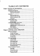
TABLE OF CONTENTS Chapter 1 SETTING UP THE PRINTER ...............................................1 Locating the Printer .......................................................................... 1 Unpacking and Inspection ................................................................ 2 Cheek the carton contents ........................................................ 2 Parts name of the printer .......................................................... 3 Setting Up .......................................
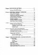
Chapter 3 DIP SWITCH SETTINGS .. .. .. . . .. .. ... .. .. .. .. ... .. .. .. . . .. . .. ... . .. .. . 31 Location of the DIP Switches .... .................................. .. ................. 31 Functions of the DIP Switches ........................................ ............... 32 Chapter 4 PRINTER CONTROL COMMANDS ..................... .. ......... 37 Font Control Commands .............. .. ............................... ................. 38 Character Set Commands .................................
Chapter 8 SPECIFICATIONS ................................................................ 107 Chapter 9 CHARACTER SETS ............................................................. 111 Standard Character Set .................................................. .. ... .... ...... 112 IBM Character Set #2 .......................... .. ............ ... .. ...................... 114 IBM Character Set #l .......................... ............ ....... .. .................... 116 IBM Special Character Set .........
Chapter I SETTING UP THE PRINTER Subjects covered in Chapter 1 include l Locating the printer l Unpacking and inspection (names of parts) l Setting up and connection l Loading single sheets l Loading and parking fanfold forms l Adjusting the printing gap LOCATING THE PRINTER Before you start unpacking and setting up your printer, make sure that you have a suitable place on which to locate it.
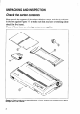
UNPACKING AND INSPECTION Check the carton contents Now unpack the contents of the printer shipping carton, and check each item in the box against Figure l-l to make sure that you have everything (there should be five items). If any of these items are missing, contact your supplier. F/gum I-1. Check 10 make sure you have all five items: 1) Printer, 2) Paper guide, 3) Platen knob, 4) Ribbon cartridge, and 5) User’s manual.
The optional accessories which you may have ordered with your printer are: l l l l l Serial (RS-232) interface board Automatic sheet feeder Pull tractor unit Font card RAM card Parts name of the printer Make an external inspection of the printer. Note the locations of the following parts: Entry slot Release lever Power Figure 7-Z. The printer’s external parts Bail lever: opens and closes the paper bail which holds the paper against the platen. Release lever: releases the platen.
SETTING UP Place the printer in the position where it is going to be permanently sited, and remove all packing material from inside the top cover. This packing material is intended to prevent damage to the printer in transit. You may like to keep this packing with the printer carton if you intend transporting the printer for use at a different location. Mount the platen knob The platen knob is packed into a recess of the white foam packing material which held your printer inside the printer carton.
Figure T-4. Removing the top cover 1. Use the tensioning knob on the ribbon cartridge to tighten the ribbon if it is slack (turn clockwise). 2. Use the grips on the side of the ribbon cartridge to help locate the cartridge (squeeze them inwards gently), and make sure that the spindles on the cartridge holder fit into the sockets on the cartridge itself. Figure 1-5.
3. The ribbon should pass between the print head and the print head shield (see Figure l-6). Figum i-6. Pass the ribbon between the print head and print head shield Now, hold the top cover upright and engage the tabs at the back. Then swing the front edge down until the cover is closed. Leave the top cover closed during normal operation. It keeps out dust and dirt and reduces the printer’s operating sounds. Open the cover only to change the ribbon or make an adjustment.
Install the optional IC card This printer has five built-in character styles (fonts), and an1 1 K-byte data buffer. You can add more fonts or expand the data buffer by installing oprional IC cards (Font card or RAM card). To install or change an IC card, first turn off the power switch. Then, insert the IC card into the slot at the bottom right front of the printer and slide it all the way in. Figure 1-7. Slide the IC card into the front slot with the power switch off.
Connection Connect the printer to your computer, using a standard parallel-type cable. On a PC or PC/AT-type computer, this means that you use the 25way Dtype connector at the computer end, and the Amphenol-type 36-way connector at the printer end. The pinouts of the printer’s connector are given in Chapter 8 if you need a cable for connection to another computer. Plug the printer into a suitable mains outlet. However, DO NOT turn on the power switch at the front of the printer yet.
Figure 1-9.
LOADING SINGLE SHEETS This section will take you through the procedures for loading single sheets of paper. If you are using the optional automatic sheet feeder (ASF), read the ASF instruction booklet. Automatic loading Single sheets can be loaded manually with power off, or automatically with power on. We will start the easy way with automatic loading. 1. Place the paper guide in position, locating the lugs on the bottom of the assembly into the slots on the rear cover of the printer. Figure 7-70.
3. Adjust the paper guides to match the size of paper you will be using (remembering that printing will start some distance from the left-hand edge of the carriage). 4. Place a single sheet between the guides, placing the side on which you want to print towards the back of the printer. Gently push the paper down in the guides until you feel it stop. Adjustable paper guides lever I Figure 1-77. Loading a single sheet 5. Turn on the power using the switch at the front of the printer.
Manual loading It is also possible to load paper manually while the printer’s power is off. The procedure is: 1. Place the paper guide in position, locating the lugs on the bottom of the assembly into the slots on the rear cover of the printer. 2. Check that printer power is off and the release lever at the back of the printer is down. 3. Open the top cover, then move the bail lever on top of the printer forward to open the paper bail. 4.
LOADING AND PARKING FANFOLD FORMS Fanfold forms have holes along the sides and perforations between the sheets, They are also called sprocket forms, punched forms, or just plain “computer paper”. This printer accepts forms up to 16” wide. Fanfold forms are loaded, parked, and unparked as explained next. Loading the fanfold forms You can load the fanfold paper from the rear of the printer. 1. Place a stack of fanfold paper behind and at least one page-length below the printer. 2.
6. With the sprocket covers open, thread the paper over the sprockets, aligning holes with the pins on the sprockets. 7. Adjust the spacing of the sprockets by sliding them along the bar, using the clamp lever at the back of each sprocket to release and lock the sprocket in positin (when the lever is down, the sprocket may be moved, and when it is up, the sprocket is locked). Flgurs I-13. Thread the fanfold paper over the sprockets 8.
12. Mount the paper guide in the horizontal position shown in Figure 1-14, so that it will separate the printed from the unprinted paper. Figure I-14. Mounting the paper guide for fanfold forms Loading the paper with pull tractor unit You can load the fanfold paper by using the optional pull tractor unit. 1.
unit Platen igure l-15.Mounting the optional pull tractor unit - - pure 7-76. Thread the fanfold paper over the sprockets from the entry slot of the printer. 7. Now close the sprocket covers, again making sure that the paper sprocket holes are aligned with the pins on the sprockets. If they are not aligned properly, you will have problems with paper feeding, possibly resulting in tearing and jamming of the paper. 8. Mount the new top cover.
Paper parking After loading fanfold paper with the internal tractor unit, you do not have to unload it when you want to print on a single sheet. The printer will “park” it for you if you follow the procedure below. 1. Paper parking starts with power ON, fanfold paper loaded in printing position, the release lever up. 2. Press the ( ON LINE ) button on the control panel to set the printer offline (ON LINE indicator off). 3.
ADJUSTING THE PRINTING GAP The distance between the print head and the platen can be adjusted to accommodate different paper thicknesses. To make this adjustment, remove the top cover. The adjustment lever is located near the right end of the paper bail. Pulling the adjustment lever upwards narrows the gap; pushing it downwards widens the gap. There are five positions; you can feel the lever clicking into each position.
chapter 2 CONTROL PANEL OPERATIONS The control panel buttons can be pressed singly to perform the operations indicated by their names. Other functions can be obtained by holding these buttons down when you turn the printer’s power on. Still further functions can be executed by pressing the control panel buttons in combination. This chapter explains all the button and indicator functions. Pause printing Feed paper (fast and slow, forward and reverse) Park fanfold forms Set the top-of-form position .
ON LINE button The ( ON LINE ) button sets the printer on-line and off-line. The state changes each time you press the button. In the on-line state the printer receives data from the computer and prints the data. In the off-line state the printer stops printing and sends the computer a signal indicating that it cannot accept data. The printer powers up in the on-line state if paper is present. If paper is not present, the printer powers up off-line with the POWER indicator flashing.
PAPER FEED button If you press this button in off-line, the paper feeds forward. If you hold this button down, the printer performs consecutive line feeds. While you are feeding lines, if you also press the ( ON LINE > button, the paper will feed to the top of the next page. This is explained later. If you press this button in on-line, this will alternately illuminate and extinguish the QUIET indicator.
STYLE button This button selects the font style to be printed. Courier style is always selected at power-up. To change to one of the other styles, set the printer offline, then press the (~3) button repeatedly until the indicators beside the desired selection illuminate.
POWER-UP FUNCTIONS In addition to their normal functions, all the control panel buttons have special functions that operate if you hold them down while switching power on. 0 MICRO FEED POWER I --F-----A I Long test Short test Print area test Stay in panel style Stay in pAe1 Fbitch igufe 2-2. Power-up functions of control panel If the printer is turned on while the ( ON LINE ) button is pressed, the printer will enter the short self-test mode.
Long test mode If the printer is turned on while the (PAPER FEED] button is pressed, the printer will enter the long self-test mode. The printer will start printing as soon as the (PAPER FEED) button is released, and will print the version number of the printer’s ROM, followed by the whole character set printed in each font styles and pitch available. The test cycles endlessly. To stop the test you must switch power off.
Stay in panel style If held down during power-up, the (STYLE)button prevents software interference with the font style selected from the control panel. There will be an acknowledging beep, after which you can set the printer off-line, select a font style, then return to the on-line state and start printing. The selected font style will not be changed by any commands sent by software.
The following BASIC program is a simple test you can run in hexadecimal mode: 10 20 30 40 50 FOR I=0 TO 255 LPRINT CHR$(I); NEXT I LPRINT END If your system passes the codes directly to the printer without changing them, you will get a printout like Figure 2-4. 10001 0: IU “0 3 i, 40 5IJ <,U /u >u "0 1, 21 31 41 51 61 1, 81 ii, 12 22 ;,i 42 31 bi TL 3: 9~ to:, 04 t> 14 23 24 33 34 4j 44 53 54 o- 04 7: 74 5. ,,4 4.
When the IBM-PC BASIC interpreter sends hex code OD (carriage return) it adds an extra hex OA (line feed). Hex code 1A (end-of-file) also gets special treatment: the interpreter does not send it at all. This can cause problems that generate graphics or download character data, but there is a solution. Try changing line 20 in the preceding program and adding the coding shown below.
SWITCH COMBINATION FUNCTIONS Several additional functions can be obtained by pressing the control panel buttons in combinations, Top of form Clearing the buffer If you are using single sheets, this operation ejects the current page. If you are using fanfold forms, it feeds to the top of the next page. 1. PreSS the ( ON LINE ] button to set the printer off-line. 2. Pressthe (PAPER FEED) button and hold it down. The printer will start performing successive line feeds. 3.
Top of form When you turn on printer power, the top-of-form position is automatically set to the current position. If this is not where you want the top of the page to be, you can change the top-of-form position as follows. 1. Press the( ON LINE )button to set the printer off-line. 2. Move the paper to the desired top-of-form position by pressing the (PAPER FEED) button, orby performing a forward or reverse micro-feed. 3. Press and hold the ( ON LINE 1 button. 4. Press and hold the (PITCH)button. 5.
Clearing the buffer When DIP switch 2-l is ON, the printer stores received data in a large memory buffer. This creates a problem when you want to abandon a printing job and restart: the printer may be holding much more data in its buffer than it has actually printed, and this unprinted data must be cleared out before restarting. Turning power off is one way to clear the buffer, but there is another way: 1. Halt the printing program on the computer.
Chapter 3 D/P SWITCH SETTINGS The bank of DIP (Dual In-line Package) switches inside the printer is used for various functions. This chapter explains where the DIP switches are located, and how to use them. LOCATION OF THE DIP SWITCHES When you remove the printer’s cover and look inside, you will see on the green board at the bottom of the printer two groups of small white switches marked DSWl and DSW2. These arc the printer’s DIP switches. DSWl has eight switches, named 1-l to l-8 from Icft to right.
FUNCTIONS OF THE DIP SWITCHES The printer is delivered with all DIP switch set to the ON position. These are the standard settings. By changing the settings, you can alter various printer functions to match your requirements. The following questions will help you make the right settings. International character set Font style and pitch selection Switch l-l: Is the page length of your paper 11 inches or 12 inches? Leave this switch ON if you will be using 11-inch forms.
Switch l-3: Do you want a bottom margin? Leave this switch ON if you do not want to set the bottom margin. Move it to the OFF position if you want to set the bottom margin to the l-inch. Switch 1-4: Are you going to use the automatic sheet feeder (ASF)? To use the automatic sheet feeder, move this switch to the OFF position. Otherwise leave it ON.
Switch 1-8: Do you want an automatic line feed? If you leave this switch at the ON position, a separate line-feed code is required to obtain a line feed. If you move this switch to the OFF position, the printer performs both a carriage return and line feed each time it receives a carriage-return code. Most computer systems send a line feed code, or both a carriage return and line feed, at the end of each line, so this switch should be left ON.
I Switch 2-8: Which type of printing area format do you want to use for single sheets? This printer can use two types of printing area format for single sheets. By putting the switch ON (“A type”), the top of the first line of printing will start to one inch from the top of the paper, and the printed area will end to print 6 mm from the bottom of the paper.
-.
chapter 4 PRINTER CONTROL COMMANDS The printer has two emulation modes: Standard mode and IBM mode. In standard mode, the printer emulates the functions of the Epson LQ-1050. In IBM mode, the printer emulates the IBM Proprinter XL24. Additional command codes are included as a superset of these emulations. The emulation is changed by means of DIP switch l-6. When ON, the printer will be in standard mode, and when OFF, the printer will be in IBM emulation mode (see Chapter 3).
Many commands have alternative forms. Some commands use (character code 28) in IBM mode. Other commands have parameters that can be specified as either character codes or digit characters, like the parameter 1 in the sample command above. FONT CONTROL COMMANDS Select draft quality characters Mode ASCII &(.I 46 Both L‘( “ Decimal “F’ ‘.),, “x” “X” co> ,.).
n 0 1 2 3 4 Font style Courier (initial value) Optional font Prestige Orator script Select Courier characters Mode Both Decimal ASCII “(” “(.’ “F” “)” “)” Hexadecimal 40 40 70 41 41 48 “0” 28 28 46 29 29 30 Changes to the Courier font. Ignored if the (STYLE)button was pressed during power-up. Select Optional characters Mode Both Decimal ASCII “(” “(” “F” “)” “)” “1” Hexadecimal 40 40 70 41 41 49 28 28 46 29 29 31 Changes to the Optional font.
Select Script characters IMode 1 1 Both 1 ASCII “(.. “(” 1 Decimal “F’ “)” “)” 1 Hexadecimal 1 "4" 1 40 40 70 41 41 52 1 28 28 46 29 29 34 1 Changes to the Script font. Ignored if the (STYLE)button was pressed during power-up. Select italic characters Mode Both ASCII “(” Decimal “(” “I” “)” “)” “1” Hexadecimal 40 40 73 41 41 49 28 28 49 29 29 31 1B Std. “4” 27 52 1 IBM I “4” 1 28 52 34 I IC 34 1 Causes subsequent characters to be printed in italics.
Emphasized printing Mode ASCII Both Decimal Hexadecimal 27 69 “E” 1B 45 Causes subsequent characters to be emphasized by adding extra thickness to vertical strokes. Cancel emphasized printing Mode ASCII Both Hexadecimal Decimal 27 “F 1B 70 46 Cancels emphasized printing.
Stop underlining Mode ‘I (‘I Both Decimal ASCII ‘6(6‘ .,->. “)” “-” “0” “-I’ “).. “0” Hexadecimal 40 40 45 41 41 40 20 20 20 29 29 30 27 45 48 1B 2D 30 27 45 0 lB 2D 00 27 95 49 1B 5F 31 27 95 18 5F 01 Stops underlining. Start 0 verlining Mode Both Decimal ASCII “ _ “ “1” “p” cl> Hexadecimal 1 Causes subsequent characters to be overlined. Spaces skipped by horizontal tabulation are not overlined.
Cancel superscript or subscript Mode ASCII Both Decimal ‘T” 27 84 Hexadecimal 1B 54 Stops printing superscripts or subscripts and returns to normal printing. CHARACTER SET COMMANDS Select standard character set Selects the standard character set. This is the power-up default in Standard mode if DIP switch l-7 is ON. Select IBM character set Selects an IBM character set. This is the power-up default in IBM mode.
Select character set #2 Mode ASCII Both Decimal 27 54 “6” Hexadecimal 1B 36 Selects character set #2. Select international character set Mode ASCII Std. cESC> cFS> IBM Decimal Hexadecimal “R” n 27 02 n 18 52 II “R” II 20 02 n 1C 52 II .- Selects an international character set according to the value of n. n 0 1 2 3 4 5 6 Character set U.S.
Enable printing of all character codes on next character IMode 1 ASCII 1 IBM 1 ! ‘In,” Decimal 1 1 27 94 Hexadecimal 1 I 1 1B 5E This command operates like ‘T’ except that it remains in effect for only one character. Select slash zero IMode I Both ASCII I Decimal I Hexadecimal &SC> “ _ ” “1” 1 27 126 49 1 1B 7E 31 “ - 6’ 127126 1 1B 7E 01 1 I Causes subsequent zero characters to be overprinted with a slash (0).
Elite pitch Mode ASCII Decimal Hexadecimal Both “M” 27 77 1B 4D IBM cESC> 27 50 1B 3A “:” In Standard mode, changes from either pica or semi-condensed to elite pitch (12 cpi) or from condensed pica to condensed elite (20 cpi). In IBM mode, changes from either pica or condensed to elite (12 cpi). Ignored if the(ii)bu was pressed during power-up. High-speed elite pitch Mode ASCII Std.
Condensed printing IMode I Both ASCII I Decimal 1 27
- Expanded printing for one line Mode Both ASCII Decimal Hexadecimal 14 27 OE 14 18 OE Causes subsequent characters in the current line to be expanded to double width. Characters return to normal width after the next line feed (). The , , , and cESC> “w” 0 commands also cancel expanded printing.
Select fixed spacing Mode ASCII Both Decimal Hexadecimal “p” ‘VI” 27 112 40 1B 70 30 “D” co> 27 112 0 1B 70 00 “P” 12780 0 IlB 50 00 Causes subsequent characters to be printed with fixed character spacing. Ignored if the(piTR)button was pressed during power-up. Select master print mode Mode ASCII Both cESC> Decimal “!” 27 33 n Hexadecimal n 1B 21 n Selects a combined print mode according to the value of n.
Select double or quadruple size Mode ASCII Both Decimal “Y 27 104 n Hexadecimal n IlB 69 n Selects the size of subsequent characters as shown below. Extrahigh characters align along the cap-line of normal characters, with the base line temporarily moving down. Line spacing is temporarily doubled when n = 1 and quadrupled when n = 2. n 0 1 2 Effect Normal size Double-high, double-wide Quadruple-high, quadruple-wide Select character size (Mode 1 I Boti 1 I ASCII ,,(,, .&(&, ,,s,. ,.
Return to normal height Mode Both Std. Decimal ASCII “w” “0” Hexadecimal 27 119 40 18 1B “w” 27 119 “v” 20 86 48 “V” co> “0” 12886 1 0 77 30 77 00 56 30 0 pc IIC 56 00 I Terminates double-height printing and prints subsequent characters at normal height.
Select character type and print pitch Mode ASCII IBM Decimal “I” n 27 73 n Hexadecimal 1B 49 n Selects a combination of character type and print pitch according to the value of II as shown below. n 0 8 16 2 10 18 3 4 12 20 6 14 22 7 Character type Resident Draft Resident Draft Resident Draft Resident LQ Resident LQ Resident LQ Resident LQ Download Draft Download Draft Download Draft Download LQ Download LQ Download LQ Download LQ Ignored if the (STYLE)and/or cm) power-up.
VERTICAL POSITION COMMANDS Set line spacing to l/8 inch Mode ASCII Both Decimal 27 48 “0” Hexadecimal 1B 30 Sets the distance the paper advances or reverses in subsequent line feeds to l/8 inch. Set line spacing to 7/60 or 7/72 inch Mode ASCII Both Decimal Hexadecimal 1B 27 49 “I” 31 Sets the distance the paper advances or reverses in subsequent line feeds to 7/60 inch (standard mode) or 7/22 inch (IBM mode).
Set base unit for line spacing Mode ASCII IBM Decimal “[” ‘T’ CO> <4> CO> <0> n 27 91 92 0 Hexadecimal 4 0 18 58 5C On0 00 04 00 oonocl Sets the base unit for the line spacing commands, cESC> “3” and cESC> “J”. If the value of n is 180, the base unit is set to l/l 80”. If the value of n is 216, the base unit is set to l/216”. If otherwise specified, this command is ignored. This command becomes effective only after &SC> “3” or “J” is received.
Execute “A” Decimal “2” 27 50 Hexadecimal 1B 32 Sets the line spacing to the value defined by the last preceding Decimal Hexadecimal OA 10 Prints the current line and feeds the paper to the next line. If DIP switch 1-2 is ON, also moves the next print position to the left margin. See the preceding commands for the line spacing.
Perform one n/180-inch or n/2164nch line feed Mode ASCII Both Decimal “J’ 27 74 n Hexadecimal n jlB4A n Feeds the paper once by n/180 inches (standard mode) or n/2 16 inches, where n is between 1 and 255. Does not move the print position right or left when DIP switch l-2 is OFF. Does not change the line-spacing setting. Perform one n/216-inch reverse line feed Mode ASCII Std.
Set page length to n lines Mode ASCII Both cESC> Hexadecimal Decimal “c” n 27 67 1B n 43 n Sets the page length to n lines in the current line spacing, where n is between 1 and 127 in Standard mode or between 1 and 255 in IBM mode. Changing the line spacing later does not alter the physical page length. The current line becomes the top of the page.
Cancel top and bottom margins IModel ASCII 1 Both 1 Decimal 12 Hexadecimal oc Feeds the paper to the top of the next page according to the current page length, and moves the print position to the left margin. When the automatic sheet feeder (ASF) is selected (DIP switch l-4 is OFF), this command ejects the current page.
Set vertical tab stops Mode ASCII Both Decimal “B” nl n2 ... CO> Hexadecimal 27 66 nl n2 ... 1B 42 nl n2 ... 00 0 Cancels all current vertical tab stops and sets new vertical tab stops at lines nl, n2, etc., where nl, n2, etc. am numbers between 1 and 255. A maximum of 16 vertical tab stops can be set. The tab stops must be specified in ascending order, any violation of ascending order terminates the tab stop list. Standard termination is by the control code.
Vertical tab Mode ASCII Both Hexadecimal Decimal 11 OB Feeds the paper to the next vertical tab stop and moves the print position to the left margin. Performs a line feed if no vertical tabs are set, as at power-up. Feeds to the top of the next page if vertical tabs are set but the current line is at or below the last vertical tab stop.
Set right margin Mode ASCII Std. “Q” n 27 01 IBM “Q” n 20 Hexadecimal Decimal 81 n 1B 51 n n 1C 51 n Sets the right margin at column n in the current character pitch (pica pitch if proportional spacing is currently selected). Column n becomes the last character position in the line. The right margin does not move if the character pitch is changed later.
Set automatic line feed Mode IBM ASCII Decimal “5” 27 53 cl> Hexadecimal 1 1B 36 01 Causes the printer to perform both a carriage return and line feed each time it receives a code. This command takes priority over DIP switch 1-8. Cancel au toma tic line feed Mode IBM ASCII Decimal “5” CO> 27 53 Hexadecimal 0 1B 35 00 Causes the printer to perform only a carriage return when it receives a code. This command takes priority over DIP switch l-8.
Right justify Mode ASCII Both “a” “2” 27 97 50 1B 61 32 “a” c2> 27 2 1B 61 02 Decimal 97 Hexadecimal Aligns subsequent text with the right margin, leaving the left margin ragged. Full justify Mode ASCII Both “a” “3” 27 97 51 1B 61 33 cESC> “a” c3> 27 97 3 1B 61 03 Decimal Hexadecimal Aligns subsequent text between the left and right margins. Set horizontal tab stops Mode Both 3 ASCII Decimal "D" nl n2 ... CO> Hexadecimal 27 68 nl n2 ...
Reset all tab stops Mode ASCII IBM Decimal Hexadecimal 27 82 “R” 1B 52 Resets the horizontal tab stops to their power-up values in which a tab stop is set every 8 column starting at column 9. Also clears all vertical tab stops. Horizontal tab Mode ASCII Both Decimal Hexadecimal 9 09 Moves the print position to the next horizontal tab stop. Ignored if there is no next horizontal tab stop in the current line.
Absolute horizontal tab in inches Mode ASCII Both cESC> Decimal ‘3” nl Hexadecimal 27 36 nl n2 n2 lB 24 nl n2 Sets the next print position to (nl + n2 x 256)/60 inches from the left margin on the current line. Ignored if this position is beyond the right margin. The maximum position is 13.6 inches.
Print 8-bit double-density, double-speed graphics Mode Both ASCII cESC> Decimal ‘7” nl n2 m2 ml ... Hexadecimal 27 89 nl n2 ml m2 ... 1B 59 nl ml n2 m2 ... Prints bit-image graphics at 120 dots per inch horizontally (maximum 1632 dots wide), skipping every second dot in the horizontal direction. See cESC> “K” for other information. Print 8-bit quadruple-density graphics Mode Both ASCII Decimal “Z” n1 n.2 ml m2 ... Hexadecimal 27 90 nl ni’ ml m2 . . .
Select graphics mode Mode Both Decimal ASCII cESC> “*” n0 n2 nl ml m2 Hexadecimal 27 42 n0 nl ... n2 ml m2 1B 2A n0 nl ... n2 ml m2 ... Selects one of eleven graphics modes depending on the value of nO and prints dot graphics in this mode. See “2” (for 24-bit graphics) for information on nl, n2, ml, m2, ...
Se/ect graphics mode Mode IBM ASCII Decimal “[” “g” m0 nl n2 ml m2 ... 27 91 103 nl Hexadecimal n2 1B 58 67 nl n2 m0 ml m2... m0 ml m.2... Selects one of eight graphics modes depending on the value of m0 and prints dot graphics in this mode. The graphic image is (nl + n2 x 256) - 1 dots wide. See &SC> “K” ( for &bit graphics) or “Z” (for 24-bit graphics) for information on ml, m2, ...
DOWNLOAD CHARACTER COMMANDS Define download characters Mode Std. 27 “=” cO> nl m0 ml m2 dl d2 ... dx 27 cESC> IBM Decimal ASCII cESC> “8~” CO> nl n2 m0 ml m2 dl d2 ... dr n2 38 Hexadecimal 0 nl n2mOmlm2 dl d2 . . . dr 61 IB 26 00 nl n2mOmlm2 dl d2 .., dx 1B 3D 0 nl CO nl n2mOmlm2 dl d2 . dx n2mOmlm2 dl d2 . . . a!x Defines one or more new characters and stores them in RAM for later use.
Copy character set from ROM into RAM card Mode ASCII Std. IBM Decimal “:” Y CO> n n co> Hexadecimal 27 58 0 n 0 lB3AOO nO0 28 58 0 n 0 iC3A00 nW Copies the selected character set with n, as shown below, to the corresponding download character RAM card, overwriting any download data already present. Ignored when DIP switch 2-l is ON.
I OTHER PRINTER CONTROL COMMANDS Set MSB to I Mode ASCII Both ” 27 62 Hexadecimal 1B 3E Sets the most significant bit of each subsequent byte received to 1, allowing users with a 7-bit interface to access characters with ASCII codes greater than 127. Set MSB to 0 Mode ASCII Std. IBM Decimal “=” ‘,=V Hexadecimal 27 61 16 3D 26 61 1C 3D Sets the most significant bit of each subsequent byte received to 0.
Repeat data Mode Both Decimal ASCII “V” n dl a!x “s” “1” “S” Cl> Hexadecimal 27 115 49 1B 73 31 27 115 1B 73 01 1 Selects the quiet print mode, in which the printer prints each line in two passes to reduce the sound of printing.
Cancel immediate print Mode Both Decimal ASCII “i” "i" “0” Hexadecimal 27 105 48 1B 69 30 27 105 IB 69 00 0 Cancels the immediate print mode. The printer waits for each line to be completed before printing it, and does not scroll the paper up and down. This command is ignored when friction feed is used. Set printer off-line Mode ASCII Std. IBM Decimal “Q” “#” Hexadecimal 19 13 27 61 35 18 51 23 Sets the printer off-line.
Bell Mode 1 ASCII Decimal Both 1 &EL> Hexadecimal 17 I 07 Sounds a brief beep tone from the printer’s beeper. Bidirectional printing Mode ASCII Decimal Both “U” ‘7-J” CO> “0” Hexadecimal 27 85 48 1B 55 30 27 85 1B 55 00 0 Causes subsequent printing to be done in the normal bidirectional mode, which is faster than unidirectional printing.
Auto feed Mode Bo* ASCII Decimal - <4> “(” “4” “(4‘ “),, ‘.)., Hexadecimal 27 25 4 40 52 40 41 41 1B 19 04 28 20 34 29 29 Selects the automatic sheet feeder. Ignored if DIP switch l-4 is ON (ASF inactive). Eject paper from ASF Mode ASCII Decimal Both “R” uc, .,(,, Hexadecimal 27 25 82 ‘S),, “),, “R" 40 40 82 41 41 1B 19 52 28 28 52 29 29 Ejects the current page. Ignored if DIP switch l-4 is ON (ASF inactive).
MEMO
Chapter 5 DOWNLOAD CHARACTERS With this printer you can create new characters and symbols, download their dot data, and have them printed in place of selected characters in the regular character set. Characters that can be generated in this way range from simple but useful symbols like the check mark through complex Chinese or Japanese characters. Regular characters are permanently stored in the printer’s ROM, but characters you design are downloaded and stored in RAM for use.
We will use a tiny representation of a telephone symbol for our example. I 3 3 4 5 6 7 R 9,1:~1II2/~14/~1(i17/81920221222~242526272829 ASCII Code: 60 Left space: 4 Character width: 29 Right space: 3 - F/gun, 5-7. Telephone symbol, Normal LO pica Assignjng the character data Now, we calculate the vertical numerical values of the columns of dots, and enter them underneath the grid.
Assigning a value of character space Besides being able to specify the actual width of the character, this printer allows you to specify the position in the standard grid where the character will print. You must specify the dot column in which the printed character starts and the dot column in which the character ends.
1000 1010 1020 1030 1040 1050 1060 1070 1000 1090 1100 1110 1120 1130 1140 1150 1160 1170 1180 1190 1200 1210 1220 1230 1240 1250 1260 1270 1280 1290 1300 1310 1320 1330 1340 1350 1360 1370 1380 1390 1400 1410 1420 1430 1440 1450 1460 1470 1480 1490 1500 1510 1520 1530 1540 1550 1560 1570 1580 1590 80 LPRINT CHR$(27);"xl"; LPRINT CHR$(27);"&";CHR$(O);CHRS(6O):CHR$(61): RESTORE 1540 FOR N=60 TO 61 READ LS :LPRINT CHR$(LS); READ CW :LPRINT CHR$(CW); READ RS :LPRINT CHR$(RS); FOR M=l TO CW"3 READ MM LPRINT C
1600 1610 1620 1630 1640 1650 1660 1670 1680 1690 DATA DATA ' Cai DATA DATA DATA DATA DATA DATA DATA 80,175,192, 40, 0, 0, Symbol 4, 29, 3 0, 30, 0. 0, 3, 64, 20,124, 0, 63,128, 0, 64,124.128. 51, 3, 0, 32, SO. 23. 0, 0, so, 47,192, 40, 16. 6, 0, 0, 0, 7, 0, 0, 19, 15,192 0 0, 0. 0. 0, 60, 0, 0, 3, 0, 1.252.128. 5,124.128, 2, 3, 64, 40. 0, 0, 80,126, 0, 32, 0, 0. 64,126, 0, 63,128, 0, 64,124, 0, 64,124,128, 3, 64, 32, 3, 64, 48. 12,252, 0, 3. 0, 0.
MEMO
Chapter 6 MS-DOS AND YOUR PRINTER When using your printer with an IBM PC, PC-XT, or PC-AT or compatible, you will probably be using PC-DOS or MS-DOS as an operating system. A number of software tricks may be useful here. This chapter is not, however, a substitute for the operating system manuals supplied with your computer. To learn how to print files, etc. it is best to read the relevant parts of these manuals.
Number of columns Pica Elite Condensed pica Condensed elite Proportional CPI 10 12 17.1 20 136 163 233 272 Variable Sometimes the software installation will ask you for an initialization sequence to return to the default settings. The command for your printer is @. Make sure that the DIP switches are set for the right printer emulation, and that you have selected the appropriate character set using the DIP switches.
I.I :_I If you want to print a title in double-size Script, then change to regular-size Courier for some text that includes italics, you can use these commands as follows: File as seen on computer screen: t(P))4 c(S))3 Printer Commands t(F))0 t(S))0 Font style, size, bold print, and ((1))lItalic ((1))Ocommands can be ((1))lanywhere ((1))Oin a document. embedded Printout: P-Jt- l Font co- style, size, bold Italic commands can be anywhere in a document.
The printer supports various commands in addition to the above, such as quadruple-size printing. Most of these other commands consist of the escape code followed by one or more letters or numbers. If your software enables you to place the escape code in your files, or if you were able to define this as a user option during installation, you can also embed these escape sequences. PROGRAMMING THE PRINTER WITH DOS COMMANDS If your system includes the file PRINT.COM you can use the main DOS printing command.
COPY and TYPE do not permit you to execute other commands while the file is printing. If you want a particular font style, or print pitch, you can make these settings from the control panel before you start printing. See Chapter 2. If you print from the DOS command level very often, it will be advantageous to create a printer setup file. Then instead of setting font style etc. manually each time, you can complete the setup with a single command from your computer.
AV indicates that the following character is a control code. ^V[ enters the . See your DOS manual if you need further information about EDLIN. You can now set up the printer by sending it the file LQELITBDAT. To avoid unnecessary logging of commands, switch hard-copy output off (by pressing CTRL-PRTSC if hard copy is on). To print the file README.
1100 1110 1120 1130 1140 1150 1160 1170 1180 1190 1200 1210 1220 1230 1240 1250 1260 1270 1280 1290 1300 1310 1320 1330 1340 1350 1360 1370 1380 1390 1400 1410 1420 1430 1440 1450 1460 1470 1480 1490 1500 1510 1520 1530 1540 1550 1560 1570 1580 1590 1600 1610 1620 1630 1640 1650 1660 1670 1680 1690 1700 1710 1720 ' Start printing WIDTH "LPT1:",255 'Set HT LPRINT E$;"D";CHR$(3):CHR$(24);CHR$(O) LPRINT C$; "Font styles are:" LPRINT H$;D$;"Draft characters,": LPRINT H$;C$;"Courier characters," LPRINT H$:P$;"P
1730 1740 1750 1760 1770 1780 1790 1800 1810 1820 1830 1840 1850 1860 1870 1880 1890 1900 1910 1920 1930 1940 1950 1960 1970 1980 1990 2000 2010 2020 2030 2040 2050 2060 2070 2080 2090 2100 2110 2120 2130 2140 2150 2160 2170 2180 2190 2200 2210 2220 2230 2240 2250 2260 2270 2280 2290 2300 2310 2320 2330 2340 2350 90 LPRINT E$;"Sl ";"SUBSCRIPT";E$;"T";", LPRINT H$;C$;"Download characters: LPRINT E$;"SO"; GOSUB 2130 LPRINT E$;"%l"; FOR I=1 TO 5 LPRINT CHR$(60); NEXT I LPRINT E$;"%O"; LPRINT E$:"T"; GOSUB 22
2360 NEXT M 2370 RETURN 2380 ' 2390 ' DATA download character data 2400 I Super/subscript 2410 DATA 7, 23, 6 2420 DATA 12, 0, 16, 0, 44, 0, 80, 0, 44,120, 64,128, 2430 DATA 94,128, 33,120, 94,128, 33, 24, 66, 0, 33, 2;' 2440 DATA 33.
2990 3000 3010 3020 3030 3040 3050 3060 3070 3080 3090 3100 3110 3120 3130 3140 3150 3160 3170 3180 3190 3200 3210 3220 3230 3240 3250 3260 3270 3280 3290 3300 3310 3320 3330 3340 3350 3360 3370 3380 3390 3400 3410 3420 3430 3440 3450 3460 3470 3480 3490 3500 3510 3520 3530 3540 3550 3560 3570 3580 3590 3600 3610 92 31,255,255 0. 31,255,240. 31,192, 0, 31,240. 0, 31.255. DATA 1,255,240 0;255;255, 0,255,255, 7,255,255, 31,255,255, DATA 0, 0, 31.
k 3620 3630 3640 3650 3660 3670 3680 3690 3700 3710 3720 3730 3740 3750 3760 3770 3780 3796 3800 3810 3820 3830 3840 3850 3860 3870 3880 3890 3900 3910 3920 3930 3940 3950 3960 3970 3980 3990 4000 4010 4020 4030 DATA DATA DATA DATA DATA DATA DATA DATA DATA DATA DATA DATA DATA DATA DATA DATA DATA DATA DATA DATA DATA DATA DATA DATA DATA DATA DATA DATA DATA DATA DATA DATA DATA DATA DATA DATA DATA DATA DATA DATA DATA DATA 15,255,192, 15,255,192, 15,255,192, 15,255,128, 15,255,128 15.255. 0. 15.255. 0. 15.255.
How the program works This program begins by assigning a number of printer commands to BASIC string variables (lines 1000 to 1090). You can find most of these commands near the beginning of chapter 4. The WIDTH “LPTl :” 255 statement in line 1110 means infinite line width. It prevents the IBM-PC from inserting unwanted carriage returns and line feeds in graphics data. Actual printing begins in line 1120.
Font styles are: ).I r~ j ,;;~ ~;; ,i e i" ‘,-: i.1 r I', I' I.. 'C' Prestige characters, sc%Lpt Courier characters, ORATOR CHARACTERS, d-l.a.~cte-rtn, ~i/!i.~’italics for ALL .4ky-t.e4. Print pitches Pica pitch are: (10 CPI), Semi-condensed pitch (15 WI), Condensed eiite pitch (2.0CPI), Normal proportional, Elite pitch (12 CPI), Condensedpica pitch (17 CPI), Andcondensed proptionai, Double-height, width, Double Tri'E=,lr--" widLJrxM Double-sized, Quad-sized.
Modifications for IBM mode This program can also be run in IBM mode (DIP switch 1-6 OFF) if you change a few of the lines as shown below to allow for difference in some of the commands. You will get a cylinder instead of a barrel effect, becuase the IBM mode does not have any command to micro-adjust the character spacing.
Chapter 7 TROUBLESHOOTING AND MAINTENANCE The following section on troubleshooting and maintenance is intended only as a brief guide to these functions. Remember that your printer is a highly sophisticated electronic device, which also contains high voltage inside. For that reason, only carry out those operations described in this chapter. CAUTION: Any attempt to carry out operations other than those described here may result in electric shock and/or damage to the printer.
Power supply If the POWER indicator does not illuminate, check the following: Check Possible remedy Is the power cable properly plugged into the electrical outlet? Turn off the printer, ensure the power cable is securely connected, and then turn the printer back on. Is power being supplied the outlet? to hi theprintervoltageconect? Turn off the printer, unplug it, and try with another appliance to determine if electricity is being supplied to 1 that outlet.
If the print is faint, or uneven, check the following: Check Is the ribbon stalled? Possible remedy properly in- Is the ribbon worn out? Check and reinstall if necessary. The ribbon has a long life, but eventually will need replacing. Fit a new ribbon cartridge if necessary. If dots are missing in the printing, check the following: Check Possible remedy Are dots missing at random in the printing? The ribbon has become slack, causing it to get caught up.
Paper feeding If cut sheet paper (without the ASF) is not feeding smoothly, check the following: 1 Check 1 Possible remedv Is the paper release lever pushed back (to the C position)? Set the release lever to the c position. Is the paper guide in place and vertical? The paper guide should be in place vertically for cut sheets to feed smoothly. Are the left and right guides too close together? If the left and right guides are too close together, the paper will not feed smoothly.
Check Possible remedy Are you trying to feed paper using the front panel buttons while the ON LINE indicator is illuminated? You can only feed paper in this way when the printer is off-line. Set the printer off-line and then feed paper. Is the paper too thick? There are limits to the thickness of paper that can be fed in this way (one top copy and two NCR copies). Try with thinner paper.
If the paper park facility does not appear to be working correctly, check the following: Check Possible remedy release lever in position? The paper release lever must be set to the yi position after the fanfold paper has been parked. Has the fanfold paper been properly parked? Make sure that the POWER indicator comes on flashing after the fanfold paper has been parked.
MAINTENANCE Essentially, your printer is a robust piece of equipement, but should be treated with a modicum of care in order to avoid malfunctions. For example: l l l Keep your printer in a “comfortable” environment. Roughly speaking, if you are comfortable, then the environment is suitable for your printer, too (see Chapter 1). Do not subject the printer to physical shocks or excessive vibration. Avoid over-dusty environments, Dust is the enemy of all precision mechanical devices. .
REPLACING THE PRINT HEAD This is not a job which you will need to do very often. The print head has been designed to give a life about 200 million dots. In normal everyday use, this will mean years of life. However, if the print quality is faint, even after you have changed the ribbon or you have adjusted the gap between the print head and the platen (see Chapter l), the print head will need replacement. Only use a replacement print head as recommended by your supplier. 1.
Figure 74.
REPLACING THE BATTERY IN THE RAM CARD The optional RAM card has an internal battery that backs up the stored data even when the card is removed from the printer. This battery can be used for more than four years. To avoid losing data from the RAM card, you should replace the battery before the end of its service life. Follow the procedure below. 1. 2. 3. 4. Insert the RAM card in the printer as described in Chapter 1. Turn the power switch on to supply power to the RAM card.
Chapter 8 SPEClFlCAllONS Printing system .............................. Serial Impact Dot-matrix Printing speed ................................ 200 cps (Draft elite) 66.7 cps (LQ elite) Print direction ............. ................... Bidirectional, logic-seeking Unidirectional, logic-seeking (selectable) Number of print pins ........_.............24 Line spacing ................................... l/6, l/8, n/180, n/360 inches Characters ......................................
Character dot matrix ...... ................ Draft Pica 24 x 9 Elite 24 x 9 Semi-condensed 16x7 Condensed pica 24 x 9 Condensed elite 24 x 9 Super/subscript 16x7 Proportional Super/subscript proportional Bit image dot-matrix ........ ..............
Emulations ..................................... Epson mode IBM Proprinter mode Interface ...... ................................... Centronics parallel (standard) RS-232C serial (option) Ribbon type ........ ............................ On-carriage, dedicated Black Ribbon life ..................................... 3 million characters (draft pica) Dimensions ....................................590(~) x 332(d) x 127(h) mm 23.2(w) x 13.1(d) x 5(h) in Weight ............................................ 9.
The following describes the pinout of the parallel (Centronics-type) interface connector (signals which are low when active are overlined): Pin Function 1 STROBE Goes from high to low (for 20.5~s) when active 2 DATA0 High when active 3 1 DATA1 1 Hiah when active 9 DATA7 High when active 10 ACK 5~s low pulse acknowledges 11 1 BUSY receipt of data / Low when minter readv to receive data 12 PAPER High when paper out.
Chapter 9 CHARACTER SETS This chapter gives tables of the printer’s standard and IBM character sets. The decimal character code of each character is shown in an inset to the lower right of the character. The hexadecimal code can be found by reading the entries at the top and left edges of the table. for example, the character “A” is in column 4 and row 1, so its hexadecimal character code is 4 1. this is equivalent (4 x 16 + 1 = 65) to decimal 65, the number in the inset.
STANDARD CHARACTER SET
1 B A 9 8 0 n ” Il2ti 1 1144 GDCl) 1160 % & 1181 i66 IlUl 7 I !BS, 8 9 208 ill?) ~170~ 11861 11541 * I v I A.
IBM CHARACTER SET #2 II O I l II 2z 3 4 5 6 7 0 -@-P-'-P n 112 (DCl) 1 ! p- j-T (DC2) 2 r; ‘3 “/- 3 + 1 " j-T j-T4 3 114 b h b pi- 114 C s d t j-z T J . .
c 128 ii YCI 129
IBM CHARACTER SET #I L Other characters are identical to character set #2. The-duplication of control codes enables systems with a 7-bit interface to obtain control functions when the most significant bit is set to 1 by the ” command.
IBM SPECIAL CHARACTER SE7 . Additional characters can be printed by special commands.
INTERNATIONAL CHARACTER SETS When an international character set is selected DIP switches 2-2 to 2-4 or by a command from software, the following changes are made in the character set: I 1 351 36 64 91 921 93 94 96 123 124 125 126 155 157 1 Country --. .- See Chapter 3 for the DIP switch settings. The commands for selecting the international character sets are: Standard mode:
INDEX m Absolute horizontal tab, 65 Auto feed, 75 Automatic carriage return, 32 Automatic line feed, 34,62 Automatic sheet feeder, 10,33,74,75, 101 m Backspace, 62 Bail lever, 3, 12, 15 BASIC, 26,78,88 Beeper, 74 Bidirectional printing, 74 Bit-image printing, 65-68,94 Bold printing, 41 Bottom margin, 33, 57 Buffer, 30,34, 108 _ Cancel command, 7 1 Carriage return, 6 1 Centering, 62 Channels of vertical tab stops, 59 Character codes, printing of all, 44 Character set commands, 43-45 Character sets, 107,1
El Hexadecimal dump, 25-27 Horizontal position commands, 60-65 Horizontal tabulation, 64 m IBM character sets, 43, 114-l 17 IBM mode, 33,96 IBM-PC, 26,83 Immediate print, 72 Interface: signals, 110 specifications, 109 International characters, 34,44, 118 Italic printing, 22,40 jJI Justification, 62 jL/ Left margin, 60 Letter Quality, 22,34,38,77 Line feed, 55 Line spacing, 53-55, 107 Locating the printer, 1 (M( Maintenance, 103 Manual feed, 74 Margins: bottom, 57 left, 60 right, 61 top, 57 Master print mode
RAM card, 7,106 Rear cover, 3, 13 Release lever, 3, 10, 13 Reset printer, 75 Reverse line feed, 55 Reverse micro-feed, 29 Ribbon cartridge, 4,97,109 Right margin, 61 ROM character set, 70 Underlining, 4 1 Unidirectional printing, 74 Unpacking and inspection, 2 Unparking, 17 PLI Vertical position commands, Vertical tabulation, 60 53-60 I Script font style, 22,34,40 Self tests, 23,24 Set/Eject Park button, 21 Setting up, 4 Single sheets: automatic loading, 10 manual loading, 12 specifications, 108 Slash z
COMMAND SUMMARY MODE CONTROL CODE Std. IBM std. Std. Std. CBS> cHT> cDC4> cESC> &SC> cESC> &SC> ax> std. IBM Std. IBM std.
MODE CONTROL CODE IBM Std. std. IBM std. IBM IBM std. IBM gd4 IBM IBM Std. IBM FUNCTION PAGE cEsc> -&SC> n “C” “=” Disable paper-out detector Enable paper-cut detector Elite pitch Copy character set from ROM into RAM card One-line unidirectional printing SetMSBtoO “=“~O>nlnZmOmlmZdldZ...
MODE CONTROL CODE IBM Std. IBM IBM &SC> &SC> cESC> &SC> &SC> &sc> Std. -&SC> &SC> IBM Std. cESC> Std. cEsc> cESC> _ cE!K> 124 FUNCTION “I” “a” nl a2 m0 ml m2 .
MODE CONTROL CODE IBM Ei IBM IBM Std. Std. Std. Std. Std. Std. Std. Std. IBM i%k4 ;:: “.-” “_.. “0” ‘.-.