USERS MANUAL LC24-20MULTI-FONT DOT MATRIX PRINTER ZBA 80825525
Self Declaration Radio interference regarding this equipment has been eliminated according to Vfg 1046/1984announced by the DBP. DBP has been informed of the introduction of this special equipment and has been granted the right to examine the whole series. It is the user’s responsibility to see that his own assembled system is in accordance with the technical regulations under Vfg 1046/1984. To conform to FTZ-regulations it is necessary to make all connections to the printer with shielded cable.
HOW TO USE THIS MANUAL This manual is organized into eleven chapters. To learn how to make the best use of your printer you are urged to read through chapters 1 through 6. Chapters 7 through 11maybe treated as a reference guide for programming operations, etc. It assumes a degree of knowledge of the operation of computers.
Chapter 6 — Troubleshooting This section shows a list of check points to follow if your printer is not working properly. It also includes details of some routine maintenance operations you can perform yourself. It is not, however, a complete service manual. Call your authorized service center if you are unsure of your ability to carry out any maintenance or servicing operations on the printer.
TABLE OF CONTENTS Chapter 1 INTRODUCTION Printercomponents Summaryof printerfeatures Fontstyleexample 1 2 4 6 Chapter 2 SETTING UP THE PRINTER Printerplacement Unpackingand inspection Settingup Installingthe platenknob Removingthe frontcover Installingthe ribboncartridge Installingthe frontcover Installingthe paperguide Installingthe mutecover Connectingthe interfacecable Configuringyoursoftwarefor the printer 9 9 12 12 13 14 15 16 16 17 18 Chapter 3 PAPER INSTALLATION AND USE Selectionof paper Adjustin
Pitch lock mode Font lock mode Font and Pitch lock mode Dot adjustment mode Hexadecimal dump Switch combination functions Form feed Top of form Forward micro-feed Reverse micro-feed Changing the auto loading position Clearing the buffer/All reset Save macro definition Condition indicated by messages and tones Summary of display messages Summary of beep tones Chapter 5 DEFAULT SETTINGS-EDS MODE How to set the EDS mode Functions of the EDS settings 37 37 37 38 40 41 41 41 42 42 42 43 43 45 45 47 49 49 50
Vertical position commands Horizontal position commands Graphics commands Download character commands Other printer commands Chapter 9 DOWNLOAD CHARACTERS Defining your own characters with Standard mode Assigning the character data Assigning a value of character space Sample program Defining your own characters with IBM mode Assigning the download character set Assigning the character dot pattern Assigning the Index Table data Sample program Chapter 10 MS-DOS AND YOUR PRINTER Programming the printer with
I chapter 1 INTRODUCTION This printer has a full complement of features, making it an excellent partner for a personal computer. It supports the EpsonlIBM printer commands and character sets, enabling it to print just about anything your computer can generate, both text and graphics. The selection of paper you can use is as varied as the types of documents you can produce.
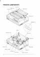
PRINTER COMPONENTS Entry,slot ver [ridge slot I ‘\ ... +-—___,. .
Component Description Paper guide Aligns single sheets (cut forms) to help the printer detect when paper is inserted. Release lever Releases pressure on the paper. This lever must be back for cut-sheet forms ( ~ ), and forward for fanfold forms ( ~ ). Front cover Protects the print head and other internal components of your printer. Mute cover Reduces the printing noise. Rear cover Protects the tractor feed unit and separates incoming and outgoing fanfold forms.
SUMMARY OF PRINTER FEATURES Feature Function Dot matrix (24-wire) impact printing High-Speed Draft, Draft and Letter-Quality printing. Extensive software support It is compatible with the Epson and IBM standard, and works with any software that supports those printers. AEC mode Auto Emulation Change (AEC) mode is provided to select theproperemulation mode automatically sent from your program.
Feature Function Character spacing Prints in 10, 12, 15, 17,20, and 24 CPI, as well as proportional spacing. LCD Control panel Button control for fonts, pitches, paper movement, and paper park functions. LCD messages indicate current status. Font/Pitch Lock Ignores font and pitch selections sent from your computer, and stays on the selected font and pitch with the control panel. Quiet mode Reduces printing noise by approximately 50%. However, printing speed is also reduced.
I FONT STYLE EXAMPLE The following example shows the many font styles your printer can print. RESIDENT: HS-Draf t Draft Roman S ans e r i f Cour i e r Fc- 1 z : FC-2Z : FC-3Z : FC-5Z : FC- 10Z : FC- 11 Z : FC-12Z : 6 Pres t i ge Scrip t Orator Orator-2 Letter Gothic Blippo Cinema OCR-B OCR-A CODE 39 , UPC/EAN I,,,):..:;.,.:,/,! ::,;::, ; ;.;::.:[!“”’’1!..:;1: ,:1. :11.”.,:.1!. :1(:1:‘t!, ‘];:3 ,.q, ::j;:,:/~ (;! Af~(::i.
Res i dent LQ fonts are : Roman characters , Courier characters, SCx.LPX. ch.a,qac...teti. Print Sanserif characters, P r.es ~ i g e c h a r a c t c rs , p i t ches P i ca pi t ch are : ( 10 C~PI) , Elite pitch (12 CPI) , pica pitch ([7 CPI), Semi-condensed Pitch (1‘5 CPI ) , Cond:nsed Lmdmsd:1ite pitch(20CPI), Condensed proportional. Normal proportional, Quad-s i z MI.
MEMO
chapter2 SETTING UP THE PRINTER This chapter describes the following procedures to set up your new printer. If you have optional accessories, refer to Chapter 7 after setting up the printer. . Printer placement . Unpacking the carton box . Mounting the platen knob ● Installing the ribbon cartridge . Configure your software for the printer PRINTER PLACEMENT Before you start setting up your printer, make sure that you have a suitable place on which to locate it. By “a suitable place”, we mean: .
I UNPACKING AND INSPECTION Now check each item in the box against Figure 2-1 to make sure that you have everything (there should be six items). If any of these items are missing, contact your supplier. FigureZ-l. Checkto makesure youhave allsixitems:1) Printer,2)Platen knob, 3) HlbbOn cartnage, 4j raper 5) Mute cover, and 6) User’s manual.
The optional accessories which you may have ordered with your printer are: ● Film ribbon cartridge (FZ24) . Font cartridges (FC series) . RAM cartridge (RC-32Z, DC-32Z) . Serial-Parallel converter (SPC-8K) . Automatic sheet feeder (SF- 10DS) ● Pull tractor unit (PT-1OZS) For details of the optional accessories, refer to Chapter 7.
I SETTING UP Place the printer in the desired location. and remove all packing material from the printer as shown in Figure 2-2. This packing material is intended to prevent damage to the printer while in transit. You will want 10keep all the packing material. along with the printer carton, in case you have to move the printer to a new location. Figure 2-2. Remove the packing material from the printer. Installing the platen knob The platen knob is packed into an accessory box with other accessories.
I Removing the front cover Open the front cover by 1ifting up the back cover using the two grips on either side. then remove the cover by pulling up (see Figure 2-4). -. FlgUre Z-4. (Jpen the hont cover, and remove It by pulllng up NOTE: You can keep the front cover installed on the printer, as shown in Figure 2-5. But, in this case you must take care not to injure your fingers with the tear assist edge. Tear assist cdsze .. Front e.. . . . Figure 2-5. The front cover can stay on the printer .
Installing the ribbon cartridge Now install the ribbon with the following procedure. 1. Take the slack out of the ribbon by turning the tension knob on the ribbon cartridge clockwise as shown by the arrow. 1 ension knob I Figure 2-6. Take out the slack of the ribbon by turning the tension knob on the ribbon cartridge. 2. Guide the ribbon between the print head and the silver print head shield, making certain that the spindles on the cartridge holder fit into the sockets on the cartridge itself.
3. Make sure that the ribbon is positioned between the print head and the print head shield as shown in Figure 2-8. 4. Take the slack out of the ribbon again by turning the tension knob. r Figure 2-8. Make sure that the ribbon is positioned correctly. Installing the front cover After you have installed the ribbon cartridge, re-install the front cover. 1. Insert the tabs into the slots on the printer case. 2. Swing down the rear of the front cover to close it. Figure 2-9. Installingthe frontcover.
I Installing the paper guide Follow the procedure below to install the paper guide: 1. Insert the two slots on either side of the paper guide into the two tabs on the rear cover. 2. Place the paper guide horizontally, as shown in Figure 2-10. Figure 2-70. Installing the paper guide horizontally. Installing the mute cover Follow the procedure below to install the mute cover: 1. Insert the tab on the Ieft side of the mute cover into the hole on the front cover. 2.
Connecting the interface cable Connect the printer to your computer using a standard Centronics parallel interface cable. On a PS/2 or PC/AT-type computer, this means that you use the25-pin D-type connector at thecomputerend, and the Amphenol-type 36pin connector at the printer end. The configuration of the printer’s connector is given in Chapter 11 should you need a cable for connecting to another computer. If you need to connect to a serial port, use the optional Serial-Parallel Corwerter, SPC-8K.
I Configuring your software for the printer Most application software programs let you specify the type of printer you are using so that the software can take full advantage of the printer’s features. Many of these software packages provide an installation or setup program that presents a list of printers. This printer is setup to emulate the Epson printer commands at the factory. If you want to emulate the IBM printer commands, you can select it with the Electronic DIP Switch (EDS) mode.
R chapter 3 PAPER INSTALLATION AND USE This chapter describes instructions for printing such as selecting paper types, iidjusting the printing gap, and installing paper. SELECTION OF PAPER Your printer accepts any of the following types of paper: ● ● ● ● Single sheets (cut forms) and stationary Use the friction feed or the optional Automatic Sheet Feeder. Fanfold forms Fanfold forms have holes along the sides and perforations between the sheets.
NOTES: 1. Never feed labels backward. Labels can easily peel off the backing and get stuck in the printer. To remove labels from the paper path after you finish printing, first tear off the labels at a point before the paper slot. 2. Use labels only under normal operating conditions. The labels are especially sensitive to temperature and humidity. 3. Do not leave labels loaded in the printer between jobs. They curl around the platen and may jam when you resume printing.
ADJUSTING THE PRINTING GAP The distance between the print head and the platen can be adjusted to accommodate different paper thicknesses. The adjustment lever is located at the left side of the printer. Pushing the adjustment lever towards the rear of the printer narrows the gap; pulling it towards the front of the printer widens the gap. There are five positions, and you can feel the lever clicking into each position.
LOADING FANFOLD FORMS This printer accepts fanfold forms up to 10” wide. This printer can feed fanfold forms either from the rear or from the bottom of the printer, as shown in Figure 3-3, Figure 3-3. Paper path for fanfold forms This section will take you through the procedures for loading, parking and unparking fanfold forms from the rear of the printer. If you want to feed paper from the bottom, you must use the optional Pull Tractor Unit, (Refer to Chapter 7.
Loading the paper 1. Place a stack of fanfold paper behind and below the printer. 2. Turn the printer’s power OFF. 3. Pull the release lever toward the front of the printer ( ~ ). This has the effect of releasing the paper from the platen roller, and engaging the tractor feed. 4 Open the mute cover on the front cover, as shown in Figure 3-4. , Release level Figure 3-4. Opening the mute cover and correct lever position. 5. Open the rear cover using the two grips on either side, as in Figure 3-5.
7. Open both tractor covers and mount the paper by aligning holes with the pins on the tractor unit. Tractor cover mamp’ever Figure 3-6. Mount the fanfold paper over the tractor units. Adjust the spacing of the tractor units by sliding them along the bar, using the clamp lever at the back of each unit to release and lock them in position. When the clamp lever is up, the unit is released, and when it is down, the unit is locked.
I 11.Turn on the power using the switch located at the front of the printer. The printer will beep, indicating that the paper is not yet fully loaded. A “PE>’ message will also flash on the LCD display to confirm this. Mute cover Figure 3-8. Close the rear cover and the mute cover, then set the paper guide horizontally 12.Now pull the bail lever toward the front of the printer. The paper will be fed and adjusted past the print head to a position ready for printing. er Figure 3-9.
Paper parking After loading fanfold paper with internal tractor unit, you do not have to unload it when you want to print on a cut sheet. The printer will “park” it for you if you follow the procedure below. 1. To begin paper parking, start with the power ON, fanfold paper loaded in printing position, and the release lever toward the front of the printer ( &). 2. Press the [ ON LINE ] button on the control panel to set the printer offline. The ON LINE indicator light will turn off. 3.
Paper unparking When you want to resume using fanfold paper, the procedure is as follows. 1. 2. 3. 4, Remove all cut forms from the printer. Mount the paper guide in the horizontal position. Move the release lever toward the front of the printer ( !& ). Move the bail lever forward. The printer will automatically feed the parked fanfold paper back into position for printing. NOTE: The printer beeps intermittently if you move the release lever while the paper is loaded.
LOADING SINGLE SHEETS This section will take you through the procedures for loading single sheets of paper. The paper path for cut forms is shown in Figure 3-11. Figure 3-11. Paper path for cut forms. If you are using the optional Automatic Sheet Feeder, refer to Chapter 7. Raise the paper guide in position on the rear cover of the printer. : lever Figure 3-12. Raise the paper guide for single sheets. 2. Adjust the paper guides to match the size of the paper you will be using.
3. Turn on the power using the switch located at the front of the printer. The printer will beep, indicating that there is no paper in position for printing. The “PE” message will also flash on the LCD display to confirm this. 4. Make sure that the release lever is at rear position ( m ). If fanfold paper is already mounted in the printer, press the [ EJECT/PARK ] button to park the paper in the off-line state, then move the release lever toward the rear of the printer. 5.
Figure 3-14. Pull the bail lever forward to load paper. 7. If you want to set the paper to a different position, set the printer off-line by pressing the I ON LINE Ibutton, then set the paper position by using the micro-feed function. (For details, refer to Chapter 4.) —.
chapter4 CONTROL PANEL OPERATIONS The control panel buttons can be pressed individually to perform the operations indicated by their names. Other functions can be achieved by holding these buttons down when you turn the printer’s power on, or by pressing the control panel buttons in combination. This chapter explains all the button and indicator functions.
ON LINE The ~ ON LINE ] button sets the printer on-line and off-line. The status changes each time you press the button. When the printer is on-line, it can receive and print data from the computer and will be indicated by the ONLINE indicator being lit. When the printer is off-line,.it stops printing and sends the computer a signal indicating that it cannot accept data. The printer powers up in the on-line status when paper is loaded.
EJECT/PARK NOTE: This button has no effect if the bottom feed mode is selected. This button results in different functions depending on the position of the release lever. If the release lever is facing toward the rear of the printer for the cut forms ( ~ ), pressing this button ejects the PaPer. If the release lever is facing toward the front of the printer for the fanfold forms ( ~ ), pressing this button parks the forms. PITCH This button allows you to select the printing pitch.
FONT This button selects the font to be printed. Draft font is selected at power-up unless the default settings are changed. To change the font, set the printer offline, then press the button repeatedly until the proper font is highlighted on the LCD display. The selections cycle in the following order: Font LCD Message Roman Sanserif Courier Prestige Script High-Speed Draft Draft Optional font [OPTION I NOTE: If the optional Font Cartridge isnot installed, the’’OPTION”message will not illuminate.
POWER-UP FUNCTIONS In addition to their normal functions, all of the control panel buttons perform “special” functions if you hold them down while switching the power button on. ~D~ [mode Do[ adjustment mode mm I I L-J ‘“c”‘J’’’’’:’KEAE’D’ONL n‘“NTn n mm —– A ,0s. 8,.. ,WITC” SET PRINT EXIT 1 1 I I I F(jnt Pitch Prin[ area Long lock lock test test Short test Figure 4-2.
Long test mode If the printer is turned on while the [ PAPER FEED I button is pressed, the printer will enter the long self-test mode, with the “P2” message on the LCD display. The printer will print the version number of the printer’s ROM, the current Electronic DIP Switch (EDS) settingsand the current Dot Adjustment setting, followed by the entire character set printed in each font and pitch available. The test repeats endlessly, so you must turn the power off to stop it. ... ,., ,.~.,, ----- .-.. ..
Print area test mode By holding the I EJECT/PARK/button down during power-up, theprinter will enter the print area test mode. You can find how many lines on your paper are available for printing with l/6-inch line feeding. The printer will show the “P3” message on the LCD display and print the first line message on the paper, then print the last line message after feeding to the bottom of the page. If you have loaded the fanfold paper, only the first line message is printed.
Dot adjustment mode This mode is used to adjust the vertical alignment of text and graphics on successive bi-directional passes. After a period of time, your printer may work itself out of alignment on left and right printing passes, appearing most visibly during graphics printing. This mode will probably be used very rarely. 1. Turn the printer off and then turn it on again while holding down the I EJECT/PARK I and I ON LINE / buttons.
5. To change the mode for which the bi-directional adjustment is performed, press the I ON LINE I button. This will cycle between “LQ”, “DRAFT”, “DRAFT COND” and “BIT IMAGE”.
Hexadecimal dump This feature is useful for programmers who are debugging printing programs and want to see the actual codes the printer is receiving, (Some computers change the codes the programmer intended.) In this mode, all data received will be printed in a hexadecimal dump format, rather than the control codes being acted on as command codes. This mode is accessed with the following procedure: 1. While holding both the I PAPERFEEDI and I EJECT/PARKIbuttons down, turn power ON.
SWITCH COMBINATION FUNCTIONS Several additional functions can be achieved by pressing the control panel buttons in combinations. Top of form m ~~ = POWER .“’cRO’””- ~ L----J ‘J’’T’’’:KpE;EEDyO 1 m -. ““” 71 n— .‘“NT Em. m.. SWITCH 1- Save macru 8 - —CCL–2 SE, ,,,!4, Form Buffer clear/All reset feed ‘x” I If you are using cut forms, this operation ejects the current page. If you are using fanfold forms, it feeds to the top of the next page. 1.
Forward micro-feed For fine alignment, you can feed the paper forward in very small increments as follows: 1. Press the I ON LINE ] button to set the printer off-line. 2. Press the [ ON LINE I button again and hold it down. 3. While holding the I ON LINE 1button down, press the I PAPERFEED] button. The paper will start advancing in a series of small steps. When you want to stop, release both buttons.
Clearing the buffer/All reset The printer stores received data in a large memory buffer. This creates a problem when you want to abandon a printingjob and restart: the printermtiy beholding more data in itsbufferthan it hasactuallyprinted.and this unprinted data must be cleared out before restarting. Turning power off is one way to clear the buffer, but there is another way: 1. Halt the printing program on the computer.
NOTE: You can store the following settings with this procedure. ● ● ● ● ● Current Font Current pitch Current auto-loading amount for cut forms Current auto-loading amount for fanfold forms Current auto-loading amount in ASF mode to be stored are controlled in Standard mode and IBM mode separately. For example, the data stored in the Standard mode are not effective in the IBM mode, and vice versa.
CONDITIONS INDICATED BY MESSAGES AND TONES This section helps you identify the messages and the meanings of the tones. Summary of display messages Following table shows the summary of the messages on the LCD display. Meaninm and action LCD Message ;ROMAN 1 ROMAN LQ font is selected. ;SANSERIF[ SANSERIF LQ font is selected. ;COURIER I COURIER LQ font is selected. ~pREsTIGE{ I ;scRlpT PRESTIGE LQ font is selected. ~Hs-DRAFT{ High-Speed Draft font is selected.
LCD Message — Meanings and action Displuysin the EDS mode. Indicates the current status of the displayed EDS hank and switch number. Press the 1 EJECTPARKI button to change the status. Quiet mode is selected. Press the I PAPERFEEDI button while in the on line mode to return to the Normal mode. Front panel setting are saved in the printer’s memory as a “MACRO”. Short print test mode is selected. Long print test mode is selected. Turn off the power switch to cancel the long print test mode.
Summary of beep tones Following table shows the summary of beep tones. Bee~ tones Meanings Two seconds tone Printer detects an error condition. Turn off the power switch and turn it on again. Long tone, once Printer detects an error condition. Turn off the power switch and turn it on again. Four short tone sequence, two times Printer is out of paper. Short tone. once ● ● ● ● ● Short tone.
48
1 chapter 5 DEFAULT SETTINGS-EDS MODE From the control panel you can change the parameters that define how your printer works. These parameters become your power-on settings. This function is called the Electronic DIP Switch (EDS) mode. HOW TO SET THE EDS MODE The EDS mode in this printer has 16functions that you can set as the poweron default. Turn the printer on while simultaneously holding the -, EEECHl,and EJECT/PARK I buttons. The “EDS” message will show on the LCD display.
FUNCTIONS OF THE EDS SETTINGS The printer stores the parameters that you can select from the control panel while in the EDS mode. A default is the setting that the printer will use if none is specifically selected by a program. When you first turn on or later reset your printer these default settings’will take effect. By changing the settings, you can alter various printer functions to match your specific requirements. The following will help you choose the proper settings.
Switch A-1: Emulation Select the mode compatible with your computer and software. In the Standard/Epson mode. the printer operates likethe Epson LQ-860/850. In the IBM mode, it operates like the IBM Proprinter X24E/24P, P, S/l The ON position selects Standard/Epson mode. The OFF position selects IBM mode. Switch A-2: Auto Emulation Change (AEC) Mode This switch selects the Auto Emulation Change (AEC) mode.
Switch B-2: Paper-out When this switch is OFF the printer ignores the paper-out detector and prints down to (and beyond) the bottom edge. Switch B-4: This switch is used for technical purpose only. Leave this switch ON. Switch B-5: Printable area This printer can use two types of printing area format for single sheets (cut forms).
I Switches C-3 to C-5: Page Length Leave these switches ON if you will be using 11-inchforms. You will need to change the switches if you will be using a different page length as shown below: Page Length 11 inches/Letter 8 inches 11.7 inches/A4 12 inches 8.5 inches/Letter 14 inches/Legal 10.5 inches/Executive 7.
International character sets differ in their assignment of 12 character codes in the Standard Italic character set. See the character tables in Chapter 11. With these switches you can select one of eight character sets as follows: D-2 D-3 ON ON OFF ON ON OFF OFF OFF Country U.S.A.
Optional fonts (marked with*) can be selected only when the corresponding font cartridge is installed in the printer. If the corresponding font cartridge is not installed, the Roman is selected. Switch F-1: EDS Setting If you set this switch OFF, the current EDS settings are all cleared, and restores the Factory Settings.
56
chapter 6 TROUBLESHOOTING This chapter helps you identify printer conditions and problems that you can often correct yourself. Remember that your printer is a highly sophisticated electronic device, which also contains high voltage inside. For that reason, only carry out those operations described in this chapter. CAUTION: Any attempt to carry out operations other than those described here may result in electric shock and/or damage to the printer.
● Printer test works, but printer does not print when attached to computer Probable Cause [ Action Printer cable has I Make sure that the printer cable is correctly connected at a problem. both ends, printer and computer. Problem with the application program. Refer to your application program manual. Incorrect emulation is selected. Select the other emulation with the EDS setting. See Chapter 5.
● Printer does not feed paper Probable Cause I Action Paperisjamming. Remove all forms and pieces of paper. Bailleveris closed Open the bail lever. Bail lever automatically closed when before paper goes the paper goes through the bail lever location. throughthe baillever location. Adjustment lever Check the setting of the adjustment lever. See “Adjusting is set incorrectly. the printing gap” in Chapter 3. Fanfold form is parked. ● Move bail lever forward to unpark the fanfold paper.
● Incorrect number of lines on a page Probable Cause Action Paper is adjusted Set the top of form. See “Top of form” in Chapter 4. incorrectly. Paper has shifted Readjust forms. backwards after several forms printed correctly. Incorrect emulation is selected. Select the other emulation with the EDS setting. See Chapter 5. Problem with the Refer to your application program manual. application program. Distance printer must pull paper is too far. Move paper closer to the printer.
● Characters are wrong or missing; formatting control codes do not work Probable Cause I Action Problem with the Refer to your application program manual. application program. Some wires are Printer needs repair. missing from the print head. Wrong default setting with EDS switches. Check the current EDS setting. Modify the EDS setting. s Dots are missing or print quality is poor Probable Cause I Action Adjustment lever Check the position of the adjustment lever. is set incorrectly. See Chapter 3.
● Printer is unstable; Wrong characters are printed; Left margin changes; printing stops Probable Cause I Action -1 Static electricity Increase the humidity. is resulting from Move devices with electric motors away from the printer. low humidity or interference from nearby electrical devices. ● Left margin moves to the right during printing Probable Cause I Action The print head is not moving correctly.” Check that the ribbon and paper are correctly installed.
● Printer case is hot to the touch Probable Cause Action Printer’s vents are blocked. Move object away from the air vents, including the bottom of the printer. ● . Printer is noisy Probable Cause ] Action I The printer vibrates. Move any objects that touch the printer. Ensure that the printer is on a level, study surface. Printer covers are open. Close covers.
MAINTENANCE Essentially, your printer is a robust piece of equipment, but should be treated with a modicum of care in order to avoid malfunctions. For example: ● ● ✎ ● ● 64 Keep your printer in a “comfortable” environment. Roughly speaking, if you are comfortable, then the environment is suitable for your printer (see Chapter 2). Do not subject the printer to physical shocks or excessive vibration. Avoid over-dusty environments. Dust is the enemy of all precision mechanical devices.
chapter 7 OPTIONAL ACCESSORIES You can select the following accessories as option. ● ● ● ✎ ✎ Automatic sheet feeder (SF- 10DS) Pull tractor unit (PT-1OZS) Font cartridges (FC series) RAM cartridge (RC-32Z, DC-32Z) Serial-Parallel Converter (SPC-8K) This chapter describes how to install and use these optional accessories. NOTE: When you install or remove the optional accessories, turn off the power switch.
Setting up The procedure to install the ASF is: 1. Use the printer’s EDS mode to select ASF as “installed”. (For details, please refer to Chapter 5.) 2. Open the front cover by lifting up the back using the two grips on either side, then remove the cover by pulling up. 3. Open the rear cover by lifting up the front using the two grips on either side. 4. Move the printer bail lever toward the front of the printer to open the paper bail. Figure 7-2. Remove the front cover, and open the rear cover, 5.
6. Lower the rear side of the Automatic Sheet Feeder and attach it to the holder shaft. 7. Install the printer cover provided with the Automatic Sheet Feeder. r Printer I Figure 7-4. Install the printer cover. 8. Insert the hopper attachment on top of the hopper support section as shown in Figure 7-5. Figure 7-5. Insert the hopper attachment 9. Insert the stacker attachment into the holder on the front part of the sheet feeder.
NOTE: Set the front cover aside carefully after they have been removed from the printer. Reverse the procedure described above when removing the Automatic Sheet Feeder. 1 I Figure 7-6. Insert the stacker attachment. Loading paper 1. If fanfold paper has already been loaded in the printer, park the paper through the rear slot. 2. Push the printer release lever toward the rear of the printer (~) to load single sheets. 3.
4. Adjust the left paper guide to the desired left position by moving it horizontally in either direction. Figure 7-8. Adjust the paper guides to accommodate the width of the paper. 5. Adjust the right paper guide to accommodate the width of the paper. The guides should be adjusted to restrict the amount of horizontal play while allowing the paper to slide up and down freely between the two paper guides. The ideal distance between paper ream and paper guides is 0.25 mm (0.
8. Push the paper loading lever toward the rear of the printer. m Figure 7-10. Push the paper loading lever to hold the paper stack. Now, you are ready to start printing with the Automatic Sheet Feeder. Feeding a single sheet A single sheet of paper can also be fed manually with the Automatic Sheet Feeder. 1. Set the paper by inserting into the slot at the front of the stacker attachment, as shown in Figure 7-11. Figure 7-11.
PULL TRACTOR UNIT (PT-IOZS) You can use the Pull Tractor Unit to print on fanfold forms or multi-part forms through the bottom feed slot. Setting up The procedure to mount the Pull Tractor Unit is: 1. Open the front cover by lifting up the back using the two grips on either side, then remove it. 2. Open the rear cover by lifting up the front using the two grips on either side. 3. Move the printer bail lever toward the front of the printer to open the paper bail. 4.
I Lock lever Figure 7-13. Install the Pull Tractor Unit onto the printer by pushing the lock levers. 6. Install the paper guide provided with the Pull Tractor Unit, as shown in Figure 7-14. 7. Install the printer cover provided with the Pull Tractor Unit. Printer co Figure 7-14. Mount the paper guide and the printer cover onto the printer. NOTE: Set the paper guide and front cover aside carefully after they have been removed from the printer.
Loading paper 1. Open the printer cover. 2. With the tractor covers open, guide the paper from the bottom of the printer, by a~igningholes with the pins on the tractor unit. Clamp lever / Tractor covel :1 Figure 7-15. Mount the fanfold paper from the bottom of the printer. 3. Adjust the spacing of the tractor units by sliding them along the bar, using the clanm, lever at the back of each unit to release and lock them in position.
Clamp lever I / Tractor cover # ,,— Figure 7-16. Close the tractor covers after adjust the spacing of the tractor umts by slung mem along me bar. 5. After setting upthe paper from the bottom of the printer, installthe printer cover. Printer :1 Figure 7-17. Mounf the printer cover. Now, 74 you are ready to start printing with the Pull Tractor Unit.
FONT CARTRIDGES AND RAM CARTRIDGES This printer has five built-in LQ fonts, and a 16 K-byte printing buffer. You can add the following optional fonts or expand the printing buffer by installing optional cartridges (Font Cartridge or RAM Cartridge).
To install or change a cartridge, follow the procedure below. 1. Turn off the power switch at the front of the printer, and open the front cover. 2. Remove the connector cover at the right side of the printer. Figure 7-18. Remove the connector cover at the right side of the printer. 3. Push out the cap from the connector cover, as shown in Figure 7-19. NOTE: Keep this cap in a safe place. I Figure 7-19. Push out the cap from the connector cover. 4. Install the connector cover into the printer.
5. Insert the cartridge into the.slot of the connector cover, and slide it all the way in. Figure 7-20. Insert the cartridge into the slot of the connector cover. b. Close the front cover. NOTE: Remount the cap on the connector cover if you are not using an optional cartridge.
I INTERFACE CONVERTER (SPC-8K) To run the printer in serial mode. you should use the optional Serial/Parallel Converter (SPC-8K). The procedure to install the Converter is: 1. Set the DIP switches on the SPC-8K before attaching it to the printer. (See next page for detailed information.) 7-. Turn off the power switch and disconnect the power cord from the power source. 3. Disconnect the interface cable if attached. 4. Connect the Parallel connector to the printer. 5.
DIP Switch Functions on The Converter It is necessary to make compatible the data transfer conditions between the computer and the serial interface board with the DIP switch settings on the converter. Following table shows the functions of the DIP switches on the SerialParallel Converter.
80
chapter 8 PRINTER CONTROL COMMANDS The printer has two emulation modes: Standard/Epson mode and IBM mode. In Standard/Epson mode. the printer emulates the functions of the Epson LQ860/850, and the graphics commands for NEC 24-wire printers. In IBM mode, the printer emulates the IBM Proprinter X24E/24P and PS/1 printer. Additional command codes are included as a superset of these emulations. The emulation is changed by means of EDS switch A-1. When it is ON.
FONT CONTROL COMMANDS Select print quality Mode ASCII Std. Decimal “X” Hexadecimal 27 120 17 n 1B 78 n “Changesthe print quality according to the value of n, as shown below: n Print quality o 1 Draft Letter quality Ignored if the FONT LOCK mode was selected during power-up.
n o 1 2 3 4 5 6 7 8 9 10 Font Font Roman Sanserif Courier Prestige Script OCR-B OCR-A Orator Orator 2 TW-Light Letter Gothic (FC-2Z) (FC-2Z) (FC- IZ) (FC-l Z) (FC-3Z) (FC-lZ) (FC-lZ) 11 Blippo (FC-3Z) 12 H-Gothic (FC-3Z) 13 Orane (FC- IZ) 14 Cinema (FC-2Z) 15 CODE 39 (FC-2Z) 16 UPC/EAN (FC-5Z) 17 Old Style (FC-5Z) 18 Firenze (FC-1 IZ) 32 SLQ Roman 33 SLQ TW-Li.ght (FC-12Z) (FC- 10Z) 34 SLQ Script Select italic characters Mode std.
Double-strike printing Mode Both ASCII “G” Decimal 27 Hexadecimal IB 71 47 Causes subsequent characters to be printed in double-strike mode with a slight vertical paper motion in between, causing a thickening ‘of horizontal strokes. For bold print, use of double-strike is recommended in LQ mode, and combined use of emphasized and double-strike is recommended in draft mode.
Select score Mode std. “(” <()> Hexadecimal Decimal ASCII <3> “-” )1/ <1> 27 40 0 112 45 1 /?/ 3 IB 28 2D 03 00 01 }1/ /12 /12 Start score according to the values of nl and n2, as shown below. /12 Function }?1 Function 0 Cancel score 1 Single continuous line 2 Double continuous line 5 Single broken line 6 Double broken line 1 Underlining 2 Strike-through 3 Overlining Select ornament character Mode std.
Subscript Mode Both ASCII Decimal “s’” <1> Causes subsequent characters 27 83 1 Hexadecimal IB 53 01 to be printed as subscripts. Does not change the character pitch. Cancel superscript or subscript Mode Both ASCII “T” Decimal 27 84 Hexadecimal IB 54 Stops printing superscripts or subscripts and returns to normal printing.
CHARACTER SET COMMANDS Select standard character set Mode ASCII Both “t” 27 116 0 IB 74 00 Std. “I” 28 0 Ic 49 0 Decimal 73 Hexadecimal Selects the standard character set. This is the power-up default in Standard mode if EDS switch D-1 is set to OFF. Select IBM character set Mode Both ASCII Std. Hexadecimal “t” <1> Decimal 27 116 1 IB 74 01 “I” 28 IC 49 <1> 73 1 01 Selects an IBM character set.
I Select international character set Mode Std. Hexadecimal Decimal ASCII ‘“R” /{ Selects an international 27 character 82 1B }1 set in the Standard 52 17 character set according to the value of r?. n Character set 0 I 2 3 4 5 6 7 U.S.A France Germany England Denmark I Sweden Italy Spain I n Character set 8 Japan 9 Norway 10 Denmark H 11 Spain 11 12 Latin America 13 Korea 14 Irish 64 Legal The first eight of these character sets (from U.S.A.
Enable printing of all character codes Mode Std. IBM ASCII 43> Decimal ‘1” ‘1” Hexadecimal nl n2 28 92 nl n2 IC nl n2 27 92 nl n2 10 5C nl n2 5C nl n2 Enables printing of all characters in the IBM character set, including those assigned to character codes which are normally considered control codes. This command remains in effect for the next id + n2 x 256 characters, where nl and n2 are numbers between Oand 255. During this interval no control functions are executed.
CHARACTER SIZE AND PITCH COMMANDS Pica pitch Mode Std. IBM ASCII “P” Decimal Hexadecimal 27 80 IB 50 18 12 In Standard mode, changes from either elite or semi-condensed to pica pitch (10 cpi) or from condensed elite to condensed pica (17 cpi). In IBM mode, changes from either elite or condensed to pica (10 cpi). Ignored if the PITCH LOCK mode was selected during power-up. Elite pitch Mode Std.
Cancel condensed printing Mode Both ASCII Decimal 18 Hexadecimal 12 In Standard mode, changes from condensed pica to normal pica or from condensed elite to normal elite. In IBM mode, always changes to normal pica. Ignored if the PITCH LOCK mode was selected during power-up. Proportional spacing Mode Std. IBM ASCII “p” “P” Hexadecimal IB 70 n IB 50 n Decimal 27 112 n 27 80 n n n Causes subsequent characters to be proportionally spaced wnen n is 1, and cancels it when n is O.
Select font and pitch Decimal Mode ASCII IBM “I” n 27 73 n Hexadecimal IB 49 n Changes theprint font and pitch accordingto the valuesof n, as shown below.
Select character width Mode Std. ASCII Decimal “E” n 28 69 n Hexadecimal IC 45 n Select a character width according to the value of n as shown below. n O 1 2 Character width Normal-wide Double-wide Triple-wide Select master print mode Mode Std. ASCII “!” Decimal n 27 33 n Hexadecimal IB 21 n Selects a combined print mode according to the value of n. The value of n is the sum of the values given below for the desired characteristics.
Select double or quadruple size Mode Std. ASCII “h” Decimal n 27 104 n Hexadecimal 16 68 n Selects the size of subsequent characters as shown below. Extrahigh characters align along the cap-line of normal characters, with ‘thebase line temporarily moving down. Line spacing is temporarily doubled when n = 1 and quadrupled when n =2. n Effect 0 Normal size 1 Double-high, double-wide 2 Quadruple-high, quadruple-wide Print double-height characters Mode Ascll Std.
Select character height, width, and line spacing Mode IBM “[” “@” <4> Hexadecimal Decimal ASCII n <0> 27 91 64 m o 4 0 Onm IB 5B 40 00 00 04 n 00 m Selects a combination of character height, width, and line spacing according to the value of n and m, as below. Does not move the base line.
VERTICAL POSITION Set line spacing to 1/8 inch Mode Both Decimal 27 48 ASCII “O” Hexadecimal IB 30 ‘Sets the distance the paper advances or reverses in subsequent line feeds to 1/8 inch. Set line spacing to 7/60 or 7/72 inch Mode Both Decimal 27 49 ASCII “1“ Hexadecimal IB 31 Sets the distance the paper advances or reverses in subsequent line feeds to 7/60 inch (standard mode) or 7/72 inch (IBM mode). Set line spacing to 1/6 inch Mode Std.
I Set base unitfor line spacing Mode IBM <0> Hexadecimal Decimal ASCII “[” <4> ‘\” )1/ <0> 27 91 92 n2 o 0 n/ 4 0 /12 IB 5B 5C 00 00 04 n/ 00 n2 Sets the base unit for the line spacing commands, “3” and “J”, according to the values of nl and n2 as shown below. If other values specified, this command is ignored. This command becomes effective only after “3” or “J” is received, The default base unit is set to 1/216”.
Execute &SC> “A” Mode IBM ASCII “2” Hexadecimal Decimal 27 50 IB 32 Sets the line spacing to the value defined by the last preceding “A” command. Sets the line spacing to 1/6inch if there is no preceding “A” command. Line feed Mode Both ASCII Hexadecimal OA Decimal 10 Prints the current line and feeds the paper to the next line. See the preceding commands for the line spacing. Reverse linefeed Mode Std.
Perform one n/180-inch, n/216-inch, or n/360-inch line feed Mode Both ASCII ‘J.. Decimal 27 74 n ~ Hexadecimal IB 4A n Feeds the paper once by n/180 inches,n/216 inches, or n/360 inches, according to the defined base unit. The value of n is between 1 and 255. Does not move the print position right or left in the standard mode. Does not change the line-spacing setting. Perform one nl180-inch reverse line feed Mode Std.
Set page length to n lines Mode Both ASCII “C” Decimal 27 67 /1 Hexadecimal n IB 43 n Sets the page length ton lines in the current line spacing, where n is between 1 and 127. ‘Changing the line spacing later does not alter the physical page length. The current line becomes the top of the page.
Form feed Mode Both ASCII Decimal 12 Hexadecimal Oc Feeds the paper to the top of the next page according to the current page length, and moves the print position to the left margin. When the automatic sheet feeder (ASF) is selected with EDS switch A-5, this command ejects the current page. Return to top of current page Mode Std.
Set vertical tab stops node ] ASCII I “B” Both fl~ Ill I Decimal 27 66 nl Hexadecimal IB 112 42 nl 0 I n2 00 Cancels all current vertical tab stops and sets new vertical tab stops at lines nl, n2, etc., where nl, n2, etc. are numbers between 1 and 255. A maximum of 16 vertical tab stops can be set. The tab stops must be specified in ascending order; any violation of ascending order terminates the tab stop list. Standard termination is by the <0> control code.
Vertical tab Mode Both ASCII Decimal 11 Hexadecimal OB Feeds the paper to the next vertical tab stop and moves the print position to the left margin. Performs a line feed if no vertical tabs are set, as at power-up. Feeds to the top of the next page if vertical tabs are set but the current line is at or below the last vertical tab stop.
HORIZONTAL POSITION COMMANDS Set left margin Mode Std. ASCII “1” n Decimal 27 108 n Hexadecimal IB 6C n ‘Sets the left margin at column n (where n is between Oand 255) in the current character pitch (pica pitch if proportional spacing is selected). The left margin does not move if the character pitch is changed later.
Set left and right margins Mode I ASCII IBM “X” I nl n2 Decimal 27 88 nl I n2 Hexadecimal 58 nl n2 ] 10 Sets the left margin at column nl and the right margin at column n2. See the preceding commands for margin restrictions and other notes. Carriage return Mode Both ASCII Decimal 13 Hexadecimal I OD Prints the current line and returns the next print position to the left margin. If EDS switch A-4 is set to OFF, also performs a line feed.
Left just$y Mode Std. Decimal 27 97 0 ASCII “a” <0> Hexadecimal IB 61 00 Aligns subsequent text with the left margin, leaving the right margin ragged. Center text Mode Std. Decimal 27 97 1 ASCII “a” <1> Hexadecimal IB 61 01 Centers subsequent text between the left and right margins. Right justify Mode Std. Decimal 27 97 2 ASCII “a” <2> Hexadecimal IB 61 02 Aligns subsequent text with the right margin, leaving the left margin ragged. Full justify Mode Std.
1Set horizontal tab stop every n columns Mode std. ASCII “e” <0> Decimal // 27 101 0 Hexadecimal )1 IB 65 00 r? Cancels all current horizontal tab stops and sets new tab stops every n columns, where n is between 1 and 127. Reset all tab stops Decimal 27 82 Mode I ASCII I IBM ‘“R” Hexadecimal IB 1 52 Resets the horizontal tab stops to their power-up values in which a tab stop is set every 8 column starting at column 9. Also clears all vertical tab stops.
Relative horizontal tab in inches Mode ~IBM ASCII ‘cd” Decimal n] n2 27 100 nl Hexadecimal n2 IB 64 nl n2 Sets the next print position to (n] + n2 x 256)/120 inches from the current position. Ignored if this position is beyond the right margin. Absolute horizontal tab in inches Mode Std. ASCII “$” nl 112 Decimal 27 36 nl Hexadecimal n2 IB 24 nl n2 Sets the next print position to (n]+ n2 x 256)/60 inches from the left margin on the current line.
GRAPHICS COMMANDS Print normal-density 8-bit graphics Mode Both ASCII “K’” Decimal nl 27 75 n] n2 ml tn2 ,.. )12 t??] Hexadecimal t?12 IB 4B /?/ ml )72 n?2 .,, Prints bit-image graphics at 60 dots per inch horizontally. The graphic image is 8 dots high and n] + t12x 256 dots wide. Maximum width is 8 inches (480 dots). ml, n?2, ...
Print quadruple-density 8-bit graphics IMode I Both ASCII “Z” I n1 1’/2 Decimal m2 ml I 27 90 ~~1/~2 ml t?12 Hexadecimal 1B 5A n/ .,. ml I /72 m2 Prints bit-image graphics at 240 dots per inch horizontally (maxi‘mum 1920 dots wide), skipping every second dot in the horizontal direction. See “K” for other information. Print hex-density 24-bit graphics IModel Ll Std.
Select graphics mode Mode Std. Hexadecimal Decimal ASCII “*” M n2 27 42 n] n2 m2 ml ml no 1B 2A /?0 n] nl n2 ml m2 rn2 .,, Selects one of eleven graphics modes depending on the value of nO and prints bit-image graphics in this mode. See “K” (for 8bit graphics) or “Z” (for 24-bit graphics) for information on III, n2, ml, m2, . . no Graphics mode O 1 2 3 4 6 32 33 ~g 39 40 X-bitNormal-density 8-bit Double-density 8-bit Double-density.
Convert graphics density Mode I ASCII cESC> “?” Std. n m Decimal 27 63 n Hexadecimal m IB 3F n m Converts graphics defined by subsequent “K”, “L”, “Y” or “Z” commands to a density mode defined by “*”. n is “K”, “L”, “Y“ or “Z”, indicating the mode to be converted. m is a code from to <4> or <6> indicating one of the modes of “*”.
DOWNLOAD CHARACTER COMMANDS Define download characters Mode std. ASCII “’&” <0> /1I ,,~ nil ml dl u Decimal Hexadecimal IB 26 00 n/ 27 38 0 /?/ d n12 d.! mo dl n7/ d2 nd ,.. [!.1” n2 mo cl] tnl (I2 nd (1.1” Defines one or more new characters and stores them in RAM for later use. EDS switch A-3 must be set OFF: otherwise RAM is used as an input buffer, not downloading characters, and this command is ignored.
Define download characters Mode Decimal ASCII “=” /1.? IBM ,,~ )?/ /1’/ <()> ~t~ ml (11 27 17S ,,, d2 “#” 61 /t/ n?/ rd d.1’ 35 o /L5 f?.] M m9 Hexadecimal n2 /?.7 }?4 00 ns .,, ?n9 (/1 (I2 IB 3D )?/ /12 23 d.1” ml rd [11 d2 m9 d.1” Defines new characters and stores them in RAM for later use. EDS switch A-3 must be set OFF; otherwise RAM is used as an input buffer, not downloading characters, and this command is ignored.
nz5through n?9are compression mask bits. Data compression allows the efficient use of memory in storing downloaded characters providing space for more characters than would be available without compression. The printer repeats the previous dot column in the current column when the current column compression mask bit is set to 1. It is necessary to define all of Index Table data before the Dot Pattern data to download many characters. dl, d2, ... d.~is the Dot Pattern data being downloaded.
Select download character set Mode Std. ASCII “7o” <1> Decimal 27 37 1 Hexadecimal IB 25 01 Selects the download character set. Ignored when EDS switch A-3 is set ON. Shift download character area Mode Std. ASCII “t” “I” <2> Decimal 27 116 2 IB <2> 28 IC 49 02 73 2 Hexadecimal 74 02 Shifts the download character area defined between 0 to 127 to the area between 128 to 255. Select ROM character set Mode Std.
OTHER PRINTER COMMANDS Set h4SB to 1 Mode Std. ASCII “>” Decimal 27 62 Hexadecimal IB 3E the most significant bit of each subsequent byte received to 1, allowing users with a 7-bit interface to access characters with ASCII codes greater than 127. Sets Set MSB to O Mode Std. ASCII ‘s=” Decimal 27 61 Hexadecimal IB 3D Sets the most significant bit of each subsequent byte received to O. Accept MSB as is Mode Std.
Set printer off-line Mode std. IBM ASCII Decimal ‘“Q” II Hexadecimal 19 13 27 81 H IB 51 11 Sets the printer off-line. The printer disregards all subsequent ‘charactersand commands except ,which returns it to the online. The printer’s ON LINE indicator does not go off. In the IBM mode, the value of n should be 36, 81, or 180.
Uni-directional printing Mode Both ASCII “u” <1> Decimal 27 85 1 Hexadecimal IB 55 01 Causes subsequent printing to be done uni-directionally, ensuring maximum vertical alignment precision. One-line uni-directional printing Mode Std. ASCII “<” Hexadecimal IB 3C Decimal 27 60 Immediately returns the print head to the left margin, then prints the remainder of the line from left to right. Normal printing resumes on the next line.
Set print start position on ASF Mode Both ASCII “T” Decimal 27 25 84 n /? Hexadecimal IB 19 54 n Skips n/6 inches at the top of the page, where n is equal to or greater than 1. Ignored if EDS switch A-5 is ON. Reset printer Mode Both Std. ASCII “@” “@” Hexadecimal Decimal 27 64 IB 40 28 IC 40 64 Reinitializes the printer. Clears the print buffer and returns settings to their power-up values. Does not clear the input buffer or change ASF selections.
chapter 9 DOWNLOAD CHARACTERS With this printer you can create new characters and symbols, download their dot data. and have them printed in place of selected characters in the regular character set. Characters that can be generated in this way range from simple but useful symbols like the check mark through to complex Chinese or Japanese characters. Regular characters are permanently stored in the printer’s ROM, but characters you design are downloaded and stored in RAM for use.
● The minimum width of a character is five dots. ● Dots cannot overlap. ● You may define any position in the ASCII table. Photocopy the grid in Figure 9-1 to help design your new characters. We will use a tiny representation of a telephone symbol for our example. Figure 9-1. Use this grid (or one similar to it) to define your own characters. Assigning the character data Now, we calculate the vertical numerical values of the columns of dots, and enter them underneath the grid.
1 2 3 4 5 6 7 8 9 101112131415161718192021 22232425262728293031 128 64 32 16 8 4 2 1 128 64 32 16 8 4 2 1 128 64 32 16 8 4 2 1 ASCllCode: 60 Leftspace: Characterwidth 3/ Rightspace. 2 Figure 9-2. Telephone symbol wtth normal LQplca. Assigning a value of character space Besides being able to specify the actual width of the character, this printer allows you to specify the position in the standard grid where the character will print.
When defining characters, the number of printed columns (m1). and the sum of side spaces and the character width (mo + m1 + M) cannot exceed the value shown below’. Character mode Draft characters LQ pica characters LQ elite characters LQ semi-condesed I LQ proportional Draft super/subscript LQ super/subscript LQ prop. super/subscript L t?? 1 M + tn1+ m2 9 31 27 19 37 7 19 37 12 36 30 24 42 12 36 42 Sample program To demonstrate how to use the download characters.
1340 1350 1360 1370 1380 1390 1400 1410 1420 1430 1,440 1450 1460 1470 1480 1490 1500 1510 1520 1530 2000 2010 2020 2030 2040 2050 2060 2070 2080 2090 2100 2110 2120 2130 2140 2150 2160 2170 2180 :LPRINT CHR$(60); FOR 1=0 TO 347 STEP 25 LPRINT LPRI?fT CHR$(9); :LPRINT CHR$(61) ; FOR 1=0 TO 493 STEP 25 LPRINT LPRINT CHR$(9); U+-U; SCALE$=”+-+–H :LPRINT SCALE$; FOR 1=2 TO 8 LPRINT ‘+-+” LPRINT CHR$(9); ”0 ‘: FOR 1=1 TO 8 LPRINT u “;1; NEXT I LPRINT CHR$(27) ;’’%U;CHR$(0) LPRINT CHR$(27); ”M”; LPRINT CHR$(27)
DEFINING YOUR OWN CHARACTERS WITH IBM MODE Downloading fonts in IBM mode requires downloading character Dot Pattern data and character Index Table data. Dot pattern data controls which pins fire when printing a character. Index Table data is placed in a “lookup table” that provides information on where Dot Pattern data is stored in memory and defines certain attributes of the character. Assigning the download character set You can define one or more download character sets for later use in IBM mode.
Assigning the character dot pattern We will use a tiny representation of a telephone symbol for our example. 1 2 3 4 5 6 7 6 91011 1213141516171619202122232425262726293031 128 64 — — — ~ I I ~ ~ ~ ~a,I 32333435 I II I-I I I II II l-r I I Il-r I Ii I I-I I I-I I I 1I 1I ~ I I- 32 — — — 16 — — — 8——— 4 2 —— — 1 128 . . 1 04 I ~ ! ● ● ● ● ii 32 16 6 4 2 1 128 64 32 16 8 4 2 1 figure 9-3.
1 2 3 4 5 6 7 8 9101112131415161718192021 64 16 8-—. “r- Figure 9-4. ] j.T*’. I 4 2 1b 128 64 32 -–16 8 -- + 4 2 : : ,B 1$+ 22232425262728293031 ●10100.00,00 1.~ -j 32333435 ~ ,,,, -1 .——.. ..—. . ‘“ ! .. ! .— 1.1 ●IOIO!OI.’ .1 .1.1.~.l. —.— . . . ..— .. — .. — Fill up the adjacent dot, then write the “compression data” After you have written the “compression mask bit” data, line up all the character data for the “compression mask bit” that requires 6’0”.
Now we will calculate the vertical numerical values of the columns of dots, and enter them underneath the grid. Each vertical column is first divided into three groups of eight dots. Each group of eight dots is represented by one byte. which consists of eight bits. This is where the numbers down the left side of the grid come in. Notice that there is a number for each row of dots and that each number is twice the number below it.
The remaining five bytes (m5 through m9) indicate the compression mask bits. Each bits shows the data that will translate the compressed dot pattern data back to the original character pattern. For example, the compression mask bits of our telephone symbol are 011000000000010011110010 0000000001100000. So these bytes are 96, 4,242,0, and 96. You must define the index table data for all characters from Oto 255. If you do not want to define a particular character, enter Ointo that index table data.
1410 1420 1430 1440 1450 1460 1470 1480 1490 1500 1,510 1520 1530 1540 1550 1560 1570 1580 1590 1600 2000 2010 2020 2030 2040 2050 2060 2070 2080 2090 2100 2110 2120 2130 2140 2150 2160 2170 LPRINT CHR$ (27) ; “I” :CHR$(6) : FOR 1=0 TO 347 STEP 25 :LPRINT CHR$(60); :NEXT I LPRINT LPRINT CHR$(9): FOR 1=0 TO 493 STEP 25 :LPRINT CHR$(61): :NEXT I LPRINT CHR$(2’ ); ’’I’’ ;CHR$(2) ; “+-” ; LPRINT CHR$(9 ScALE$=”+–+-u :NEXT I :LPRItiT SCALE$; FOR 1=0 TO 2 LPRINT ‘+-+” ;“0 “; LPRINT CHR$(9 FOR 1=1 TO 8 LPRINT “ “
132
chapter 10 MS-DOS AND YOUR PRINTER When using your printer with an IBM PS/2, PC-AT or compatible, you will probably be using PC-DOS or MS-DOSas an operating system. A number of software tricks may be useful here. This chapter is not, however, a substitute for the operating system manuals supplied with your computer. To learn how to print files, etc. it is best to read the relevant parts of these manuals. PROGRAMMING THE PRINTER WITH DOS COMMANDS If your system includes the file PRINT.
I See your DOS manual for further information about the PRINT command. If your system does not include PRINT.COM, you can print files by using the PRN device name in COPY or TYPE commands such as the following: A>COPY README.DOC PRN A>TYPE README. DOC >PRN COPY qndTYPE do not permit you to execute other commands while the file is printing. If you want a particular font, or print pitch, you can make these settings frolm the control panel before you start printing. See Chapter 4.
A>EDLIN LQELITE.DAT --——New file ‘2:*-C %E — ‘V indicates that the following character is a control code. *V[ enters the code. has character code 27, and “[” is the 27th character from A in the ASCII sequence. Similarly, ‘VA enters the control code< 1>. See your DOS manual if you need further information about EDLIN. You can now set up the printer by sending it the file LQELITE.DAT.
PROGRAMMING WITH BASIC As an example of programming the printer on Microsoft BASIC. we have listed the program for the IBM-PC. This program runs in the printer’s Standard mode. and the downloadable condition. 1000 1010 1020 I 030 1040 1050 1060 1070 1080 1090 1100 1110 I 120 1130 1140 I i 5 i) I I (>() 1 I 70 1180 I I 9() 1] (]() ]~lo I ~zl) ~~30 1~~o 1250 1260 ] ~70 1280 1~ y [) 13100 1310 1320 I 3 3() 1340 1350 I 360 1370 1380 I 390 14 c o I 4 I () [ ~~o 1430 1440 I 4.
1580 I 590 1600 1610 1620 1630 1640 1650 1660 1670 1680 1690 1700 1710 1720 1730 1740 1750 1760 1770 1780 1790 1800 1810 1820 1830 1840 1850 1860 1870 1880 1890 1900 1910 1920 1930 1940 1950 1960 1970 1980 1990 2000 201’0 2020 2030 2040 2050 2060 2070 2080 2090 2100 2500 2510 2520 2530 2540 2550 2560 2570 2580 2590 2600 2610 2620 LPRINT H$; E$; ’’q’’ ;CHR$(l );’’ OUTLINED ’’; E$; ’’q’’ ;CHR$ (0);”, “: LPRINT E$; “q” ;CHR$ (2) ;“SHADOWED’’;E$; ’’; CHR $(0)(O) ;“, “; LPRINT E$; ’’q’’ ;CHR$(3) ;UOUTLINED WITH
2630 2640 2650 2660 2670 2680 2690 2700 2710 2720 2730 2740 2750 2760 3000 3010 3020 3030 3040 3050 3060 3070 3080 3090 3100 3110 3120 3130 3140 3150 3160 3170 3180 3190 3200 3210 3220 3230 3240 3250 3260 3270 3280 3290 3300 3310 3320 3330 3340 3350 3360 3370 3380 3390 3400 3410 3420 3430 3440 3450 3460 3470 3480 3490 3500 3510 138 RETURN ‘ Define LQ pica download character LPRINT C$; LPRINT E$; ”&’’ ;CHR$(0) ;CHR$(60) ;CHR$(60); RESTORE 3070 READ LS :LPRINT CHR$(LS); READ CW :LPRINT CHR$(CW): READ RS :LP
3520 3530 3540 3550 3560 3570 3580 3590 3600 3610 3620 363o 3640 3650 3660 3670 3680 3690 3700 3710 3720 3730 3740 3750 3760 3770 3780 3790 3800 3810 3820 3830 3840 3850 3860 3870 3880 3890 3900 3910 3920 3930 3940 3950 3960 3970 3980 3990 4000 4010 4020 4030 4040 4050 4060 4070 4080 4090 4100 4110 4120 4130 4140 4150 4160 4170 3,135,255, 7. 0, 63, 15, 0, 0. 15, 0, 0 1,255,240, DATA 0, 31, 0, 0 0, 31, 0. 0. 31, 0, 0, 31, 0, DATA 31, 0, 0, 31,128, 0 0, 31, 0, 0, 31.
4180 4190 4200 4210 4220 4230 4240 4250 4260 4270 4280 4290 4300 4310 4320 4330 4340 4350 4360 4370 4380 4390 4400 4410 4420 4430 4440 4450 4460 4470 4480 4490 4500 4510 452o 4530 4540 4550 4560 4570 4580 4590 4600 4610 4620 4630 4640 140 DATA DATA DATA DATA DATA DATA DATA DATA DATA DATA DATA DATA DATA DATA DATA DATA DATA DATA DATA DATA DATA DATA DATA DATA DATA DATA DATA DATA DATA DATA DATA DATA DATA DATA DATA DATA DATA DATA DATA DATA DATA DATA DATA DATA DATA DATA DATA o,]~o.
How the program works This program begins by assigning a number of printer commands to BASIC string variables (lines 1000to 1060).You can find most of these commands near the beginning of chapter 8. TheWIDTH “LPT1 :“ 255 statement in line 1080 means infinite line width. It prevents the IBM-PC from inserting unwanted carriage returns and line feeds in graphics data. Actual printing begins in line 1090.
142
chapter 11 . REFERENCE SPECIFICATIONS Printing system ..............................Serial ImpactDot-matrix Printing speed ................................Pica 210 Cps High-Speed Draft 160 CPS Draft 53 Cps Letter Quality Elite — 192 CPS 64 CPS Semi-condensed — 240 CPS 80 CPS Print direction ................................Bi-directional, logic-seeking Uni-directional, logic-seeking (selectable) Print head .......................................24 pins Life: 200 million dots Line spacing ..............
Characters ..................................ASCII International IBM special IBM block graphic IBM code page Download 96 16 sets (*) 111 50 6 sets (**) 255 * USA, France, Germany, England, Denmark I, Sweden, Italy, Spain I, Japan, Norway, Denmark II, Spain II, Latin America, Korea, Irish, Legal ** #437 (USA), #850 (Multi-Lingual), #860 (Portuguese), #861 (Icelandic), #863 (Canadian French), #865 (Nordic) Number of columns ...................CPI Pica 10 Elite 12 Semi-condensed 15 Condensed pica 17.
24-pin normal 24-pin double 24-pin CRT III 24-pin Triple 24-pin Hex * 60 120 90 180 360 24 24 24 24 24 X X X X X 480 960 720 1440 2880 * It is impossible to print adjacent dots in the mode marked with an asterisk (*). Paper feed ..................................Friction or push tractor feed (standard) Bottom feed with pull tractor (option) Paper feed speed ........................3.4 incheslsecond max Paper specifications Cut sheet Width ..............................7.2” - 11.0” (182.0 -279.
Emulations .................................Standard mode: Epson LQ-860/850, NEC 24-wire Graphics commands IBM mode: IBM Proprinter X24E, Proprinter 24P, PS/1 printer Interface .....................................Centronics parallel (standard) RS-232C serial (option) ‘ Ribbon type ...............................On-carriage, dedicated Fabric ribbon (Black only) Film ribbon (Black only) Ribbon life Film ribbon (FZ24) .............0.2 million characters (LQ pica) Fabric ribbon (Z24) .............
PINOUT OF INTERFACE CONNECTOR The following describes the pinout of,the interface connector (signals which are low when active are overlined). Parallel interface Pin Name 1 STROBE 2 3 4 5 6 7 8 9 10 11 DATA() DATA1 DATA2 DATA3 DATA4 DATA5 DATA6 DATA7 ACK BUSY 12 PAPER 13 SELECT N/C 14, 15 16 SIGNAL GND 17 CHASSIS +5V 18 19-30 GND RESET 31 32 ERROR 33 34,35 36 EXT GND N/C SELECT IN Function Goes from high to low (for= 0.
Serial Interface Pin Name 1 GND TXD 2 3 Function Printer’s chassis ground. This pin carries data from the printer. This pin carries data to the printer. This pin is always set space. This pin is Space when the computer is ready to send data. This printer does not check this pin. 4 RXD RTS 5 CTS 6 N/C GND N/C Signal ground. 11 RCH This printer turn this pin Space when it is ready to receive data. This line carries the same signal aspin 20. 12 Signal ground.
The following tables show the standard and IBM character sets. The decimal character code of each characters shown in an inset to the lower right of the character. The hexadecimal code can be found by reading the entires at the top and left edges of the table. For example, the character “A” is in column 4 and row 1, so its hexadecimal character code is 41. This is equivalent (4x 16+ 1 = 65) to decimal 65, the number in the inset.
I Standard character set #2 150
151
International character sets When an internationalcharacter set is selected by a command from software, the following changes are made in the Standard Italic character set: 35 U.S.A.
IBM character set #2 Code Page #437 (U. S.A.
154
I Code Page #850 (Multi-1ingual) Other characters are identical to Code Page #437.
Code Page #860 (Portuguese) Other characters are identical to Code Page #437.
Code Page #861 (Icelandic) Other characters are identical to Code Page #437.
Code Page #863 (Canadian French) Other characters are identical to Code Page #437.
Code Page #865 (Nordic) Other characters are identical to Code Page #437.
Character set #1 Other characters are identical to character set #2. The duplication of control codes enables systems with a 7-bit interface to obtain control functions when the most significantbit is set to 1by the “>” command in the standard mode. o o 8 (NW o liii 1 (NUL) ~ b (oCl) 1 I-1 m, 4 (rE2) I-F r2 (OIX) IT I-3 (OC4) b m 5 I-T 2 3 I-I> (SYN) b b 6 7 8 9 A B c D E (BED b (CAN) b I--8 I-7 (8s) (HT) (EIII) IY5 b (LF) I-rO I-i (VT) (ESC) 1 F IIY (FS) (FF) 8.
a w) .
PROPORTIONAL SPACING TABLE This table lists the widths of your printer’s proportional characters, for Standard mode and IBM mode. The values giken are in 360ths of an inch. For example, a value of 36 is 36/ 360ths of an inch. You may need to enter these widths into a special table for your processing program so it can calculate the number of proportional characters that will fit on a line.
Character code Std.
Character code Std.
I Character Std.
Character code #861 #863 #865 #437 #850 #860 110 110 110 110 110 110 110 Chr. std.
Character code Chr. Std.
Character code Chr. Std.
Character code Chr. ,Std.
Character code Chr. ,Std.
Std. INT — INT INT — — INT Character code Chr. #437 #850 #860 #861 #863 #865 - 181 182 183 184 198 199 - 207 208 209 210 211 212 213 — 214 — 215 216 221 222 - 224 226 227 — 228 — 229 — — INT — — — 231 232 233 234 235 236 237 132 142 152 175 146 148 145 168 149 160 153 - 134 143 145 132 142 137 146 139 -“ 152 159 140 169 148 164 140 139 165 166 - 153 150 157 - 149 “141 167 158 157 152 151 - - A A A ~, s A H a H E E & 1 f t x ; 1 d c1 b ~ 0 p ]? ir 0 cl y ir Proportionalwidth IBM Norm.
( haracter code Chr. Std. #437 #850 #860 #861 #863 #865 238 167 161 INT - 239 ‘ 240 .242 .
INDEX A Absolutehorizontaltab, 108 Adjustmentlever,3, 21 AEC mode, 4, 51 All reset,43 Applicationsoftware,18 ASFcontrolcommands,119-120 Autoemulationchangemode,4, 51 AutoLine Feed, 5 [, 105 Auto loading position, 42 Automatic Sheet Feeder, 11, 51, 65 ,.. .
Double-height characters, 94 Doub]e-size characters, 94 Double-strike printing, 84 Download, 51 Download character commands, I I3-116 Download character set. 126 Download characters. 121-131, 144 Draft, 1. 143 E EDS mode, 5, 18,49, 50 EDS setting, 55 EJECT/PARK button, 33 Electronic DIP Switch mode, 5, 18.49. 50 Elite pitch, 90 Emphasized printing, 83 Emulation, 18, 51.146 Entry slot. 3 Expanded printing. 92 F Factory settings, 49 Fanfold forms, 1, 19, 145 Fanfold forms, loading, Z-27 Fanfold forms.
L Lables, 1, 19 LCD, 1, 5 Left justify. 106 Left margin, 104, 105 Letter Quality, 143 Line feed, 98 Line spacing, 95, 96.97, 143 Loading fanfold forms, 22-27, 73 Loading single sheets, 28-30,68 Locating the printer. 9 Long test mode, 36 LQ, 143 M Macro definition, 43 Maintenance, 64 Master print mode, 93 Most significant bit, 117 MS-DOS, 133 MSB. 117 Multi-part forms, 1, 5, 19 Mute cover.
I Quiet mode, 5,32 ~—–– [-E?– RAM Cartridge, 11,75 RAM usage, 51 Rear cover, 3, 23 Relative horizontal tab, 107, 108 Release lever, 3, 23 Reset all tab stops, 107 Reset printer, 120 Reverse feed, 98 Reverse line feed, 98 Reverse micro-feed, 42 Ribbon cartridge, 3, 5, 14, 146 Right justify, 106 Right margin, 104, 105 sSample program, 124-125, 130-131, 136-140 Score, 85 Selection of paper, 19-20 Self-test, 35, 36 Semi-condensed, 90 Serial-Parallel Converter, 11,78 Setting up, 12-I8 Shift download character
I COMMAND SUMMARY Standard Mode The following commands take effect with the Standard mode.
CONTROL CODE <[xx> “’>” ‘“’!” )1 /71 “@’” “’A” )/ ‘“B” /1/ /12 <()> “c-’ <()> /;””’ FUNCTION PAGE 117 Set NISB to I [ f? Conwxt graphics density I Z() Reset printer 97 Se[ line spwing to JI/60 inch 102 Set t c!-ticiil [ah stops 100 Sef pit “C” ~1 100” Set page length t[~II lines 106 Se[ h(~riznntal tab s[~,ps “D” 11/ 112 ..,. <()> “E” X3 Enlphasi~ect printing X3 <[IX-> C:mcel enlph:lsi/ed prin[ing ., ...
CONTROL CODE ..r. .. , I .. .R. ~ - ..”. ~ ..V..
I IBM Mode The following commands take effect with the IBM mode.
FUNCTION CONTROL CODE “S” “T” “U” I “W” n “x” nl ?12 “Y” nl n2 ml “z” 111n2 ml ‘$“ [ ..@” <4> “[” “ [“ “1” “K” Selectinitialconditions “[“ “T” <4> <0> nl n2 “[” “\” “ “ “d” .6;.. g..
I Consumer Response Star Micronics Co., Ltd. invites your suggestions and comments on your printer and this manual. Please address your correspondence to: WorldwideHeadquarters: STAR MICRONICS CO., LTD. 20-10 Nakayoshida Shizuoka, JAPAN 422-91 Attn: Product Manager AmericanMarket: STAR MICRONICS AMERICA, INC. 420 Lexington Avenue, Suite 2702-25 New York, NY 10170 Attn: Product Manager EuropeanMarket: STAR MICRONICS DEUTSCHLAND GMBH Westerbachstra13e59 P.O. Box 940330 D-6000 Frankfurt/Main 90 F.R.
CONTROL PANEL OPERATIONS The control panel buttons can be pressed mdlwdually LCD DISPLAY — shows the ,nfornmt,on of !he p,,nte, status. FON’T BUTTON — selects the font to be Printed T..han9ethefo.t setthepr,nteroff 1,”,, then press the FONT button repeatedly .nth the message. . the d,splay (all.m,nates PITCH SUTTON — .llOWS y.. to select the P,intl.9 Plt.h Remember thaf the prlnier m“St be off-l,., foryo” to do th,s. ■ POWER-UP The control have special the opefatlons !nd$cated by their names.
I BAIL LEVER FUNCTIONS The ba!l lever IS used to control paper. Ifthepaper,s .otmo.nted on the prlnler, usetheball Ie.ertoload the paper. When you open the bail lever with the fanfold paper I. On-line. the Printer goes off-llne md the ball lever a.tomat,cally closed, then the pmter also feeds the paper forward. Thts allows you to cur II offpst below the last Ihne printed When you open the bail lever q.,., the paper feeds backward Nopp,ng whew y.. left oft, md the pr,nter returns to on-line.
PRINTED IN JAPAN