LC24-30 COLOUR USERS MANUAL NOT INTENDED FOR SALE
VDE Statement This device carries the VDE RF1 protection mark to certify that it meets the radio interference requirements of the Postal Ordinance No. 243/ 199 1. The additional marking “Vlg. 243/P” expresses in short form that this is a peripheral device (not operable alone) which only individually meets the Class B RF1 requirements in accordance with the DIN VDE 0878 part 3/l 1.89 and the Postal Ordinance 243/ 199 1. If this drvicr is operated in conjunction with other devices within a set-up.
Guide to this manual The LC24-30 Colour is essentially a very easy printer to use. However, it is also capable of a number of complex functions. This manual is divided into two main sections: Section 1 consists of Chapters 1 to 3, Section 2 consists of Chapters 4 to 7. A glossary, table of contents, appendix and index are also provided for reference. For normal everyday use, you may never need to refer to Section II at all.
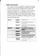
Table of contents Guide to this manual Table of contents Chapter 1 - Introduction ..~.,,...~~.,~.....,~~..~,.,~...,,.......~.....1 Features ~~...,..~~.,.....,.~.....~~..,...~~.., ~.....~~...,,.~.~.......,,..~~~.~~..~,..~~..,,.......,,.......~......~~. 5 Parts . . . .. . . .. . . .. .. . . .. Chapter 2 - Unpacking and setting up Choosing a place for the printer .............................................. Unpacking the printer ..............................................................
Chapter 4 - Printer reference Introduction ............................................................................. Using the control panel.. ........................................................ Making Electronic DIP Switch settings ................................ Selecting which emulation to use ........................................ Connecting the printer to your computer.. ..........................
Making adjustments 63 to the printer ....................................... Setting the print gap ..................................................................... Adjusting vertical alignment ........................................................ .63 .65 Testing the printer.. ................................................................ 67 Short test.. ....................................................................................... Long test.. .......................................
Appendix Specifications ........................................................................ Default Electronic DIP Switch settings.. ............................. Printer beep tones ................................................................ Interface pin outs .................................................................. Parallel interface ........................................................................... Serial interface ..............................................................
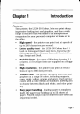
Chapter 1 Introduction Features This printer, the LC24-30 Colour, lets you print sharp, impressive-looking text and graphics, and has a wide range of features that will make it an indispensable companion for your personal computer at home or in the office. . High speed - the printer can print text at speeds of up to 240 characters per second. .
Easy set-up - Electronic DIP Switch mode allows you to make power-on settings from the control panel. Utility software for IBM PC and compatible computers also allows you to make these settings from your computer. Easy-to-use control panel - you can control the printer’s functions, make appropriate settings and determine the printer’s current status by means of the control panel. The panel has only three keys and is straightforward to use.
In addition to these features, the printer can print on a variety of different sizes and types of paper: single sheets (also called cut sheets), fanfold paper (continuous computer paper with holes in the edges), and multi-part forms (allowing you to print several copies at once). Single sheets can be up to 11” wide, and fanfold paper can be up to 10” wide; however, the maximum length of a printed line is limited to 8”. To use fanfold paper you need to install the push tractor unit, which.
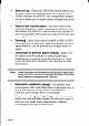
Paper guides Release lever Paper delivery selector Extension cover Interlace connector The printer level I The printer with the front cover removed Page 4
Parts The main components opposite. are shown in the two diagrams The paper guides and paper support hold singlesheets, setting their position so that they are fed into the printer correctly. The release lever grips single sheets as they are fed in. The lever should be pushed towards the back of the printer to hold single sheets properly, and released (pulled forward) when fanfold paper is in use. The front cover protects internal components reduces printing noise. The extension printer.
The platen guides the paper through the printer and provides -a solid surface against which the print head can make an impression on the paper. The adjustment lever lets you adjust the position of the print head for differing thicknesses of paper and for multi-part forms.
Chapter 2 Choosing Unpacking and setting up a place for the printer Keep the following points in mind when deciding where to put your printer. . Choose a firm, level surface where the printer will not be exposed to vibration. . Make sure that the printer is close enough to your computer for you to connect the two with your printer cable. . Allow 6” (15cm) of free space on either side of the printer.
Unpacking the printer There should be five items in the box: the printer, a color ribbon cartridge, the paper support, a 3 l/2” floppy disk and this user’s manual. If anything is missing, contact the store where you bought the printer and ask them to supply the missing part. It is a good idea to keep the original box and all the packing materials, in case you later need to pack the printer up again and send it somewhere at a later date.
Preparing the printer Place the printer in the spot you have chosen and carry out the following steps: Opening the front cover . Hook your fingers under the two small projecting tabs on either side of the front cover, grip the cover firmly and pull upwards. The front cover should open. . Note: Now pull the cover up and forwards so that it swings open as shown. If you wish, you can remove the front cover completely.
Installing the ribbon cartridge . Turn the tension knob on the cartridge clockwise, take the slack out of the ribbon. to Tension knob, Gently lower the cartridge into the cartridge holder. Make sure that the spindle on the cartridge holder fits into the socket on the base of the cartridge. .
. Carefully position the ribbon between the print head and the print head shield as shown. bon Print head shield Print head . Push down gently but firmly on the cartridge to make sure that it is properly in place. You should be able to feel a small amount of play (about 1/ 10” 2.5mm) in the cartridge as you press down on it. . Check that the ribbon is properly in place between the print head and print head shield. Turn the cartridge’s tension knob clockwise again to take up any remaining slack.
Close the front cover by swinging it down and pushing down on the raised parts at the rear so that it fits firmly into place. . Fitting the paper support . Fit the two tabs on the paper support into the rear cover slots as shown.
Connecting the printer to your computer The printer and computer must be connected with a cable. The computer sends the documents that you want to print to the printer via this cable. A cable is not supplied with the printer. Make sure that the printer and computer switched off before you connect them. are both You will probably use a parallel cable to connect the printer to your computer. The type of parallel cable you need is a standard 36-pin Centronics parallel cable.
Secure the connector Note: Page 14 with the clips as shown. Connection using the optional serial-to-parallel described in Chapter 5.
3 Setting up the printer in Windows The LC24-30 Colour is ideally suited for use with computers running Microsoft Windows system software. It works best with the newest version of Windows - Windows 3.1. If you are running a version of Windows earlier than 3.1, we recommend you upgrade your software to version 3.1. In particular, Windows 3.1 will allow you to use TrueType fonts. Fifteen TrueType fonts are included on the floppy disk packaged with this printer.
. Click on Install Unlisted or Updated Printer in the list, so that this option is highlighted. . Click Install. A window prompts you to put in the floppy disk supplied with the printer. . Insert the disk with the printer driver file on it and click OK. A new list of printers appears. (If you have inserted the disk into a drive other than drive A, you must type in the drive letter followed by a colon and a backslash, e.g. “B:\” before selecting OK.) . Select LC24-30 . Click OK.
r Setting up the printer in MS-DOS IBM PC’s and compatibles running MS-DOS will usually work with a printer connected to the parallel port without any special set-up. Try printing out some text as follows: . l . Turn on the printer and start up your computer. Type “PRINT” followed by the name of a text file, for example, “AUTOEXEC.BAT”, and then press Enter or Return. If a message “Name of list device [PRN]:” comes up on the screen, press Enter or Return again.
Chapter 3 Using the printer Loading paper The paper tray can hold up to 55 sheets of paper. To load the paper, use the following steps (for a description of how to load fanfold paper refer to page 76 of Chapter 5). . Move the release lever towards the back of the printer and pull the paper tray cover forward.
. . Page20 The paper guides move freely from side to side. Adjust the left-hand paper guide to the position you want. Pick up your stack of paper.
. Cut sheet paper can sometimes stick together, causing problems when the paper is drawn through the printer. To prevent this, flick through the stack of paper with your thumb. This helps ensure that each sheet of paper is loose within the stack and will be fed through the printer separately. . Now make sure that all the sheets are properly lined up by tapping the end of the stack gently but firmly on a flat surface, such as a table-top.
Now place the paper in the paper tray. . Paper guides . Adjust the right-hand paper guide so that stack fits snugly between the guides. The must be able to slide down freely into the but should not be able to move from side . Push the paper tray cover closed. Page 22 the paper paper printer, to side.
. Push the paper delivery selector up and back. Printed pages will now be delivered in a stack, face down. When you turn the stack of printed pages right-side up, the sheets will be in the order in which they were printed. Papa , delivery . Pull out the extension tray and pull out the stack wire to support the printed sheets.
Ready mode and Not-Ready mode The printer is in “ready” mode when it is ready to receive and print documents sent by the computer. When the printer is in “not-ready” mode, you can use the control panel keys to change various printer settings. In “not-ready” mode, the printer cannot print anything. When the printer is on, the READY indicator light on the right-hand side of the panel indicates whether the printer is in ready mode, or not-ready mode.
You can press the (READY]key to switch the printer between the two modes. Pressing (W] once puts the printer in ready mode: pressing [READV]again puts the printer in not-ready mode. Using the control panel The control panel’s purpose is to allow you to control the printer’s various functions and to see at a glance the printer’s set-up.
The green READY light on the right-hand side of the panel indicates whether the printer is in ready mode or not-ready mode, as already mentioned. The other six lights are always either on or off. The three lights on the left indicate the currently selected font. If you are printing from Windows, this setting has no effect. However, if you are using MS-DOS, this setting can determine which font is used for printing. The settings of these three lights (on or off) indicate the current font selection.
Printing out your documents Printing documents is dependent tem (Windows or MS-DOS). on your operating sys- In Windows Unless you select otherwise in the application, Windows applications always print to the current Windows Default Printer. You have probably already made the LC24-30 Colour the Default Printer when you installed the printer driver file, (see page 15 of Chapter 2). If you did not, you can set it as follows: . Double-click dow. the Control Panel icon in the Main win- .
Start up the application program and select a printer. Choose one of the following in the order of preference shown: Star LC24-30 Colour Epson LO-860/l 060 The shaded printers are not color printers. You will not be able to print in color, if you select one of them. If none of the printers above is listed, choose one of the following, in order of preference: These two printers are not color printers. You will not be able to print in color, if you select one of them.
Using different fonts You can vary the appearance of your printed text by using different fonts. If you are unfamiliar with fonts (or typefaces), please refer to the section Introduction to fonts on page 50 of Chapter 4. The way in which you select different fonts depends on whether your computer is running Windows or MS-DOS. If you are using Windows, you will select fonts from your applications software, e.g. your word-processing program.
In MS-DOS If you are using a computer running MS-DOS, you can use the control panel to select one of the 6 typeface families built into the printer. Roman : 1234567890 ABCDE abcde Sanserif : 1234567890 ABCDE abcde Courier : 1234567890 ABCDE abcde Prestige : 1234567890 ABCDE abcde SC/Lip-t : 1234567890 ABCDE aJxxk Draft : 1234567890 abcde ABCDE The lights on the control panel’s left-hand column show the selected font. The lights come on and off as you press the (FONT]key.
Similarly, if only the middle light or bottom light is on, Courier or Script is selected. If two lights are on, the font whose name is between the two lights is the selected font. For example, if the lower two lights are on, Prestige is the selected font. Micro Feed ALT 0 Macro A a Zoom FF Prestige typeface selected Similarly, selected. if the top two lights are on, Sanserif is If none of the lights is on, the draft font is selected. To select a font for printing, use the following steps: .
Using other printer features There are a number of other printer features that you may want to use. These features include the ability to use different types of paper, the ability to adjust the position of the paper very accurately, and the zoom feature, which allows you to print documents at a reduced size. These are all described in Chapter 4, Printer reference. Dealing with printing problems The LC24-30 Colour is designed to be easy to use and trouble-free.
Chapter 4 Printer reference Introduction This chapter is intended as a comprehensive guide to the printer’s functions. It covers a wide range of topics, some that have been briefly described in the first three chapters and some that are new. Among the topics covered are the following: . Using the printer’s control panel . Making power-on Switch settings) . Selecting which emulation . Setting up the printer to work with your computer . Using different fonts . Using different types of paper .
Using the control panel The control panel allows you to control the printer’s various functions and to see the printer’s current set-up. The control panel has users, since Windows such as font selection. printer’s control panel tions. more significance for MS-DOS takes care of feature selections, MS-DOS users must use the to manage the printer’s func- Micro Feed V Quiet p$y&g+ ALT l L Macro A Zoom FF Control panel The panel has three keys: (FONT],[PAPER] and [READY).
such as the current font. The light is on when the printer is in ready mode. It flashes when it is in notready mode. The three lights arranged in the left-hand column of the panel show which font is currently selected. If a single light is on, the font next to that light is the currently selected font. For example, if the top light only is on, Roman font is selected. Similarly, the middle and bottom lights on their own signify that Courier and Script respectively are selected.
the lights are off if these features are not in effect. These features are explained later on in this chapter. The control panel is also used to make Electronic DIP Switch settings. These feature settings come into effect each time the printer is switched on. See the following section for an explanation make Electronic DIP Switch settings. Note: Page 36 of how to If you are using Windows, most printer settings, such as Font and Zoom, will be determined by the software you are using.
Making Electronic DIP Switch settings Dot-matrix printers usually have rows of thin, two-position switches (DIP switches) with which you can select various power-on settings, such as emulation (Epson or IBM), default font and print quality (Letter-Quality or draft). The LC24-30 Colour does not have DIP switches. Instead you can use the control panel directly to select imaginary DIP switches and make power-on feature settings.
Micro Feed ALT l Macro A Zoom FF Electronic DIP Switch Dl (print quality) selected Press the [FONT] and [PAPER] keys until the letter and number corresponding to the desired setting are shown. The READY light shows the current switch setting: ON or OFF. Use the (READY]key to change the setting.
When the printer is shipped from the factory, all switch settings are set to ON, except for Bl, the graphics direction, which is set to OFF (uni-directional printing).
EDS setting Function ON OFF El I I E2 LO font selectIon I I See below I E3 Al E4 Reserved E5 Reserved - Emulation The LC24-30 Colour can “emulate” either an Epson LQ860 or an IBM Proprinter X24E. To “emulate” means to “perform in the same way as”. The two printers offer different sets of printable characters. Unless you are using an MS-DOS system and specifically need the IBM character sets, you will probably use the printer in Epson mode.
A3 - RAM usage If A3 is OFF, the printer is able to store patterns representing characters that you have defined with the Epson or IBM printer commands (see Chapter 7). If A3 is ON, the printer can store the data it receives from the computer. This speeds up the printing process. However, it cannot store user-defined character patterns. A4 - Color and zoom If A4 is ON, you can print in color and use the zoom feature. If it is OFF, these features are unavailable.
B2 - Paper out If B2 is ON, the printer can detect when there is no more paper and will stop printing. If B2 is OFF, the printer can print right down to the bottom of the page. However, there is also the danger that it may print past the end of the paper, which may cause damage to the print head and platen. B3 - Ink ribbon type If B3 is ON, you can use either a color or a monochrome ribbon. If B3 is OFF, you should only use a monochrome ribbon.
C4 and C5 - Print pitch Pitch is the number of characters in a one-inch line of text. If you want to print using 10 characters per inch text, C4 and C5 should be set to ON. The settings for other pitches are as shown in the table. Print pitch c4 c5 10 CPI ON ON 12 CPI ON OFF 15 CPI OFF ON 17 CPI OFF OFF Dl - Print quality If D 1 is ON, text is printed in Letter Quality mode. If it is OFF, Draft quality text is printed. Letter Quality allows you a choice of different fonts.
D3 to D 5 - IBM code page or international character set. Various special characters (for example, accented characters) are needed for different languages. For this reason, you can select variations on the standard character tables. These are known as code pages or international character sets.
El to E3 - LQ font selection If Letter Quality print mode is selected (Dl is set to ON), any of the following five fonts may be selected as the default font - the font that is current when the printer is powered on.
Selecting which emulation to use The LC24-30 Colour can emulate both Epson and IBM dot-matrix printers. This means that the software applications you use on your computer can treat the printer as if it were an Epson or an IBM printer. As a result, when you select a printer in your software application, you can select certain types of Epson or IBM printer instead of a Star printer.
To change the setting back to Epson mode, simply perform the reverse procedure. From now on the printer will turn on in the mode you have selected. Connecting the printer to your computer There are two stages to connecting the printer and your computer. First you must physically connect them with a cable. Secondly, you must set up your software to print to the printer. Choosing which type of cable to use Before connecting your printer to the computer, make sure that both are turned off.
If you are using the serial-to-parallel converter, you will need to make some switch settings on the converter and corresponding serial port settings in Windows. This is described in the section Serial- to-parcdZeZ interface conuerter in Chapter 6. You should now be able to print from your Windows applications. Try printing a document from an application, following the steps outlined on page 27 of Chapter 3. If you have problems printing, refer to Chapter 6, Troubleshooting.
When you can print using the MS-DOS print command, try printing from an application. Start up an application program, such as your wordprocessor, and select a printer to print to, as described on page 27 of Chapter 3 (you may also need to consult the application’s manual). Now try printing a document from your application. If you have problems printing either with the PRINT command or from your application, refer to Chapter 6, Troubleshooting.
Using fonts and varying the appearance of text Introduction to fonts and typefaces A font is a collection of characters (letters, digits and punctuation symbols) of a particular design and size. The typeface of a font is the design style of the characters. The typeface lends a font its distinctive appearance. There are hundreds of different typefaces in existence. Commonly-used typefaces include Times, Palatino, Helvetica, Univers and Courier. Some examples of different typefaces are shown below.
character’s design. As a result, two different sentences that contain the same number of characters will occupy the same width if printed using a monospaced font, but will usually have different widths if a proportionallyspaced font is used. An example Identical sentence number in Courier. of characters. An example sentence in Bookman. Identical number of characters. Pitch The pitch of a monospaced font is the number of characters printed per inch.
Scalable fonts Each character in a scalable font is defined as an outline shape. The computer converts the outline shape to a matrix of dots that forms the printed character. Hence, scalable fonts, such as the TrueType fonts on the floppy disk accompanying the printer, can be displayed onscreen and printed at any size. In Windows Installing True Type fonts To install the TrueType fonts that are on the floppy disk accompanying this printer, follow the procedure below.
Selecting different fonts If you are running applications software under Windows, you will select fonts from within your application (refer to your application’s manual for details). Your applications software manual will tell you the various ways in which you can type-set your text on-screen so that it is ready to print out on the printer. Your Windows system already includes several fonts, such as Arial, Times New Roman and Symbol. You can also use the 15 TrueType fonts included with the printer.
Unless you have altered the setting, the pitch is set to 10 characters per inch. You can also select character pitch from software applications programs. Consult the application’s manual for details. Preventing software font selection To prevent the font selection from being altered by a software application and to ensure that selections can be made from the control panel only, power up the printer while holding down the (FONT] key. The printer will sound a very short beep as it comes on.
Using different types of paper You can use any of the following types of paper with your LC24-30 Colour printer: single sheets, fanfold paper and multi-part forms. Single sheets are individual, unconnected pieces of paper. They are also referred to as cut sheets. Up to fifty-five single sheets can be stacked in the paper tray and fed automatically into the printer.
You can also print using sheets of labels. We recommend that single sheet labels are used in preference to fanfold label paper. Note: Do not reverse feed label sheets.
Useful printing features Portrait and landscape printing You can load paper into the printer in either portrait (upright) or landscape (widthwise) orientation, provided that the width of the paper does not exceed 11”. Hence, you can load Letter-sized paper in landscape orientation, but not A4 paper. Note: Although Letter-sized paper can be loaded into the printer in either landscape or portrait orientation, the print width is limited to 8” (20.3cm).
Pausing printing To temporarily interrupt printing, press the (READY]key. This puts the printer in not-ready mode. This allows you to check your print-out or change a setting using the control panel. To resume printing, press the (READY) key again to put the printer back in ready mode. Parking fanfold paper If you are using fanfold paper and want to switch to single sheets temporarily, you can do so without removing the fanfold paper. This is known as “parking” the fanfold paper.
e Controlling the paper position There are a number of ways in which you can adjust the position of the paper in the printer. You can feed paper through a line at a time (paper feed), eject the current page (form feed) and feed the paper forwards and backwards in very small steps (forward and reverse micro feed). You can also adjust the top-of-form position (the position at which printing starts on each new page). You can set separate top-of-form positions for single sheets and fanfold paper.
Reverse micro feed To feed the paper through the printer in reverse in small steps, first put the printer in not-ready mode. Hold down the (READY]key and press the [FONT]key. Each time you press the [FONT]key, the paper is fed backwards by a small amount. Setting the auto load position Each time the printer feeds in a sheet of paper, it always starts printing at the same distance from the top of the page. This is referred to as the auto load position.
Selecting Zoom mode print size You can print at either 50% [half) or 67% (two-thirds) normal size by using the Zoom mode. This is useful for printing wide documents, such as spreadsheets, on a single sheet. Change the zoom size as follows. Put the printer in not-ready mode. Hold down the (FONTj key and press the [PAPER] key to cycle through the three zoom settings. The zoom light indicates the current selection as shown in the table below.
Quiet indicator will light up, indicating that the printer is in Quiet mode. Printing will be slightly slower. To turn off Quiet mode, press the (FONT] key again while the printer is in ready mode. The printer will beep again to indicate that you have quit Quiet mode.
Making adjustments to the printer Setting the print gap Paper comes in different weights, normally quoted in gsm (grams per square meter). 60 gsm and 90 gsm are typical figures. Heavier paper is thicker. Multi-part forms are generally thicker than single sheets or ordinary fanfold paper. The distance between the print head and the platen can be adjusted to suit the current paper thickness. The adjustment lever is located inside the printer’s main body, at the right-hand side of the platen.
It is a good idea to try out different settings in order to find out which setting gives the best print quality results. The table below gives recommended Paper type Weight of each sheet settings: Total thickness Position 2or3 Single 14-24 Ibs (52-90 gsm) 0.07-0.12 mm 2-PlY 1 I-14 Ibs (40-52 gsm) 0.12-0.14 mm 3 3-P/Y 1 l-l4 lbs (40-52 gsm) 0.18-0.21 mm 4 Note: Page 64 Persistent use of the wrong setting may drastically reduce the print head life.
Adjusting Note: vertical alignment You may never have to use this function. Use it only if graphics print-outs appear strange (as in the illustrations below). After you have been using your printer for some time, you may find that when you print graphics, the printed dots are slightly out of line with each other.
*** DOT ADJUSTMENT LQ -3 SETTING *** : [PAPERJ~ +[FONT] Each time you press either of these two keys, the printer prints a new test line and a new offset value. If you are using fanfold paper, the printer will reverse feed the paper before printing the test pattern again. After printing the pattern, the printer will feed the fanfold paper back up again so that you can see it clearly.
Testing the printer Short test A short test prints out the version number of the software contained in the printer’s ROM, followed by seven lines of text. Each line is offset by one character from the line above. If the color ribbon is in use, each line will be printed in a different color. To perform a short test, power up the printer while holding down the [READY]key. The test print out should appear as shown below. Note: This test prints across the entire width of the carriage.
c This test prints across the entire width of the carriage. It is a good idea to make sure that the printer is loaded with the widest possible paper available to avoid the possibility of damage to the print head or the platen. This test can generate many lines of text and graphics, so it is a good idea to use continuous fanfold paper rather than single sheets. The test continues indefinitely until the printer is turned off.
. When the printer stops printing, put the printer in not-ready mode. The printer now prints the final line of the hexadecimal dump. . To resume normal operation, turn the printer off and on again. (Unless you switch it off and on the printer will continue to print in hexadecimal).
Chapter 5 Options The two optional accessories that you can purchase with your LC24-30 Colour printer are the push tractor unit (PT- 1OQ), which allows you to print on fanfold paper (continuous stationery), and the serial-to-parallel interface converter (SPC-8K), which allows you to connect the printer to your computer via your computer’s 25-pin serial port. Note: Make sure that the printer is switched off, when installing either the push tractor unit or the serial-to-parallel interface converter.
Push tractor unit Installing the push tractor unit The push tractor unit allows you to print on continuous fanfold paper up to 10” wide. The push tractor unit consists of two end pieces joined by two silver metal rods. The metal rods have two black sliding tractor units and a black sliding support piece mounted on them. Install the push tractor unit using the following steps: . Make sure the printer is switched off. .
. Hold the push tractor unit with your thumb and forefinger on the ridges near the top and with the slot facing towards you. Ridges_ . Hook the slots in the end pieces over the shaft just behind and above the platen roller.
. Using your forefinger and thumb squeeze the end piece levers against the rear part of the end pieces. Rotate the tractor feed unit downwards until the bottom of the levers fit snugly into the indentations in the metal plate inside the printer body.
. Release the two levers and check that the tractor unit is properly secured. The unit is now locked in place. Make sure that the covers on both tractors are closed. . Close the rear cover by swinging it forwards and upwards. Click it firmly back into place. . Close the front cover.
Loading fanfold paper Position the stack of fanfold paper behind the printer. Turn the printer off. Pull the release lever forward. If there is a single sheet that has been fed into the printer, remove it. Open the front cover by hooking your fingers under the two small projecting tabs on either side of the front cover. Grip the cover firmly and pull upwards. The front cover will come loose. Now pull the cover up and forwards so that it swings open.
Lock the tractors in position by pushing the levers back down again. Open the covers on both tractors and position the paper by aligning the holes in the paper with the pins on the tractors. Ensure that the paper is properly aligned on the tractor pins. Otherwise, it may tear or jam. Close the tractor covers. If necessary, make any final adjustments to the paper position. Release one or both of the tractors by pulling the gray levers forward and moving the tractors sideways.
. Note: Press the [PAPER] key. The fanfold paper will be fed in to the starting position (if you want to adjust this position, use the procedure for setting the auto load position, described on page 60 of Chapter 4). Keep the release lever in the forward position while printing on fanfold paper.
Printing on fanfold paper Two useful features of the LC24-30 Colour that facilitate the use of continuous stationery are paper parking (fanfold paper can remain installed in the printer while you temporarily switch to printing on single sheets), and the tear-off function (you can remove printed output without losing the current paper position). These are described in the following sections.
Perforation Bottom of Form 0 a 75 mm 0 0 If you need to use continuous multi-part forms, use the type which has both side edges glued together. Do not use forms with more than three parts. Make sure that the print gap is correctly set for the thickness of paper that you are using. Setting the print gap is described on page 63 of Chapter 4.
Parking paper If you want to use single sheets, but do not want to remove the fanfold paper, you can “park” the fanfold paper. . Tear off the paper at a perforation, so that not more than half a page protrudes above the paper delivery selector (if necessary, put the printer in not-ready mode and feed paper through by pressing the [@El?) key until a perforation is just visible above the paper delivery selector). . Make sure that the printer is in ready mode and that the release lever is forward.
Using the tear-off function You can remove finished fanfold output without disturbing the current position of the paper. I . Make sure that the printer is in ready mode, hold down the (READV]key and then hold down the [PAPER) key. Keep both keys held down. The printer starts to feed the paper through the printer. . Release both keys. The printer automatically into not-ready mode. . Tear off the paper, using the paper delivery selector’s tear-assist edge. . Press the (READY)key again.
Serial- to-parallel interface converter You can connect the printer to your computer via one of your computer’s serial ports using the serial-to-parallel converter (SPC-8K). To do this, you will also need an additional serial converter cable. To connect the printer to your computer using the serial-to-parallel converter, proceed as follows (you will also find it helpful to refer to the SPC-8K User’s Manual and your MS-DOS or Windows User’s Guide). Connecting .
. Plug the interface converter’s Centronics connector into the socket on the side of the printer. Secure it with the retaining clips. . Connect the interface connector’s 25-pin D-type connector to one end of the serial converter cable. . Plug the other end of the serial converter cable into one of your computer’s serial ports. The computer’s serial ports are usually labelled COM 1, COM2 etc. COMl is normally a g-pin serial port and COM2 is normally a 25-pin port. COM2 ............. ............ .
Setting the converter’s DIP switches . Set the DIP switches on the converter so that the settings match the settings you intend to make on your computer. . The DIP switches on the serial-to-parallel converter correspond to the following settings. The equivalent settings that you will need to make in MS-DOS’s AUTOEXEC.BAT file, or in the Ports option in Windows’ Control Panel, are also listed. The converter’s default settings are shown in gray.
Protocol (or “handshaking”) is the communications convention used between the computer and printer to regulate the flow of data. DTR is the most commonly used protocol. Switch 3 1 Switch 4 Protocol ON ETXIACK 1 I OFF Baud rate is the rate in bits per second at which data is sent to the printer. Typically 9600 or 19200 is used.
Setting up a serial connection Make settings on your computer to correspond to the settings you have made using the DIP switches. On a Windows computer . Double-click the Control Panel icon in the Main window. . Double-click the Printers icon . Make sure that LC24-30 Installed Printers list. . Click on Connect . Click on the serial port (COMn) to which the serialto-parallel converter is connected. . Click OK to return to the Printers window. . Click Close to return to the Control Panel window.
On an MS-DOS computer If you are using an IBM PC or compatible running MS-DOS, edit the AUTOEXEC.BAT file to include a line that reads: MODE LPTl:=COMn: n stands for a number: 1, 2, 3 etc. COMn must match the name of the serial port to which the serial-to-parallel converter is connected. Usually it will be COM2. This line sends printer output to the COMn serial port.