L.- i-. ., L.. I.d L- XR-1020 XR-1520 MULTI-FONT L. LI USERS MANUAL i .
Federal CommunicationsCommission Radio Frquettcy Interference Statement lllisq . em has been tested and found to compIy with the limits for a Class B digital device. pursuant to Part T1 of FCC Rules. ‘lltese limits ate designed to provide masonable ptotection against harmful interfemce in a residential installation. ‘lIis equipment generates, uses and can radiate radio f ency e-rmgy and. if not installed and used in aeeotdmce with the.instmctions. may cause. harmful inte7 emnce to radio eanmunications.
HOW TO USE THIS MANUAL This manual is organized into eleven chapters. To learn how to make the best use of your printer you are urged to read through chapters 2 through 6. The remaining chapters may be treated as a reference guide for programming operations, etc. It assumes a degree of acknowledge of the operation of computers (for instance, it assumes you know about hexadecimal numbers).
Chapter 6 - Setting the Memory Switches This chapter explains how to set the Memory Switches to make system settings on the printer. Chapter 7 - Printer control commands This chapter explains the different emulations provided by your printer, and the software commands used to drive it. This section is of use if you are writing or modifying programs to take advantage of the printer’s features. Chapter 8 - Download characters This chapter explains the procedures to create your own characters.
TABLE OF CONTENTS Chapter 1 INTRODUCTION Features of the printer Printer components Font style example Chapter 2 SETTING UP THE PRINTER Locating the printer Unpacking and inspection Setting up Mounting the platen knob Install the ribbon cartridge Connecting the interface cable Chapter 3 OPTIONAL ACCESSORIES Automatic Sheet Feeder Single-Bin Automatic Sheet Feeder Dual-Bin Automatic Sheet Feeder Pull Tractor Unit Interface Cartridges DIP switch functions on the Serial Interface Cartridge Chapter 4 PAPER I
Chapter 5 CONTROL PANEL OPERATIONS Buttons and indicators ON LINE button PAPER FEED button SET/EJECT/PARK button PITCH button MODE button FONT button Power-up functions Short test mode Long test mode Print area test mode Pitch lock mode Font lock mode Pitch and Font lock mode Hexadecimal dump Switch combination functions Form feed Top of form Forward micro-feed Reverse micro-feed Changing the auto loading value Clearing the buff&All reset Selecting the print color Selecting the ASF bin number Store macro de
Chapter 7 PRINTER CONTROL COMMANDS Font control commands Character set commands Character size and pitch commands Vertical position commands Horizontal position commands Graphics commands Download character commands Color selection commands Other printer commands Chapter 8 DOWNLOAD CHARACTERS Defining your own draft characters Defining the attribute data Assigning the character data Sample program Defining your own NLQ characters Assigning the character data with the Standard mode Assigning the character
c -.
Chapter I INTRODUCTION This printer has a full complement of features, making it an excellent partner for a personal computer. It supports the Epson/IBM printer commands and character sets, enabling it to print just about anything your computer can generate, both text and graphics. FEATURES OF THE PRINTER Some of main features are the following: l t. . l l .
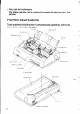
l Easy care and maintenance The ribbon cartridge can be replaced in seconds the print head in a few minutes. PRINTER COMPONENTS To get acquainted with the printer’s components and capabilities, refer to the information on the following pages. TI-;ICIOI- h Paper pide .
Tractors Aligns single sheets (cut forms) to help the printer detect when paper is inserted. Releasespressureonthepaper.Thislever must be back for fanfold forms, and forward for single sheets. Protects the print head and other internal components of your printer. Protects the tractor feed unit and separates incoming and outgoing fanfold forms. For inserting single sheets of paper. Assists when tearing fanfold forms at the perforation.
FONT STYLE EXAMPLE The following example shows the many font styles your printer can print. D r H S a f t D r :.:I :I. ;: a f t 1.1: ) ‘;j;: -<.!::; 5, ‘:? ;;;; ‘;? <; B;::; :.:I;:::; ,i:;. i;i;c, .-., /(( y-y i,z ),_,j /- -y ! ... i !x, ,. 3 ,,.,..,,.. / ..;,>:; ...(j.. .; c I,, ‘! jri :,,j i:::. ; <..; ! i ,,, ,,.! ?...; ,,,, /. / .;::. i::; :.,,, >.,., F;:: i ,.;;, i \ _,. ,,j ].., _,. i i ‘~/~:i’~~,!:::li::;;,,““l”:i’,;l(;;::‘i::jl..j .,, :j: ,,,!I..:~I,,,i’f~~:,~,:,,::;::,il::.I.
chapter 2 SETTING UP THE PRINTER This chapter describes the following procedures to set up your new printer. If you have optional accessories, refer to chapter 3 after setting up the printer. l Locating the printer l Unpacking the carton box l Mounting the platen knob l Installing the ribbon cartridge l Connecting the printer to your computer LOCATING THE PRINTER Before you start unpacking and setting up your printer, make sure that you have a suitable place on which to locate it.
- UNPACKING AND INSPECTION Now unpack the contents of the shipping carton, and check each item in the box against Figure 2- 1 to make sure that you have everything @h&z should be five items). If any of these items are missing, contact your supplier. V - - FrgutuZ-7. Chedc to make sure you have all five items: 1) Printer, 2) Paper guide, 3) Platen knob, 4) Ribbon cartridge. and 5) User’s manual.
The optional accessories which you may have ordered with your printer are: l Color ribbon cartridge (X9cL) l Serial interface cartridge (IS-8XL) l Buffered parallel interface cartridge (IP- 128XL) l Automatic sheet feeder (SF-lODMII/l5DMII, SF-lOFU4II/l5RMII) l Pull tractor unit (PT-lOXM/lSXM) For details of the optional accessories, refer to Chapter 3.
- SETTING UP Place the printer in the desired location, and remove all packing material from inside the printer cover. This packing material is intended to prevent damage to the printer while in transit. You will want to keep all the packing material, along with the printer carton, in case you have to move the printer to a new location. Mounting the platen knob The platen knob is packed into an accessory box with other accessories for the Wide carriage printer.
Install the ribbon cartridge Open the front cover by lifting up the back using the two grips on either side, then swing down the transparent part (see Figure 2-3). Flgurr 2L3. Open the front cover, and swing down thetransparent part. Now install the ribbon with the following procedure. (If you want to print with color, install the optional color ribbon cartridge, X9CL.) 1. Turn the tension knob clockwise on the ribbon cartridge to tighten the ribbon if it is slack. 2.
Print head Print head shield - - Figure Z-4. Installing the ribbon cartridge. After you have installed the ribbon cartridge, close the front cover. Leave the front cover closed during normal operation. The cover keeps out dust and dirt and reduces the printer’s operating sounds. Open the cover only to change the ribbon or make an adjustment. Connecting the interface cable Connect the printer to your computer using a standard Centronics parallel interface cable.
Interface cable F@m Z-5. Connecting the interface cable. 3. Move both clips inside the extended prongs on the sides of the plug until you hear a click. Figurn 2-6. Move the clips until you hear a did. 4. Connect the other end of the interface cable to your computer. Use your computer instructions to attach the interface cable. NOTE: Because you need your computer when you start printing, ensure that it is completely installed. Plug the printer into a suitable outlet.
” - MEMO
Chapter 3 OPTIONAL ACCESSORIES You can select the following accessories as option. l Automatic sheet feeder (SF-lODMII/15DMII, SF-lORMII/ 15RMII) l Pull tractor unit (PT-lOXIW5XM) l Serial interface cartridge (IS-8XL) l Buffered parallel interface cartridge (IP-128XL) This chapter describes how to install these optional accessories. NOTE : When you install or remove the optional accessories, turn off the power switch.
P 2 Transparent part - - Figwv 3-l. Open the front cover, and swing down the transparent part. - Figum 32 Open the rear cover, and remove it. 4. A stacker is included with the Automatic Sheet Feeder. Attach the hook at the top of the stacker to the Automatic Sheet Feeder. Then push the lower section of the stacker down into position, and engage the lower hook as shown in Figure 3-3.
i . F&m 33. Attach the stacker to the Automatic Sheet Feeder. 5. Tip the Automatic Sheet Feeder forward slightly and put the feeder into place behind the printer platen roller. 6. Lower the rear side of the Automatic Sheet Feeder and attach it to the platen shaft. Automatic Sheet Feeder . . I. Frgum 34. Mount the Automatic Sheet Feeder to U-mpdntw.
I - 7. Close the front cover with the transparent part in the open position. F/gum 3-S Close he front cover. 8. Insert the hopper attachment by hand into the holders on top of the hopper support section as shown in Figure 3-6. opper attachment Figum 36. Insert the hopper attachment.
9. Squeeze the sides of the stacker attachments lightly, and insert into the holders on the front part of the sheet feeder. Figum 3-7. insert the stacker attachments, NOTE : Set the paper guide and rear cover aside carefully after they have been removed from the printer. Reverse the procedure described above when removing the Automatic Sheet Feeder.
Dual-Bin Automatic Sheet Feeder (SF- 1ORMWI5RMII) The procedure to mount the Dual-Bin ASF is: 1. Open the front cover by lifting up the back using the two grips on either side, then swing down the transparent part (see Figure 3-l). 2. Open the rear cover by lifting up the front using the two grips on either side, then remove it upward. If the paper guide is installed, remove it before taking off the rear cover. 3. Move the bail lever on top of the printer forward to open the paper bail. 4.
NOTE : Set the paper guide and rear cover aside carefully after they have been removed from the printer. Reverse the procedure described above when removing the Automatic Sheet Feeder.
PULL TRACTOR UNIT (PT-1 OXM/15XM) You can use the FW Tractor Unit to print on fanfold forms or multi-part forms. The procedure to mount the Pull Tractor Unit is: 1. Open the front cover by lifting up the back using the two grips on either side, then swing down the transparent part (see Figure 3- 1). 2. Open the rear cover by lifting up the front using the two grips on either side, then remove it upward. If the paper guide is installed, remove it before taking off the rear cover. 3.
w I Pull Tractor Un’ L . .w.. L . . i Flgum 3-W. Mount the Pull Tractor Unit onto the printer. NOTE : Set the paper guide and rear cover aside carefully after they have L been removed from the printer. Reverse the procedure described above when removing the FWl Tractor Unit. L.
INTERFACE CARTRIDGES You can use the RS-232 Serial Interface with the optional Serial Interface Cartridge (IS-8XL), or extend the print buffer by installing the .optional Buffered Parallel Interface Cartridge (IP-128XL), instead of the Standard Interface Cartridge. If you want to use the Serial Interface Cartridge, set the DIP switches on the board before install it to the printer. 1. Turn off the power switch and disconnect the power cord from the power source. 2.
DIP Switch Functions on The Serial Interface Cartridge It is necessary to make compatible the data transfer conditions between the computer and the serial interface board with the DIP switch settings on the serial interface board. Following table shows the functions of the DIP switches on the Serial Interface Caruidge. switch .
..
chapter 4 PAPER INSTALLATIONAND USE This chapter describes instructions forprinting such as selecting paper types, adjusting the printing gap, and installing paper. SELECTION OF PAPER .- Your printer accepts any of the following papers: l l l l Single sheets (cut forms) and stationery Use the friction feed or the optional Automatic Sheet Feeder. Fanfold forms Fanfold forms have holes along the sides and perforations between the sheets.
Figure 4-l shows the recommended print area for each type of papers. Single sheets Fanfold forms 20 mm IX m 5mm - Smm - 23 mm c*XO mm for Push Feed) Figuru 41. Recommended print area for acceptable papers. ADJUSTING THE PRINTING GAP The distance between the print head and the platen can be adjusted to accommodate different paper thicknesses. To make this adjustment, open the front cover. The adjustment lever is located at the left side of the printer mechanism.
Figutv42 Location of the adjustment lever. The following table provides the recommended lever positions for each paper types as a reference. LOADING FANFOLD FORMS This printer accepts fanfold forms up to 10” wide for the normal carriage printer, and up to 16” wide for the wide carriage printer.
Loading the paper from the rear of the printer (Push feed) You can load the fanfold paper with the internal push tractor unit. 1. Place a stack of fanfold paper behind and at least one page-length below the printer. 2. Turn the printer’s power OFF. 3. Push the release lever backward. This has the effect of releasing the paper from the platen roller, and engaging the tractor feed. 4. Remove the paper guide and put it aside for the moment. 5.
Tractor cover Figure 44 Clamp lever Mount the fanfold paper over the tractor units. 9. Now close the tractor covers, again making sure that the paper holes are aligned with the pins on the tractor units. If they are not aligned properly, you will have problems with paper feeding, possibly resulting in tearing and jamming of the paper. 10. Turn on the power using the switch located at the front of the printer. The printer will beep, indicating that the paper is not yet fully loaded.
- Hgurv 4-5. Mounting the paper guide tor tantold torms. Loading the paper from the bottom of the printer You can load the fanfold paper from the bottom of the printer with the optional Pull Tractor Unit. 1. Install the optional Pull Tractor Unit as described in Chapter 3.
2. With the tractor covers open, mount the paper from the bottom of the printer, by aligning holes with the pins on the tractor unit. F/gum 4-7. Mount the fanfold paper from the bottom of the printer. 3. Adjust the spacing of the tractor units by sliding them along the bar, using the clamp lever at the back of each unit to release and lock them in position. When the lever is up, the unit is released, and when it is down, the unit is locked. 4.
4. Open the transparent part of the front cover, and remove the paper guide and the rear cover. 5. With the tractor covers open, mount the paper by aligning holes with the pins on the tractor unit. 6. Adjust the spacing of the tractor units by sliding them along the bar, using the clamp lever at the back of each unit to release and lock them in position. When the clamp lever is up, the unit is released, and when it is down, the unit is locked. 7.
Clamp lever Pull tractor unit ractor cover Figum 4-O. Mount the fanfdd paper to the Pull Tractor Unit by turntng ttm platen KtIOD. 12. Adjust the spacing of the optional tractor units by sliding them along the bar, using the clamp lever at the back of each unit to release and lock them in position. When the lever is up, the unit is released, and when it is down, the unit is locked. 13.
Lever mpprr -. \ Platen knob Frgurr 4-70. HemOVa the IeVBT stopper, afM ttgnten the paper. 16. Push the release lever backward, and remount the lever stopper to the original position. Paper parking After loading fanfold paper with Push feed mode, you do not have to unload it when you want to print on a single sheet. The printer will “park” it for you if you follow the procedure below. 1.
Release lever Paper pide F/gum 411. Tear off the printed fanfold paper. 6. Mount the paper guide in the upright position. Now you can load single sheets. The fanfold paper remains parked at the back of the printer. NOTE: You cannot park the fanfold paper if you have loaded it using the optional Pull Tractor Unit. Paper unparking When you want to resume using fanfold paper, the procedure is as follows. 1. 2. 3. 4. Remove all single sheets from the printer.
LOADING SINGLE SHEETS This section will take you through the procedures for loading single sheets of paper. Loading the paper without optional accessories If you are using the optional Automatic Sheet Feeder, refer to next section. 1. Place the paper guide in position by inserting the tabs, located on the bottom of the assembly, into the slots on the rear cover of the printer. - Paper guide - - Figum d-12. Mounting the paper guide for single sheets. 2.
5. Place a single sheet between the guides, placing the side on which you want to print towards the back of the printer. Gently push the paper down in the guides until you feel it stop. 6. Now press the 15EZZ220T 1 button. The paper will be fed into the printer and adjusted past the print head to a position ready for printing. 7. If you want to set the paper to a different position, set the printer off-line by pressing the 1 ON LINE j button, then set the paper position by using the micro-feed function.
Loading the paper with optional Automatic Sheet Feeder If you are not using the optional Automatic Sheet Feeder, refer to the previous section. 1. Install the optional Automatic Sheet Feeder as described in Chapter 3. - F/gun 4-14. Install the optional Automatic Sheet Feeder. 2. Use the printer’s Memory Switchmode to select ASF. (For details, please refer to Chapter 6.) 3. If fanfold paper has already been loaded in the printer, park the paper through the rear slot. 4.
Paper loading lever [Single-Bin] Figum 4-M Make ready to load paper. 6. Adjust the left paper guide to the desired left position by moving it horizontally in either direction. (Unlock the paper guides by pressing down on the locking levers in case of Dual-Bin ASF.) 7. Lock the left paper guides in position by moving the locking lever up for the Dual-Bin ASF. F/gum 4-18. Adjust tie paper guides to accomrmdate the width of the paper.
m - 8. Adjust the right paper guide to accommodate the width of the paper. The guides should be adjusted to restrict the amount of horizontal play while allowing the paper to slide up and down freely between the two paper guides. The ideal distance between paper team and paper guides is 0.25 mm (0.01”) on both sides at the narmwest part of the paper guides. 9. Fan the paper stack and square it off properly before inserting it into the Automatic Sheet Feeder. - Figurn 417.
Chapter 5 CONTROL PANEL OPERATIONS The control panel buttons can be pressed individually to perform the operations indicated by their names. Other functions can be achieved by holding these buttons down when you turn the printer’s power on, or by pressing the control panel buttons in combination. This chapter explains all the button and indicator functions.
ON LINE button The 1 ON LINE 1 button sets the printer on-line and off-line. The status changes each time you press the button. When the printer is on-line, it can receive and print data from the computer. When the printer is off-line, it stops printing and sends the computer a signal indicating that it cannot accept data. - The printer powers up in the on-line status if paper is loaded. If paper is not loaded, the printer powers up off-line with the PAPER indicator illuminating.
If you press this button while on-line, this will alternately flash the QUIET indicator. When in Quiet mode with the QUIET indicator lit, the printer will print slightly slower, but at a reduced noise level. SET/EJECT/PARK button NOTE: This button has no effect if the bottom feed mode is selected. Pressing this button causes the printer to begin paper loading if the paper has not loaded while in the off-line state.
MODE button This button allows you to select the printing mode. Remember that the printer must be off-line for you to do this. Successive presses of this button will illuminate (and select) the following options in order: L Print mode / EEer Quality Indicator(s) HS-DRAFT HS-DRAFT,NLQ NLQ - FONT button This button selects the NLQ font to be printed. Sanserif font is selected at power-up unless the default settings are changed.
POWER-UP FUNCTIONS In addition to their normal functions, all the control panel buttons have special functions that operate if you hold them down while switching power on. ,t,,UPLh Pitch & Font lock lock Figure 5-2. Power-up lock functions of control panel. Short test mode Iftheprinteristumedon whilethe [ ON LINE I buttonispressed, theprinter will enter the short self-test mode. The printer will print the version number of the printer’s ROM, followed by seven lines of the character set.
Long test mode Iftheprinteristurnedonwhilethe I PAPER FEED I buttonispressed,theprinter will enter the long self-test mode. The printer will print the version number of the printer’s ROM, the Memory Switch Tree, followed by the whole character set printed in each font and pitch available. The test cycles endlessly, so you must turn the power off to stop it. V F/gum S4. 46 Long self-test.
IL : ., i Since the self-test occupies the full width of the carriage, it is recommended that the printer is loaded with the widest paper possible to avoid damage to the print head and/or platen. In addition, the total number of lines printed is considerable, more than can be accommodated on a single sheet, so fanfold paper is recommended for this test. Print area test mode I I- ‘L By holding the IeE&ZZT button down during power-up, the printer will enter the print area test mode.
3 . - Hexadecimal dump This feature is useful for programmers who am debugging printing programs and want to see the actual codes the printer is receiving. (Some computers change the codes the programmer intended.) In this mode, all data received will be printed in a hexadecimal dump format, rather than the control codes being acted on as command codes. - This mode is accessed with the following procedure: 1. While holdingboththe 1 PAPER FEED 1 and Iak&ZzT buttons down, turn power ON.
Most BASICS, however, are not quite that straightforward. For example, the IBM-PC will give you a printout similar to Figure 5-6. Ffguts5-6. SamplelwxadedmaldumpwithIBM-PC. When the IBM-PC BASIC interpreter sends hex code OD (carriage return) it adds an extra hex OA(line feed). Hex code 1A (end-of-file) also gets special treatment: the interpreter does not send it at all. This can cause problems with graphics or download character data.
3 SWITCH COMBINATION FUNCTIONS Several additional functions can be achieved by pressing the control panel buttons in combinations. If you am using single sheets, this operation ejects the current page. If you are using fanfold forms, it feeds to the top of the next page. 1. Press the I ON LINE 1 button to set the printer off-line. 2. Press the I PAPER FEED I button and hold it down. The printer will start performing successive line feeds. 3.
3. Press and hold the I ON LINE I button. but4. While holding the 1 ON LINE 1 button down, press the [ml ton, then release both buttons at the same time. The printer will beep to indicate that the top-of-form position has been set. Forward micro-feed For fine alignment, you can feed the paper forward in very small increments as follows: 1. Press the 1 ON LINE 1 button to set the printer Off-line. 2. Press the 1 ON LINE I button again and hold it down. 3.
This value will remain unless you power off the printer. If you want to retain this value even after you turn off the power, store it using the Macro Definition function, which is described later. Note that you can only change this value immediately after loading paper. If you feed paper, you cannot change the auto loading value. Clearing the buffer/AI/ reset The printer stores received data in a large memory buffer.
button. The 3. While holding the [FoNTI button, press the ILL PARK I’=~-{ indicators beside the IFoNT button will blink to show the current color setting. 4. If you want to change the color, press the ISt l=aRK ’ tJtC ’ I button while holding the I] button. The relation between the indicators and the color is shown below. Color Indicators Black Magenta cyan Violet fJFJ!y SANSERIF SANSERIF,COURIER Orange COURIER COURIER, ORATOR ORATOR, SCRIPT 5.
Store Macro Definition You can store the current settings to the printer for later use with the following procedure: 1. Press the I ON LINE 1 button to set the printer off-line. 2. Press the I button and hold it down. 3. While holding the IFoNT button down, press the I button and hold them down until the two beep tones heard. 4. Release both buttons at the same time after the beep tones to store the current setting. If you release these buttons after the three beep tones, the macro is cleated.
chapter 6 .- SETTING UP THE MEMORY SWITCHES In addition to the pitch, print mode, and font, many other options regarding the setup of the printer can be carried out from the control panel. To access these options, it is necessary to turn off the printer, and then turn it on again, while holdingdownthe [8k&%4ZG’ I, I PAPER FtED 1 and I ON LINE I buttons together. This will cause the printer to print a series of questions to which you can answer using the control panel buttons.
When the print head is below the desired option, press the I ON LINE 1 button to enter this into the printer’s memory. Any option chosen at this stage will now be stored, even when the printer is turned off. When you press the 1 ON LINE 1 button to enter an option, a”*“(asterisk) will be printed on the paper to confirm that the option has been chosen. The menus are organized in a hierachical (tree-structured) fashion. Some menus do not choose options directly, but instead, move down to other menus.
MENU OPTIONS The following is a list of the options within the menus, and their meanings, together with the prompts printed in Memory Switch mode. The prompts are given in capital letters in square brackets, thus: [OFF]. Factory settings are marked here with an asterisk (for example, PON]). A summary of factory settings is also provided following this section. Print current settings When you select this option, the current settings will be printed, similar to the sample below. : .
- Installation menu In this menu, you can select the following sub-menus. . Command menu (which commands the printer accepts) Font menu (which font to print) Character menu (which character set to print) Print menu (which style to print) . Paper menu (what paper the printer will use) Forms menu (how pages will be formatted) l l l l - Command menu This menu allows you to set up various parameters controlling the overall setup of the printer.
l l .. Auto On-Line Set the status just after loaded the paper into the printer. When the Auto-Online is set [*ENABLED], the printer automatically goes on-line. When it is set [DISABLED], you must press the 1 ON LINE I button to set on-line after load the paper. STROBE timing This switch controls the timing of the interface. Most computers can communicate with the Normal timing, as the factorysetting, [*NORMAL].
l l l IBM Character Table If you selected IBM mode, you can select either character set #l [IBM #l ] or #2 [*IBM #2]. Character set #2 is for computers with an 8-bit interface (the most common kind), and set #l is for computers with a 7-bit interface. IBM Code Page Except in the Standard Italic character set, this switch selects the default character code page. International Character Set International character sets differ in their assignment of 14 character codes in the Standard Italic character set.
Paper menu This menu allows you to set up various handling options of paper. Paper-out detector When this switch is [DISABLED] the printer ignores the paper-out detector and prints down to (and beyond) the bottom edge. Otherwise leave it PENABLED]. Multi-part mode Youcanuseupto3-plypaperwithnonnalmode, PDISABLED]. Ifyouwant to print on 4-ply or S-ply paper, set the Multi-part mode to [ENABLED].
3 l l l l If you get double line spacing when you expect single spacing, or if lines overprint each other, try changing the setting of this switch. Auto Carriage Retum with LF If you set this switch [DISABLED], a separate carriage-return code is requited from your computer to return to the left margin If you set this switch PENABLED], the printer performs both a carriage return and line feed each time it receives a line-feed code.
DOT ADJUSTMENT MODE This mode is used to adjust the alignment of the print head on successive bidirectional passes. After a period of some months, your printer may work itself out of alignment on left and right printing passes, showing itself most obviously in graphics printing. This mode will probably be used very rarely. 1. Turn the printer off and then turn it on again while holding down the [=ET’EJ~=T 1 and 1 ON LINE 1 buttons. The printer will then print something like the following: 2.
, 6. To exit from this mode, press the I ‘, 1 64 ONLINE I--) ,:lL i-J-- it, !‘I(‘. button.
Chapter 7 PRINTER CONTROL COMMANDS The printer has two emulation modes: Standard mode and IBM mode. In standard mode, the printer emulates the functions of the Epson EX-SOO/ EX-1000. In IBM mode, the printer emulates the IBM Proprinter III. Additional command codes are included as a superset of these emulations. The emulation is changed by means of Memory Switch mode.
FONT CONTROL COMMANDS Select draft quality characters Decimal Hexadecimal Mode ASCII Std. &SC> 4‘xv “0” 27120 48 1B 70 30 “X” 27120 0 1B 78 00 co7 Changes from near letter quality to draft quality. Ignored if the FONT LOCK mode was selected during power-up. Select draft pica characters Mode IBM Decimal ASCII "I" 27 73 0 -- Hexadecimal 1B 49 00 Changes to draft quality characters with pica pitch (10 cpi).
Se/ect NLQ font Mode ASCII Both cESC7 Hexadecimal Decimal “lc” 27 107 n 18 6B n n Selects an NLQ font according to the value of n. In draft mode, this command remains dormant and takes effect later when NLQ is selected. Ignored if the FONT LOCK mode was selected during power-up. n 0 1 2 3 n 4 7 12 Font TmsRomn Sanselif Courier Prestige Font Script Orator Helvet Select font Mode Bo* ASCII ,.(,. ..(.. Hexadecimal Decimal “F’ ,,),. ..),.
- Select NLQ italic characters hlodeIASCII 1 IBM 1 “I” 1 Decimal 1 Hexadecimal 1 1 27 11B49OB I 73 11 Causes subsequent characters to be printed in italics with NLQ characters. Ignored if the FONT LOCK mode was selected during power-on. Select upright characters Mode ASCII Std. Decimal “5” 27 53 Hexadecimal 1B _, _ 35 - Stops italic printing and causes subsequent characters to be printed upright.
Cancel double-s trike printing Both I “IT’ 1 Decimal 1 Hexadecimal 1 27 72 1 1B 48 Cancels double-strike printing. \ Start underlining .A... Mode Both _. ASCII Decimal Hexadecimal &SC> u-w “1” 27 45 49 18 2D 31 cEsc> “-” 27 45 1B 2D 01 1 Causes subsequent characters to be underlined. IBM block graphics characters and spaces skipped by horizontal tabulation are not underlined. . Stop underlining Mode ASCII Both ‘I-” ‘I-” I.
Superscript Mode Both Decimal ASCII Hexadecimal cEsc> “S” “0’ 27 83 40 1B 53 30 cESC> “S” 27 83 18 53 00 0 Causes subsequent characters to be printed as superscripts. Does not change the character pitch. Subscript Mode Both Decimal ASCII &SC> “S” “S” cl> “1” 27 93 49 27 83 1 Hexadecimal 1B 1B 53 31 53 01 Causes subsequent characters to be printed as subscripts. Does not change the character pitch.
CHARACTER SET COMMANDS Select standard character set Mode Both ASCII Decimal Hexadecimal “t” “0’ 27 116 46 1B 74 30 ‘Y co> 27 116 1B 74 00 0 Selects the standard character set. This is the power-up default in Standard mode when the ‘Standard Italic” is selected with the Memory Switch. Select IBM character set Mode Both ASCII Decimal Hexadecimal “t” “1” 27 116 49 1B 74 31 ‘Y 27 116 IB 74 01 1 Selects an IBM character set.
Select international character set Mode ASCII Std. cEsc> Decimal “R” n 27 62 n Hexadecimal 1B 52 n Selects an international character set in the Standard character set according to the value of n. n 0 1 2 3 4 5 6 7 Character set U.S.A France Germany England Denmark1 Sweden Italy Spain1 n 8 9 10 11 12 13 14 64 Character set Japan Norway Denmark II Spain II Latin America Korea Irish Legal - - One of these character sets can be selected as power-up default by the Memory Switch mode.
Enable printing of all character codes IMode 1 ASCII 1 IBM I I ‘Y’ nl n2 I Decimal 27 92 nl ni? I Hexadecimal 1 1B 5~ nI d I I Enables printing of all characters in the IBM character set, including those assigned to character codes which are normally considered control codes. This command remains in effect for the next nl + n2 x 256 characters, where nl and n2 are numbers between 0 and 255. During this interval no control functions are executed.
CHARACTER SIZE AND PITCH COMMANDS Pica pitch Mode Std. IBM Decimal ASCII Hexadecimal 27 60 1B 18 12 50 In Standard mode, changes from elite to pica pitch (10 cpi) or from condensed elite to condensed pica (17 cpi). In IBM mode, changes from either elite or condensed to pica (10 cpi). Ignored if the PITCH LOCK mode was selected during power-up. -I - Elite pitch Mode Decimal ASCII - Hexadecimal Std.
Expanded printing Mode ASCII Both cESC> Decimal “w” “w” Hexadecimal “1” 27 87 49 1B 27 87 1B 57 01 1 57 31 Causes subsequent characters to be expanded to double width. Cancel expanded printing Mode Both Decimal Hexadecimal ASCII cEsc> “W “0’ 27 07 40 1B 57 30 “W’ c-O> 27 07 1B 0 57 00 Stops expanded printing and returns to normal width. Expanded printing for one line Mode ASCII Both Std.
- Select fixed spacing Mode 27 112 40 1B &SC> ‘.p” 27 112 0 1B m 30 m 00 “P’ 27 00 0 16 50 00 d!x> Std. IBM Hexadecimal Decimal ASCII “P” “0” Causes subsequent characters to be printed with fixed character spacing. Ignored if the PITCH LOCK mode was selected during power-up. - / Select master print mode I hode 1 ASCII Std. I “!” n Decimal 12733 n I Hexadecimal IlB 21 - 1 n Selects a combined print mode according to the value of n.
Select double or quadruple size Mode ASCII Std. cESC> Hexadecimal Decimal “h” n 27104 n 18 68 n Selects the size of subsequent characters as shown below. Extrahigh characters align along the cap-line of normal characters, with the base line temporarily moving down. Line spacing is temporarily doubled when n = 1 and quadrupled when n = 2. n 0 1 2 Effect Normal size Double-high, double-wide Quadruple-high, quadruple-wide Select character size Mode Bo* ASCII ..(,. ..(..
Return to normal height Mode Std. Decimal ASCII Hexadecimal &SC> “W” “0” 27 119 48 1B 77 30 &SC> “W” 27 119 1B 77 00 co> 0 Terminates double-height printing and prints subsequent characters at normal height. Resumes super/subscript and condensed printing if these modes were in effect before double height was selected. Select character height, width, and line spacing Mode Both ASCII cESC> Decimal “[.
VERTICAL POSITION COMMANDS Set line spacing to l/8 inch [Model I ASCII 1Both I cE!K> “0’ Decimal I Hexadecimal 1 1B 1 27 46 1 I 30 Sets the distance the paper advances or reverses in subsequent line feeds to l/8 inch. Set line spacing to 7/72 inch Mode ASCII Both Decimal “1” 27 49 Hexadecimal 1B 31 Sets the distance the paper advances or reverses in subsequent line feeds to 7/72 inch. Set line spacing to l/6 inch Mode ASCII Std.
Set line spacing to nfl2 inch Mode ASCII Both Decimal “A” n 27 65 n Hexadecimal 1B 41 n In Standard mode, sets the distance the paper advances or reverses in subsequent line feeds to n/72 inch, where n is between 0 and 255. If n = 0, the line spacing is set to 0. In IBM mode this command defines the distance the paper advances or reverses in subsequent line feeds to nf72 inch, where n is between 1 and 85. The new line spacing does not take effect until next &SC> “2” command.
Perform one n/216=inchline feed Mode ASCII Both &SC> Hexadecimal Decimal “r’ 27 74 n l04A n n Feeds the paper once by n/21 6 inches, where n is between 1 and 255. Does not move the print position right or left in the standard mode. Does not change the line-spacing setting. Perform one n/216=inchreverse line feed Mode ASCII Std. cESC> Hexadecimal Decimal “r 27106 n 1E 6A n n Feeds the paper once by fl16 inches in the reverse direction, where n is between 1 and 255.
Set page length to n lines Mode Both Decimal ASCII cESC> “c” 27 67 n Hexadecimal 1B n 43 n Sets the page length to n lines in the current line spacing, where n is between 1 and 127 in Standard mode or between 1 and 64 in IBM mode. Changing the line spacing later does not alter the physical page length. The current line becomes the top of the page.
Return to top of current page Mode ASCII Std. Hexadecimal Decimal 16 oc 27 12 m> Feeds the paper backward to the top of the current page. Ignored when the friction feed is used. Disable paper-out detector Mode ASCII Both Hexadecimal Decimal 16 38 27 56 “8” Causes the printer to disregard the signal sent by the paper-out detector, enabling printing to the bottom of the paper. Overrides the setting of Memory Switch.
Set vertical tab stops every n lines Mode ASCII Std. cESC> cESC> Decimal “err “1” “e” cl> Hexadecimal n 27 101 46 n 27 101 1 n n 1B 66 31 16 66 01 n n Cancels all current vertical tab stops and sets new tab stops every n lines, where n is between 1 and 127. - Set vertical tab stops in channel IMode Both ASCII cESC> Decimal “b” n0 27 98 n0 nl n2 .... 0 nl n2 .. .. COB Hexadecimal 1B - 62 n0 nl n2 .
HORIZONTAL POSITION COMMANDS Set left margin Mode ASCII Std. Decimal “1” n 27108 Hexadecimal n IB 6C n gets the left margin at column n (where n is between 0 and 255) in the current character pitch (pica pitch if proportional spacing is selected). The left margin does not move if the character pitch is changedlater.
Set left and right margins Mode IBM Decimal ASCII &C> ‘x” nl 27 60 n2 Hexadecimal nl n2 10 58 nl n2 Sets the left margin at column nl and the right margin at column n2. Seetheprecedingcommandsformarginrestrictions andothernotes. - Carriage return Mode ASCII Both Decimal Hexadecimal 13 cul - FVints the current line and returns the next print position to the left margin. If the Auto LF mode is selected with the Memory Switch, also performs a line feed.
Left justify ASCII Mode std. - &SC> &SC> Hexadecimal Decimal ‘?i’ “0” “a” 27 97 40 10 61 30 27 97 10 61 00 0 Aligns subsequent text with the left margin, leaving the right margin ragged. Center text Mode ASCII Std. Hexadecimal Decimal cESC> “d’ “1” “a” cl> 27 97 49 10 61 31 1 10 61 01 27 97 Centers subsequent text between the left and right margins. Right justify Mode std. . Hexadecimal Decimal ASCII &SC> .,,..
Set horizontal tab stops Mode ASCII Both &SC> ‘9” Hexadecimal Decimal nl n2 .... 27 68 nl n2 ~~ 0 10 44 nl d ~. 00 Cancels all current horizontal tab stops and sets new tab stops at columns nl, n2, etc. in the current character pitch (pica pitch if proportional spacing is currently selected), where nl, n2, etc. are numbers between 1 and 255. The maximum number of horizontal tab stops allowed is 32 in Standard mode and 64 in IBM mode.
Relative horizontal tab i Mode ASCII Std. &SC> Decimal ‘T’ nl n2 Hexadecimal 27 92 nl n2 10 5C nl n2 Moves the print position right or left a specified distance. Ignored if the resulting position is beyond the right or left margin. The formulas for the distance and direction are as follows: If n2 is between 0 and 63, the print head moves right by (nl + n2 x 256) dots.
/ It GRAPHICS COMMANDS Print normal-density graphics Mode Both Decimal ASCII cESC> “K” nl n2 ml Hexadecimal 10 40 nl n2 ml tn2 ... 27 75 nl n2 m2 ... ml m2 ... Prints bit-image graphics at 60 dots per inch horizontally. The graphic image is 8 dots high and nZ +n2 x 256 dots wide. Maximum width is 8 inches (480 dots) for normal carnage printer, and 13.6 inches (816 dots) for wide carriage printer. ml, m2, ...
Print quadruple-density graphics Mode L Both ‘L.. . c . m2 ml Hexadecimal 27 90 nl n2 ... ml 10 5A nl n2 m2 .. . ml n2 m2 . .. Select graphics mode Mode Std. ASCII “K” for information on nl, n2, ml, m2, ...
Select g-pin graphics mode Mode Std. Decimal ASCII “N n0 n2 27 94 n0 nl nl ml Hexadecimal m2 ... n2 ml m2 10 5E n0 nl ... n2 ml m2 .. . Selects one of eight graphics modes depending on the value of n0 and prints g-pin bit-image graphics in this mode. The graphic image is 9 dots high and nZ + n2 x 256 dots wide.
DOWNLOAD CHARACTER COMMANDS Define draft download characters Mode Std. “gt” x0> n2 Hexadecimal Decimal ASCII &SC> m0 ml m3 2730 nl m2 ... ml1 Od n2mOmlm2 m3 .. . ml1 10 26 00 nl n2mOmlm2 m3 .. . ml1 Defines one or more new draft characters and stores them in RAM for later use, Memory Switch must be set to “DOWNLOAD”; otherwise RAM is used as an input buffer, not for downloading characters, and this command is ignored. Draft mode must be selected before this command is executed.
Define NLQ download characters Mode Decimal ASCII cESC> “Lk” Std. n2 m0 dl ml d2 27 38 nl m.2 ,.. dx 0 nl n2mOmlm2 dl d2 .. . dx Hexadecimal 10 26 00 nl n2mOmlm2 dl d2 .. . dx Defines one or more new NLQ characters and stores them in RAM forlateruse. Memory Switchmustbe setto“DOWNLOAD”, andNLQ mode must be selected before this command is executed. nZ is the character code of the first character defined and n2 is the character code of the last character defined.
The attribute byte m2 gives proportional-spacing information. Bit 7 is ignored. Bits 4 to 6 specify the offset to the first byte printed (0 to 7). enabling leading spaces in the character to be ignored. Bits 0 to 3 specify the width of the character cell (maximum 11 dots). The character will be followed by a mandatory blank dot column which is not included in this width. *.. Characters defined by this command can be selected by “I” 5.
Se/ect download character set Mode Std. Decimal ASCII Hexadecimal “%” “1” 27 37 49 10 25 31 cESC> “%” 27 37 10 25 01 1 Selects the download character set. Ignored when Memory Switch is not set to “DOWNLOAD”. Shift download character area Mode Decimal ASCII Hexadecimal d Std. 7” ‘2’ 27 116 50 10 74 32 cESC> ‘Y R> 27 116 10 74 02 2 Shifts the download character area defined between 0 to 127 to the area between 128 to 255.
Select draft downloadcharacterswith double-strike Mode IBM Hexadecimal Decimal ASCII “I” <6> 27 73 6 1B 49 06 Selects the download character set, draft quality, and double-strike mode. Ignored if the FONT LOCK mode was selected during powerup or if Memory Switch is not set to “DOWNLOAD”. Select NLQ download characters Mode ASCII IBM Decimal “I” <7> 27 73 Hexadecimal 7 1B 49 07 Selects the NLQ download character set.
COLOR SELECTION COMMANDS Select print color Mode ASCII Both cEsc> Decimal “I” 27 114 n Hexadecimal n 1B 72 n Selects the printing color according to the value of n, as shown below. Ignored if the color ribbon is not installed. n 0 1 2 3 n 4 5 6 Color Black Red Blue Violet Color Yellow Orange Green .- Select print color Mode Bo* Decimal ASCII ,,(., .,(.. “c” ..).. ,‘),. 40 40 67 41 41 d d Hexadecimal 26 26 43 29 26 d Changestheprintingcoloraccordingtothevalueofd,asshownbelow.
OTHER PRINTER COMMANDS Set MSB to 1 Mode ASCII Std. Decimal 3” 27 62 Hexadecimal 18 3E Sets the most significant bit of each subsequent byte received to 1, allowing users with a 7-bit interface to access characters with ASCII codes greater than 127. Set MSB to 0 Mode ASCII Std. Decimal “=” 27 61 Hexadecimal 1B 30 Sets the most significant bit of each subsequent byte received to 0. Accept MSB as is Mode ASCII Std.
Set printer off-line Mode ASCII Std. cLxJ3> IBM cESC> Hexadecimal Decimal 13 19 “Q” n 27 01 1B n 51 n Sets the printer off-line. The printer disregards all subsequent characters and commands except 4X1>, which retums it to the online. The printer’s ON LINE indicator does not go off. In the IBM mode, the value of n should be 3 for normal carriage printer, and 17 for wide carriage printer.
Uni-directional printing Mode Both ASCII Decimal Hexadecimal “U” “1” 27 85 49 1B 55 31 27 85 1B 55 01 “U” cl> 1 Causes subsequent printing to be done uni-directionally, ensuring maximum vertical alignment precision. One-line w&directional printing Mode ASCII Std. Decimal 27 60 “c‘ Hexadecimal 1B 3C Immediately returns the print head to the left margin, then prints the remainder of the line from left to right. Normal printing resumes on the next line.
Select ASF bin #1 Mode Borh 27 25 cESC> “(” Hexadecimal Decimal ASCII ..(.. “1” ,,).. 1 1B 40 40 49 41 41 ..).. 19 01 2a2a312929 Selects the ASF bin #l, and feeds paper from bin #l. Ignored if Memory Switch is not selected the Dual-bin ASF. Select ASF bin #2 Mode ASCII Bo* cEsc> & Decimal 6‘(9. “2” “(9. 27 25 L,1., Hexadecimal 2 1B 28 28 32 29 29 40 40 50 41 41 ,,1** 19 02 Selects the ASF bin #2, and feeds paper from bin #2.